

Security-Center TV7210,TV7217 Installation Instructions Manual
Network camera
Installation instructions
TV7210
TV7217

2
Preface
Dear Customer,
Thank you for purchasing this Network camera of the DIGI-LAN series from Security Center. You made the right
decision in choosing this state-of-the-art technology,
which complies with the current standards of domestic and European regulations. The CE has been proven and all
related certifications are available from the manufacturer upon request.
To maintain this status and to guarantee safe operation, it is your obligation to observe these operating instructions!
In the event of questions, please contact your local specialist dealer.
This Network camera is used for object surveillance. The recorded video signals are transmitted to a computer
digitally via the connected network. The computer software permits simultaneous recording of up to 16 connected
video signals. Data storage is subject to local national data-protection guidelines. Via the Internet Explorer, you
have worldwide access to installed cameras (password-protected).
Precautions
The Network camera and connected components must be kept free of moisture (cellars and similar surroundings
are to be strictly avoided). Use of this product for other than the described purpose may lead to damage of the
product. Other hazards such as short-circuiting, fire, electric shock, etc., are also possible. The equipment is
designed for operation using a Class 2 12V DC transformer. No part of the product may be changed or modified
in any way. Connection to the public power network is subject to country-specific regulations. Please be aware of
applicable regulations in advance.
To avoid fire and injury, please observe the
following:
Securely fasten the device at a dry location in the
building.
Ensure sufficient air circulation.
Do not expose the device to temperatures less than
0°C or more than 35°C.
The device is designed for indoor use only.
Humidity must not exceed 85% (non-condensed).
Ensure that the voltage is disconnected when
performing work on the device.
Please observe the following regulations to ensure
trouble-free operation of your device.
The Network camera is supplied by a 12V DC
transformer.
The transformer should be connected to the 230V
AC building mains by means of a separate,
electrically protected line.
Connection work to the building mains is subject
to country-specific regulations.
General:
Improper or careless installation work may lead to faults and poor image quality. Therefore please read the
instructions very carefully and follow the installation instructions for lines and components precisely.
The manufacturer reserves the right to make technical modifications at any time.

3
Before using this product
The use of surveillance equipment may be forbidden by law in some countries. This Network camera is not only
high-quality web camera but can also be used as part of a flexible surveillance system. Before using this equipment,
make sure that all your surveillance activities are completely legal.
Before installation, check the product for completeness (page 5: Scope of delivery). Read the installation instructions
before installing the Network camera. Read the “Installation” chapter carefully and follow the instructions contained
in it to avoid damage caused by faulty assembly or incorrect installation. This will ensure that the equipment goes
into operation correctly for the intended purpose.
Appendixes A and B (Troubleshooting, FAQ) contain possible solutions to problems occurring during installation
and configuration.
The installation instructions describe different usage scenarios of the Network camera. The chapter “URL
Commands of the Network camera” is intended to help professional users design their own homepage or integrate
the camera with web servers.
Sections marked with contain special hints and advice for the user. Ignoring this advice can result
in damage to the equipment or injury.

4
Contents
Preface ........................................................................................................................................................2
Precautions ..................................................................................................................................................2
General: .............................................................................................................................................2
Before using this product ............................................................................................................................... 3
Contents ...................................................................................................................................................... 4
Scope of delivery ..........................................................................................................................................6
Hardware installation .................................................................................................................................... 7
Installation in Ethernet.......................................................................................................................7
Installation in Wireless LAN............................................................................................................... 7
First access to Network camera......................................................................................................................9
Setting the IP address ........................................................................................................................ 9
Note: ................................................................................................................................................ 10
Access to the network camera via the Internet Explorer...................................................................................14
Defining a password to prevent unauthorised access ............................................................................. 14
Changing the administrator password ............................................................................................15
Installing the plug-in .......................................................................................................................16
Basic user functions ....................................................................................................................................17
Main window and camera view.......................................................................................................17
Configuration ....................................................................................................................................18
Camera view .....................................................................................................................................18
Client settings ....................................................................................................................................19
Administrator settings ..................................................................................................................................21
Configuration / video ...................................................................................................................... 21
Protecting the Network camera with a password ............................................................................22
Root password ......................................................................................................................22
Opening accounts for new users.............................................................................................22
More flexible options for the viewer ......................................................................................... 23
Format of a multimedia website......................................................................................................23
Demo on two or more pages – medium-scale service................................................................23
Product demo for e-Business – large-scale service.....................................................................23
If the website has an FTP service .............................................................................................23
If no FTP service is available in the web ...................................................................................25
Alarm inputs/outputs ..........................................................................................................................25
Time-controlled surveillance................................................................................................................26
Integrated video sensor....................................................................................................................... 27
Updating the software version .............................................................................................................28
System configuration...................................................................................................................................29
System .............................................................................................................................................30
Security............................................................................................................................................30
Network........................................................................................................................................... 31
WLAN configuration ........................................................................................................................ 32
DDNS and UPnP settings.................................................................................................................34
Mail & FTP........................................................................................................................................35
Video ...............................................................................................................................................37
Picture settings ......................................................................................................................38
Camera settings ....................................................................................................................38
Day/Night function (only TV7216 and TV7217) .......................................................................38
Audio...............................................................................................................................................39
Motion sensor..................................................................................................................................40
Application ......................................................................................................................................41
Viewing System log..........................................................................................................................42
Viewing System Parameters.............................................................................................................42
Factory default................................................................................................................................. 42

5
Appendix ...................................................................................................................................................43
A. Troubleshooting ..........................................................................................................................43
B. Frequently asked questions (FAQ)...............................................................................................44
C. URL commands of the security network camera .........................................................................46
D. Technical specifications............................................................................................................... 61
6
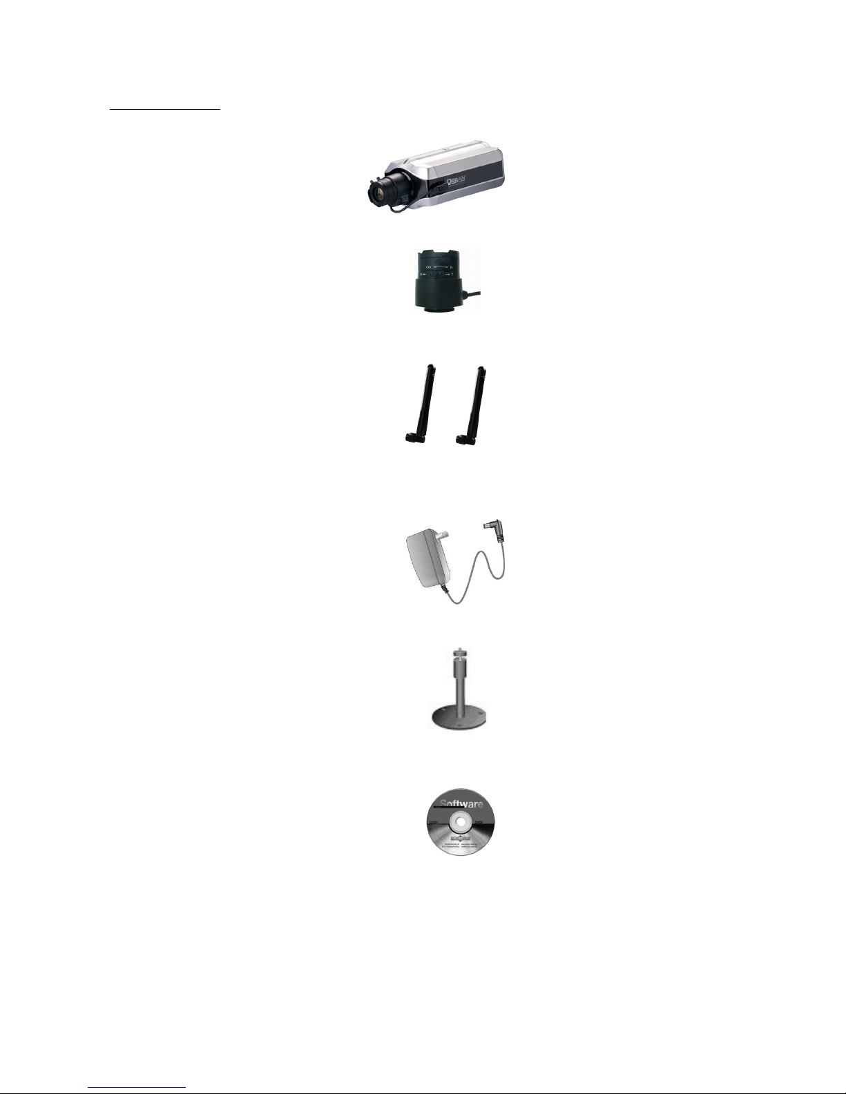
Scope of delivery
Network camera
Lens
Antennas (only TV7211,
TV7213, TV7215, TV7217)
Transformer
Camera mount
Software CD
Installation instructions (on CD)
7
Hardware installation
When the camera is switched on, it runs a self-test, and the Power/Activity LEDs flashes blue and red. If this self-test
completes successfully, the LED flashes blue and the Network camera is ready for you to enter an IP address. After
you enter an IP address, the blue LED flashes once every second. If the self-test is not successful, the red LED flashes
several times. For troubleshooting hints, see Appendix A.
The network camera will first detect Ethernet. If it does not connect to Ethernet, the network camera will try WLAN.
During the searching and connecting process to the wireless access point or station, the LED of the network camera
will keep red. Until the network camera is connected to the other wireless device, the LED wil become blue and
flash. Operating in either network mode, the blue LED will flash every second as heartbeat to indicate alive.
Installation in Ethernet
Make sure the Ethernet is firmly connected to a switch. After attaching the Ethernet cable please plug in the power
adapter. If the LED turns off the be steady blue after self test, you can go to software installation. If the Ethernet is
not available, the network camera will switch to wireless LAN mode.
Installation in Wireless LAN
If the Ethernet is not available while power on, the network camera will search for any access point with SSID
“default”. Once an access point is found, the LED will turn green to wait for installation. If the network camera
environment cannot meet the default settings, install the network camera in Ethernet to proceed with wireless LAN
configuration.
Make sure that all accessories and articles
listed above are present in the scope of
delivery. Depending on application, an
Ethernet cable may be required. This
Ethernet cable must meet the specifications
of UTP Category 5 (CAT 5) and must not
be longer than 100 meters.
To prevent the risk of electric
shock, first connect the socket of the
transformer to the security network
camera before inserting the
transformer into the mains socket.
Consult your dealer for the correct installation of peripheral devices.

8
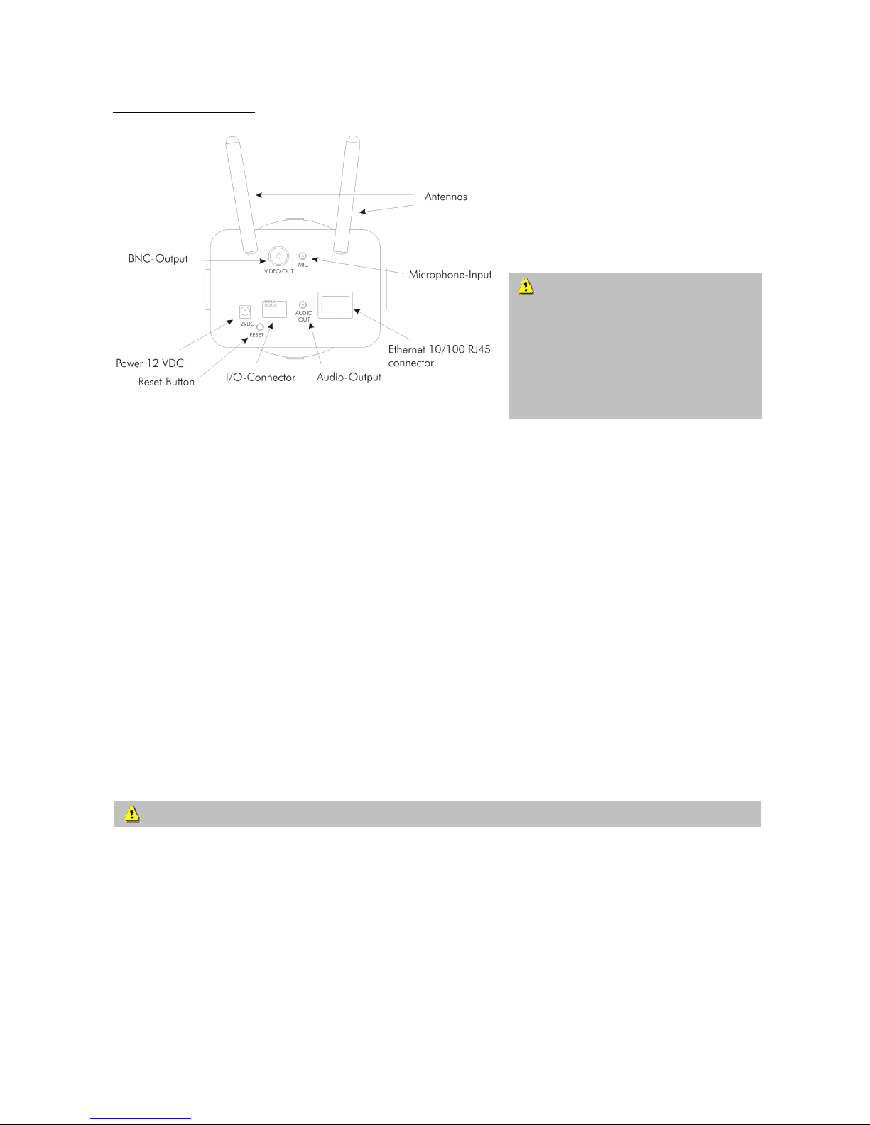
The Network camera is equipped via an I/O terminal block with a digital input and a relay for device control. At Pin
3 and Pin 4, an external digital input signal can be processed, whereby the voltage state is monitored in the start
phase at LOW. The output (Pin 1and Pin 2) can be used for switching external devices on and off.
1 RELAY OUTPUT (output status open)
2 RELAY OUTPUT (max. 1A, 24V DC)
3 DI+ INPUT (max. 50mA, 12V DC
4 DI- INPUT (output status of DI is low)
9
First access to Network camera
Setting the IP address
To set the IP address of the camera:
Use a network cable to connect the Network camera to your computer network.
(The simplest way is to connect the Network camera direct to your PC using a cross-link cable.)
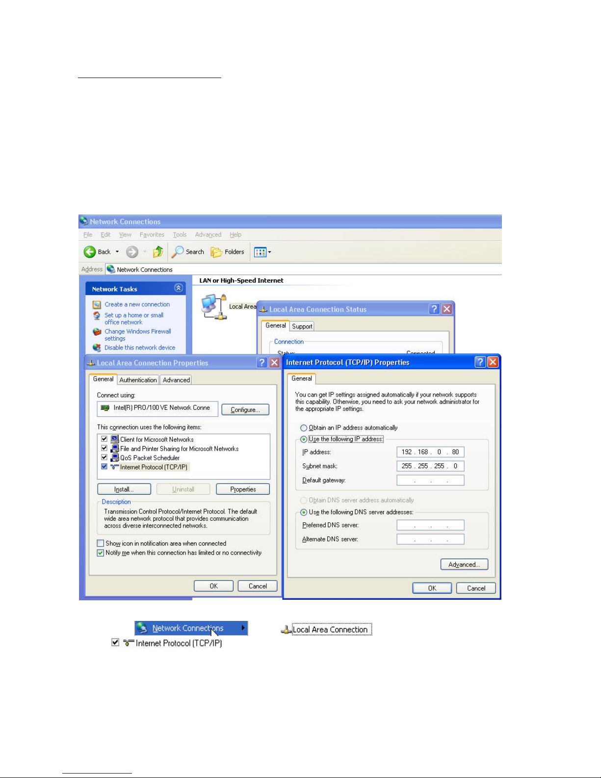
If your PC is not yet integrated into a network, you first have to configure it for the network application. Do this by
opening the Properties page for your network.
(This also applies if the camera is connected to the PC via a hub or switch.)
1. Click
, select and open the Properties page of the
.
2. Enter a fixed IP address and subnet mask
(e.g.: 192.168.0.80 and as subnet mask 255.255.255.0).
10
- The network connection of your PC is now configured.
3. Now start the Installation Wizard from the software CD supplied.
4. Follow the installation instructions of the Installation Wizard.
5. If installation is successful, start the program under Programs/Installation Wizard.
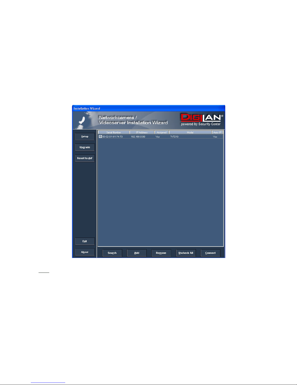
6. Following the program start, the Installation Wizard automatically searches for a connected network
camera.
7. If no camera is found in the first search, click “Search” for a new search.
Note:
The IP addresses shown in the “Current IP Address” field reflect those on the local network. They may be from the
DHCP server. If there is no DHCP server, the camera will try to find a free IP address (this takes from 15 seconds to
3 minutes, depending on the LAN status). The method of finding an IP address is seeking from 192.168.0.99, to
192.168.0.254. If any of the address inside this range is free, the network camera will be assigned to this IP
address, and its subnet mask would be 255.255.255.0. If none of the addresses is free, the network camera will try
the range from 192.168.0.2 to 192.168.0.98. After an IP address is assigned to the camera, the “Activity” status
LED blinks.
Note: If no camera is found via the manual search, change the network settings of your PC as described in the
instructions.
11
8. Select one of the camera models found.
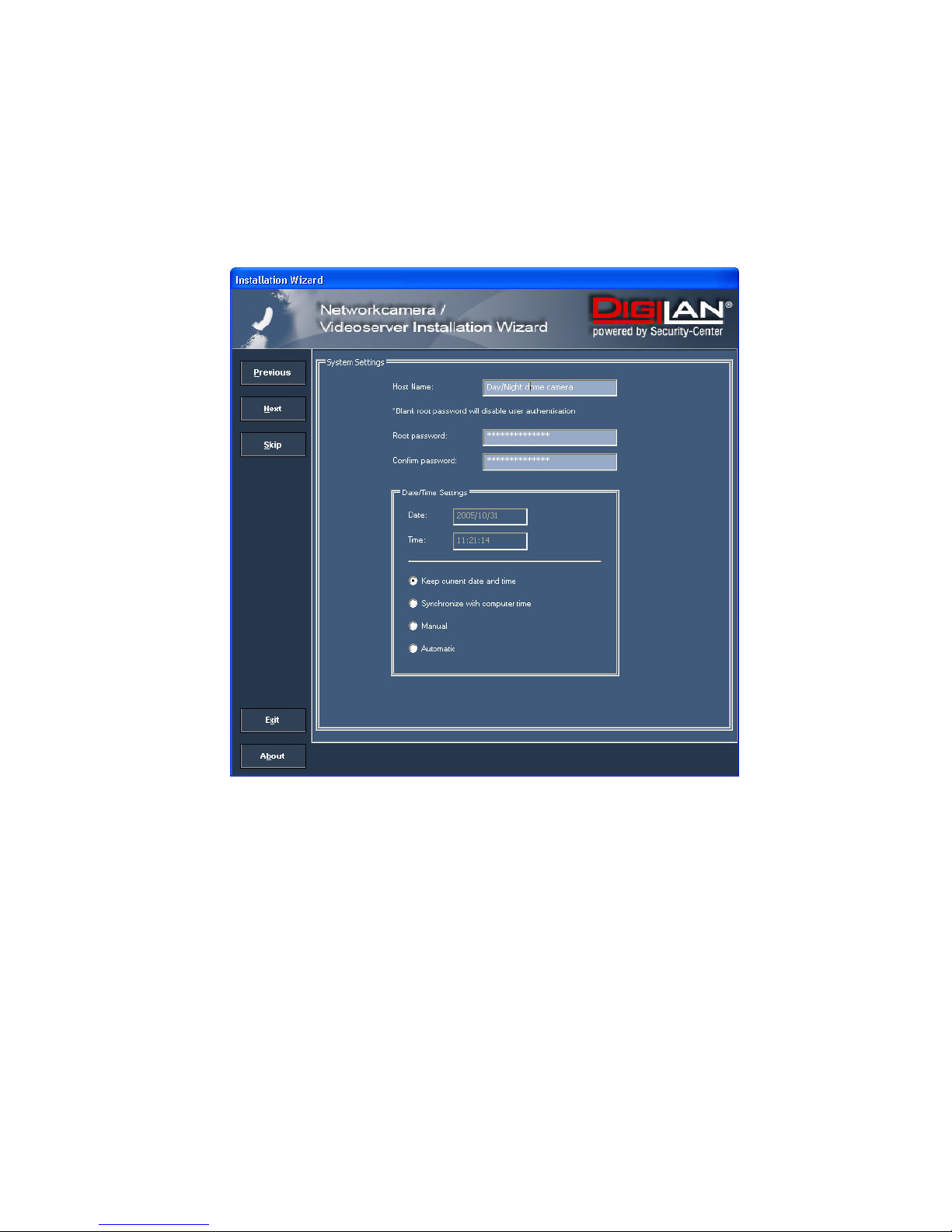
9. Click “Setup” to enter camera setup mode. If a password is required, use the device serial number
(no spaces, uppercase letters only). You can change the hostname, the administrator password and the
date/time settings of the camera. If you cannot access the settings, check the IP addresses of your
network adapter and your network camera. The IP addresses must be in the same subnet area. If
necessary, change the IP address of the network adapter (page 7).
12
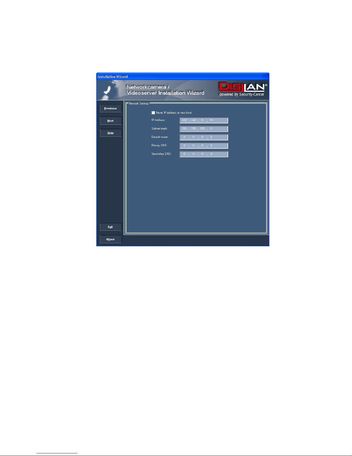
10. Now click “Next” to change the IP address of your network camera.
If you use a router in your network, enter this IP address (gateway) in the Default Router field.
11. If you disable “Reset IP address at next boot”, you do not have to reassign the IP address of this camera
following a power failure. Otherwise, you have to reassign the IP address after every camera restart.
12. Click “Next”.
13
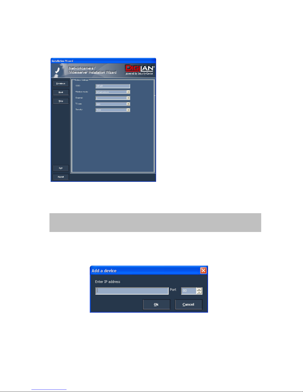
Now press the button “Skip” to skip the wireless LAN setup at this point. You will find more information under
“WLAN configuration”.
13. Follow the instructions on the screen to save or change your settings.
14. Click “Add” to add a network camera direct via the IP address or its domain name. You need this only if the
camera was not found by the automatic search.
15. Click “Remove” or “Uncheck all” to remove one or all network cameras from the menu.
16. Click “Connect” to set up a link to the selected network camera via the Internet Explorer.
The Installation Wizard is finished. Click “Previous” to change your settings. Click “Apply” to save your
input and transfer it to the selected device.
14
Access to the network camera via the Internet Explorer
Defining a password to prevent unauthorised access
For security reasons, the administrator should define a new password immediately. After the new administrator
password is stored, the Network camera asks for the user name and password every time it is accessed. The
administrator can define up to twenty (20) user accounts. Every user has access to the Network camera, but not to
the system configuration. Some system-critical functions are reserved for the administrator, such as system
configuration, user administration and upgrading software programs. The administrator’s user name is always
root and cannot be changed. Following a password change, the browser displays an authentication window and
asks for the new password. After changing the password, you cannot restore the original administrator
password. Your only option is to reset all default factory settings/parameters.
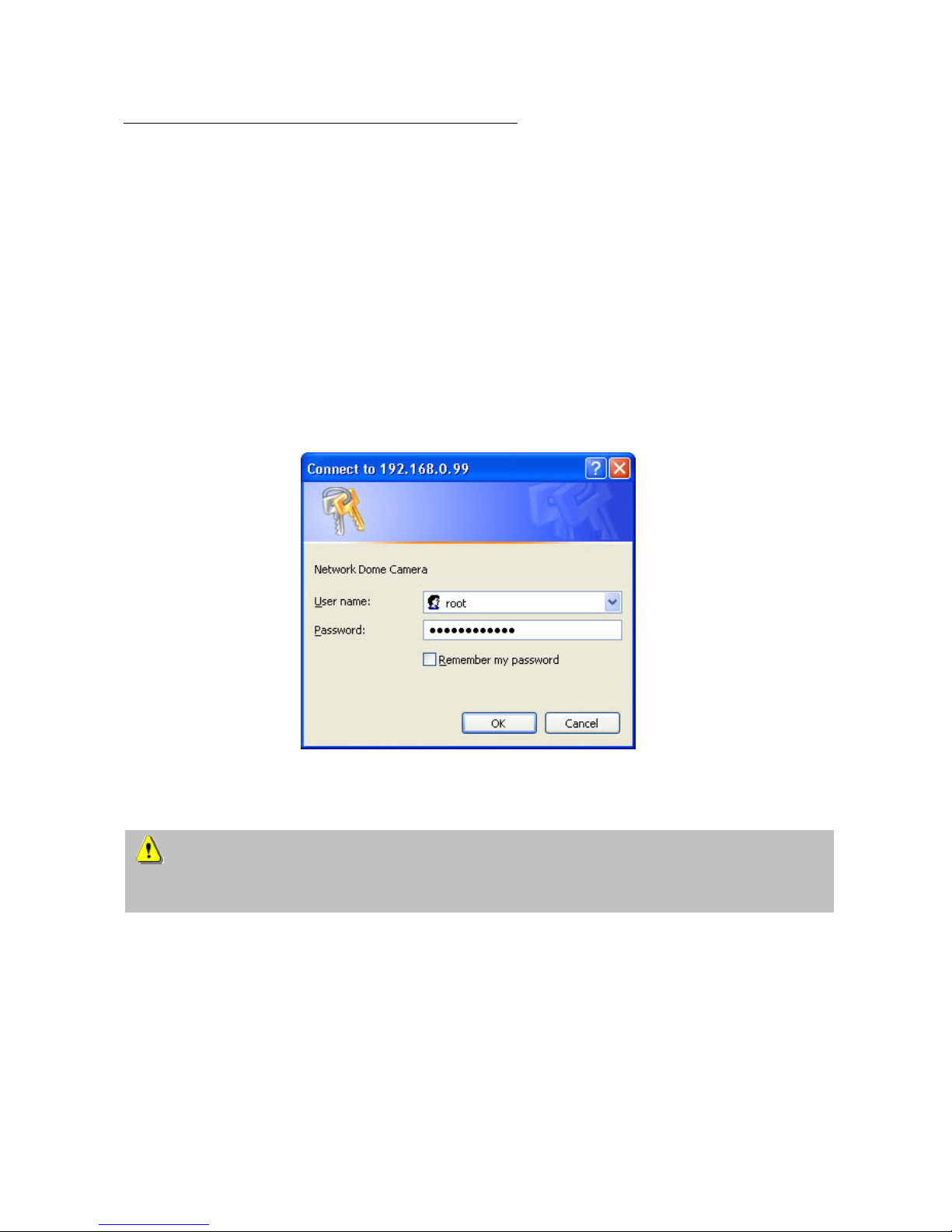
To enter the password:
Open the Internet Explorer and enter the IP address of the camera
(e.g.: <http://192.168.0.99>).
You are prompted for authentication:
Î You are now connected with the Network camera and can see a video stream.
Note: It may happen that your PC’s security settings prevent a video stream. You can change the security
settings to a lower level under “Tools/Internet Options/Security”. Make sure you enable Active X Control
Elements and Downloads.
15
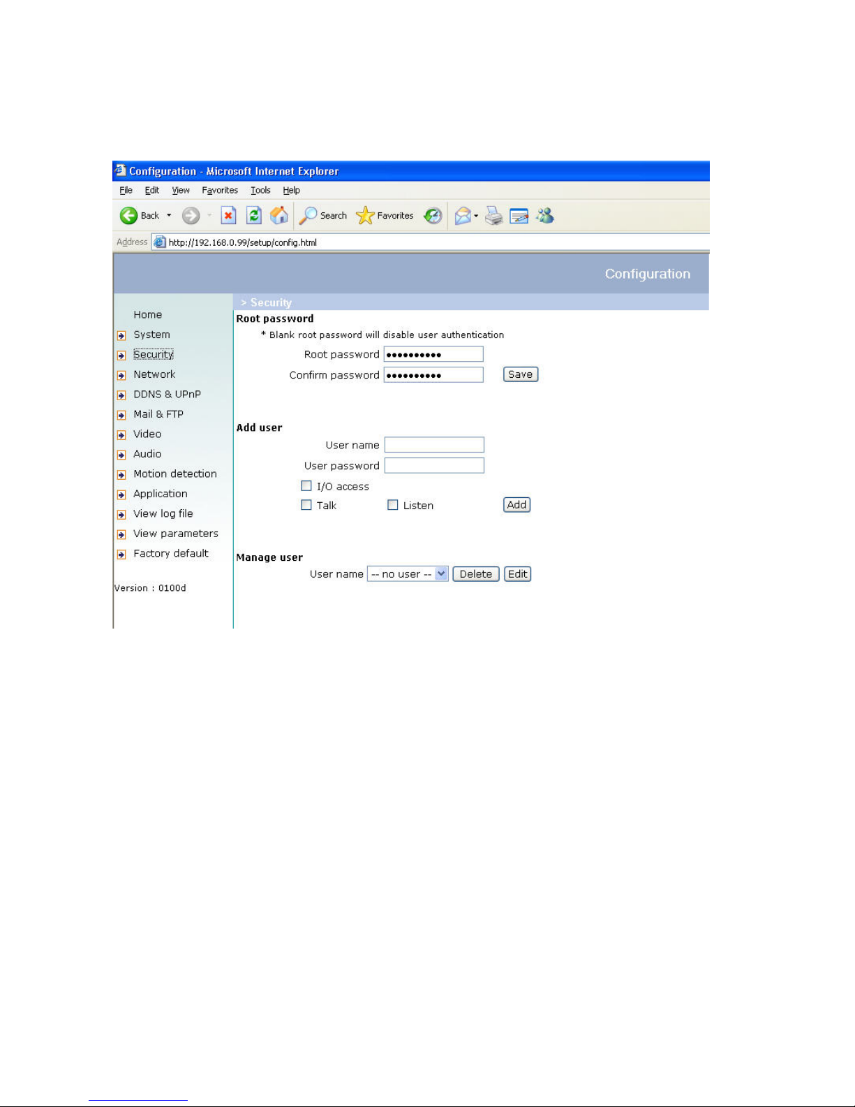
Changing the administrator password
Click “Configuration” and then “Security”.
Under “Root password”, enter the administrator password and confirm it under “Confirm password”.
Click “Save”.
The new administrator password is saved.
Click “HOME” in the column on the left to exit configuration.
16
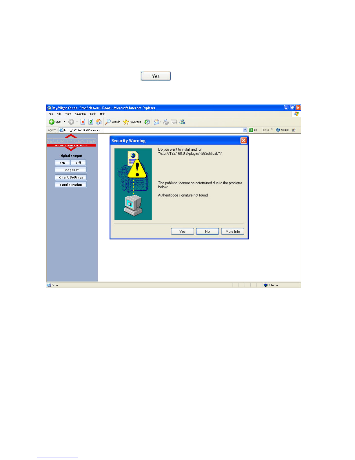
Installing the plug-in
When you first access the Network camera under Windows, the web browser may ask for the installation of a new
plug-in for the Network camera. This query depends on the Internet security settings of your PC. If the highest
security level is set, the PC will refuse any installation and any attempt at execution. This plug-in is used for video
display in the browser. To continue, click
. If the web browser prevents continuation of the installation,
open the Internet security settings and reduce the security level or consult the IT administrator or network
administrator.
17
Basic user functions
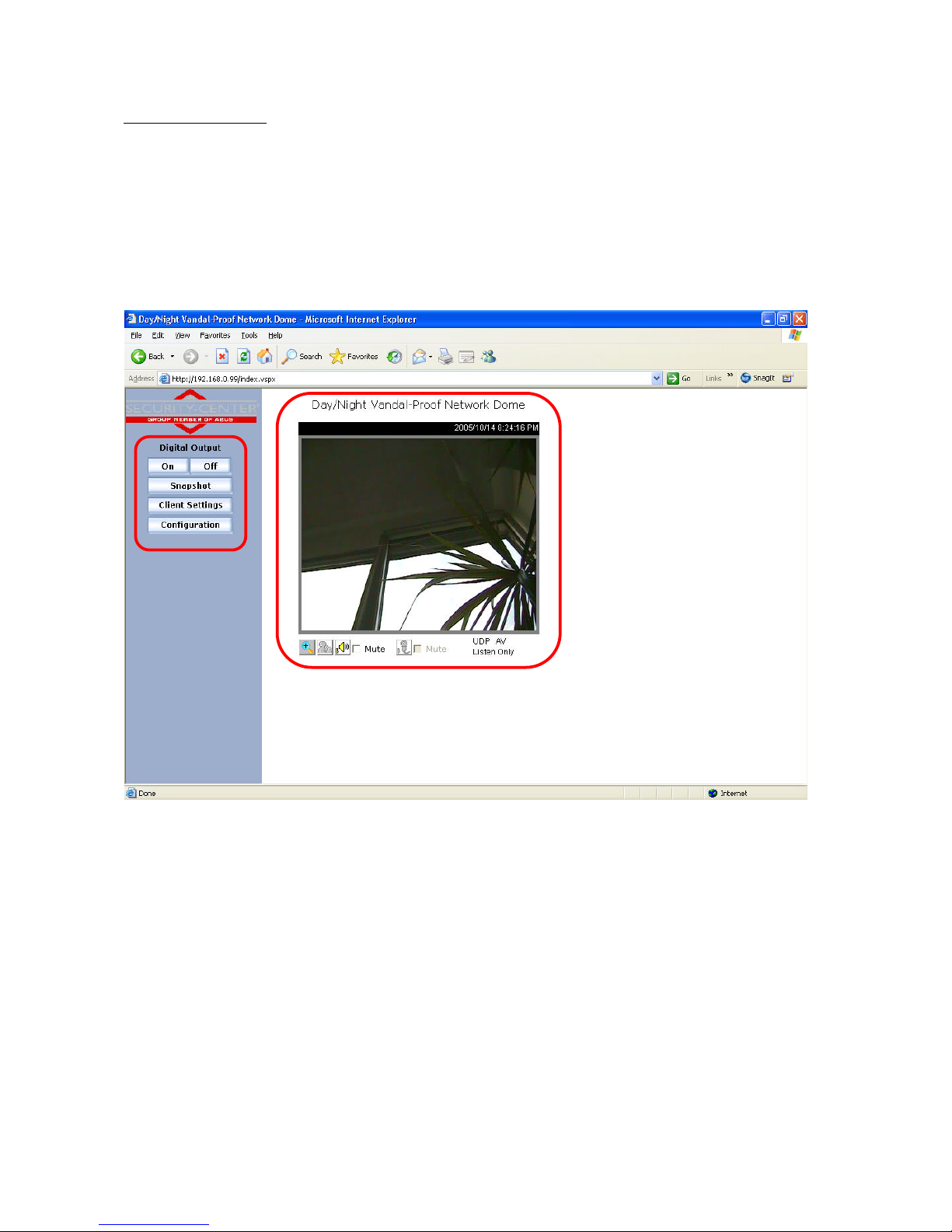
Main window and camera view
The view of the main page consists of two parts:
Configuration: The camera can be configured via this user interface.
Camera view: Camera video stream
Click the configuration link on the left of the picture to open the configuration page.
18
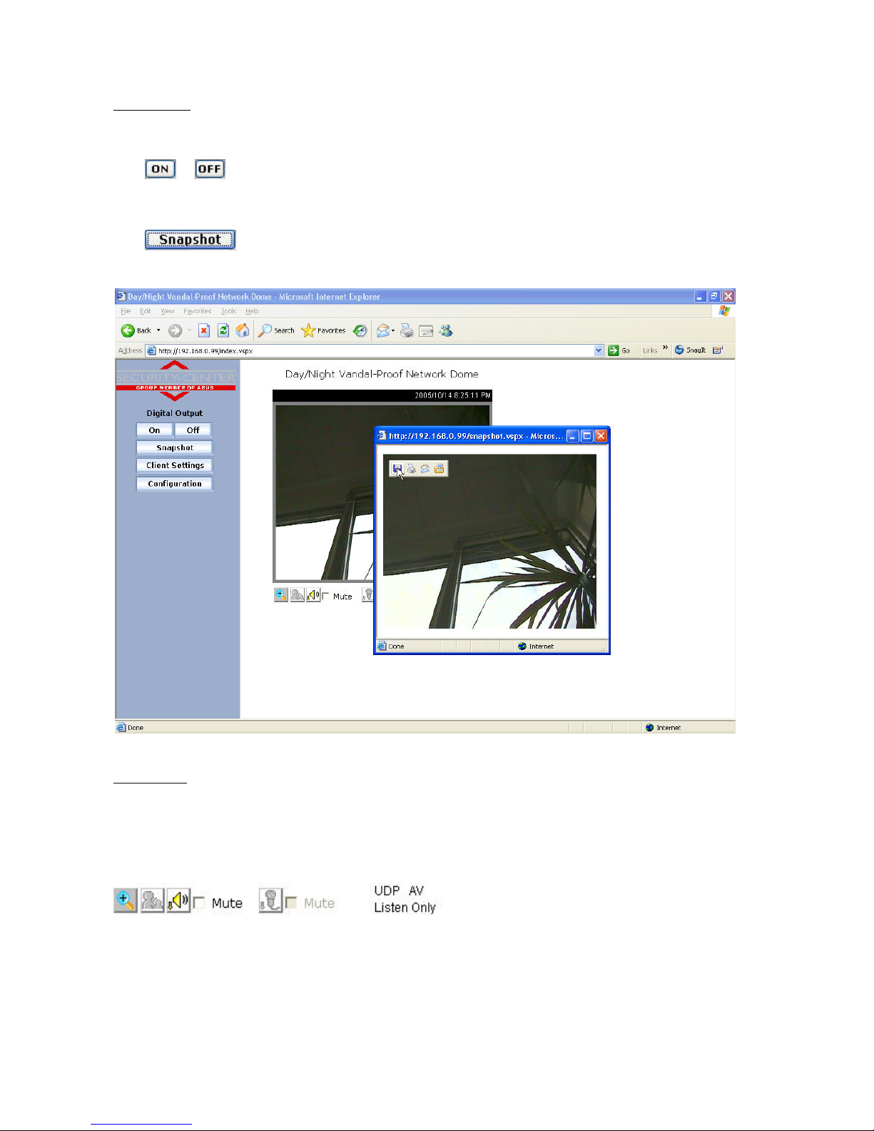
Configuration
Digital Output
Click
or to switch the relay output on/off.
Snapshot
Click
. The web browser displays a new window containing the snapshot. To save the snapshot,
either left-click it and then click the diskette icon or right-click it and select Save from the context menu.
Camera view
The information bar at the top of the camera view shows the assigned caption and the current date/time. The
information bar at the bottom of the camera view shows the current streaming mode and audio transmission mode.
You can push/toggle the talk button to talk to the remote server. The volume of speaker and microphone can also
be adjusted.
Zoom
Click the magnifying glass under camera view. The control field for digital zooming appears. Disable the Disable
Digital Zoom box and change the zoom factor with the slider.
19
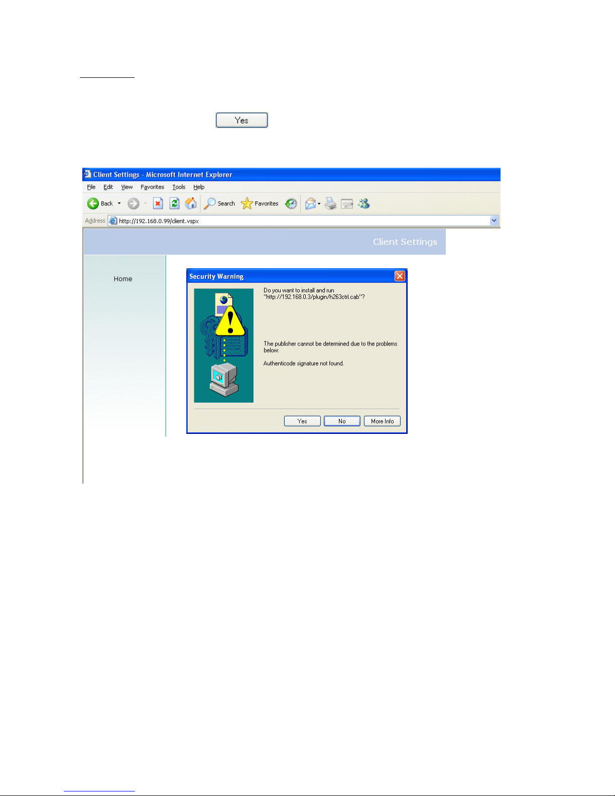
Client settings
When you first access the Connection Type page under Windows, the web browser asks for the installation of a new
plug-in. This plug-in was registered at certification and can be used to change parameters on the Client settings
page. To install the plug-in, click
. If the web browser prevents continuation of the installation, open
the Internet security settings and reduce the security level or consult the IT administrator or network administrator.
20
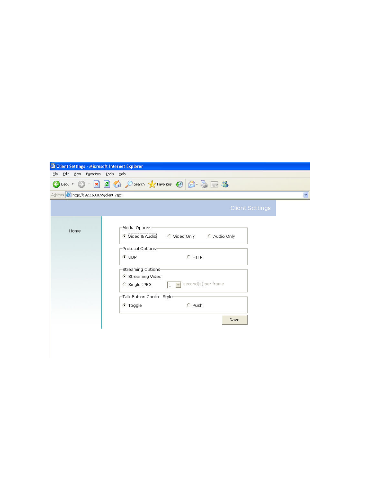
Two settings are available on the Client settings page. Under “Media Options”, you can disable the audio function.
Under “Protocol Options”, you can select a transmission protocol for data transfer between the client and the
server. Three protocol options are available for optimising the application: UDPand HTTP.
The UDP protocol gives you a larger number of realtime audio and video streams. However, some data packets
can be lost due to the large data volume in the network. Pictures can be unclear. The UDP protocol is
recommended if you have no special requirements.
Use the HTTP protocol if the network is protected by a firewall and only the HTTP port (80) is to be opened. In this
mode, no audio is transmitted.
The selection of the client is normally recommended in the following order: UDP – HTTP. When the Network
camera has been successfully connected, the “Protocol Options” box shows the selected protocol. The selected
protocol is registered in your PC and used for the next connection. After changing the network environment or if you
want to search again for the Network camera using the web browser, select the UDP protocol manually, save it and
then return to “HOME” to set up the connection again.
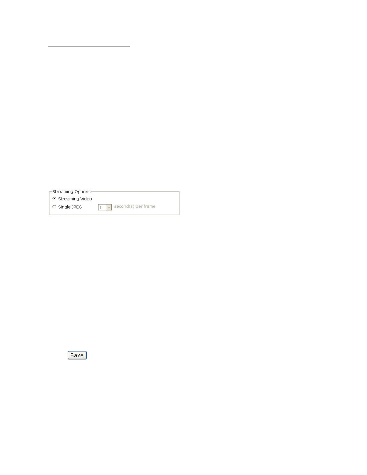
“Streaming Options” For users to select the video streaming types. Select “Streaming Video” option, the video
connection will keep alive to enable you to see smooth video, while “Single JPEG” option will let you see the video
in JPEG format by client periodic update the JPEG image from server according to the “Frame rate” settings.
“Talk Button Control Style” For the user to determine whether to “click once and talk” or “push to talk”.
<url> http://<Network Camera>/protocol.html
Network Camera is the original IP address or the hostname of the Network camera.
21
Administrator settings
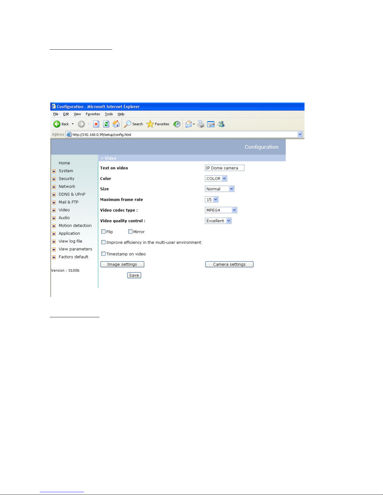
Configuration / video
Best performance is produced by the maximum frame rate with best video quality and minimum network bandwidth.
The six factors “Size”, “Maximum frame rate”, “Video codec type”, “Key frame interval”, “Fix bit rate” and “Fix
quality” on the video configuration page are correlative to allow for achieving the best performance that is possible.
For high frame rates
To obtain a good visual realtime effect (more than 20 frames/s), the network bandwidth must be sufficiently large. If
the network bandwidth is higher than 1 Mbps, the value for the “Fix bit rate” must be set to 1000Kbps or 1200Kbps
and the “Fix quality” to the highest quality. In the PAL system, the maximum frame rate is 25, and in the NTSC
system, 30 frames per second. If your network bandwidth is more than 384Kbps, you can fix the bit rate according
to your bandwidth and the maximum frame rate to 25 or 30 fps (frames per second). If the pictures in your
environment are changed drastically, you can reduce the maximum frame rate to 20 frames per second to set the
data transmission rate lower. This gives you a better video quality, and the human eye cannot distinguish between
20, 25 and 30 frames per second. If the network bandwidth is less than 384 Kbps, adjust the “Fix bit rate”
according to the bandwidth and try to get the best performance by fine-tuning the “Maximum frame rate”. In a
“slow” network, a high frame rate results in unclear, distorted images. Another way to improve quality is to select
“Half” in the “Size” option, or “Half x 2” for a larger view of the pictures. Video quality also depends on the number
of users in the network. Performance can also be affected by a bad connection and by a restriction of the network
burst.
In multi-user environment, the user who has poor network performance will receive only the key frame in MPEG4
format. Try to reduce the key frame interval can improve the frame rate for poor network performance, but the
penalty is the increasing of network traffic. If the server is running on the Internet, select “Improve efficiency in the
multi-user environment” will improve the efficiency in the multi-user environment.
22
For higher-quality pictures
For best video quality, set “Fix quality” to “Detailled” or “Excellent” and the “Maximum frame rate” so that it
corresponds to the bandwidth of your network. If your network is slow and you get “broken” images, go to the HTTP
protocol under “Protocol Options” and select a more suitable transmission mode. Pictures can also be affected by
a time delay due to a slower connection. The more users in the network, the greater this time delay.
For high frame rates with high-quality pictures
If you have a broadband network, set “Fix bit rate” to “512Kbps” or higher and leave “Fix bit rate” unchanged. You
can also set the bandwidth according to the actual network speed or the frame rate. Start with 25 frames per
second and reduce this setting until you get the best performance. However, do not reduce it to less than 15 frames
per second. If the picture quality is not improved, select a lower setting for “Fix bit rate”.
Select Motion-JPEG (MJPEG) for video codec type
The network camera is a camera with dual video codec, MPEG4 and MJEPG. If MJEPG is selected the camera will
transmit video data in JPEG format. Therefore, it requires higher bandwidth to view smooth video. General
speaking, each normal sized JPEG image would be 3k~12k bytes, depending on the selected video quality and
contents. Together with the frame rate selected, the administrator can control the bandwidth of each connection.
Protecting the Network camera with a password
Root password
The DIGI-LAN Network camera is delivered without password. In this case all users have access to the Network
camera, including its configuration, as long as they know the IP address. If other users are to have access to the
Network camera, you should therefore assign a password to the camera. To activate protection, enter a new
password. The administrator is identified with this password.
Opening accounts for new users
Under “Configuration”, select “Security”. Now go to the Add user section.
Add an account with user name and password for a second user. You can define up to twenty accounts for other
users of the Network camera. The camera checks only the access permission of the corresponding user name and
password. This means that two or more users can use the same account at different levels. An option for access to
the relay “I/O access” is available for every account.
23
More flexible options for the viewer
Allow “demo” account to view:
If you want to have a guest account for viewers only, you just need to add a user without password and disable all
privileges. Share the account to you friends.
Format of a multimedia website
Demo on two or more pages – medium-scale service
The Network camera allows up to ten online visitors simultaneously. Following installation, you focus the Network
camera on a picture and inform the visitors of the web browser address. Caution: Keep your guest list on the
security configuration page to prevent visits by unwanted visitors.
Product demo for e-Business – large-scale service
If the number of visitors exceeds the limit, the Network camera enables the pictures to be viewed as snapshots in
JPEG mode. These pictures are displayed as stills and updated automatically. This requires a script function that is
supported by the web browser.
1. On the homepage, click “Client settings”.
2. Select “Single JPEG” in “Streaming Options”,
3. Set the snapshot interval for automatic updating of the still picture. The greater the snapshot interval, the better
the snapshot mode works for more viewers.
If you want to extend the function for a larger number of visitors, the host server must be capable of handling large
traffic volumes in the network in order to be able to update the pictures from the Network camera.
If the website has an FTP service
Define the Network camera as an FTP client. Access to the Network camera depends on the number of visitors; the
picture quality remains constant.
1. On the homepage, click “Configuration”.
2. In the left column, click “Mail & FTP”.
3. Enter the FTP-specific settings, including the server, user name, and password, plus the path for uploading, if
required by the website.
4. Click
; the system is restarted.
24
5. In the left column, click “Application”.
6. To upload the pictures, select the weekday and the daily schedule.
7. Select “Sequential operation” and set the interval.
8. Unselect the FTP without the date/time suffix as transfer method and click
9. The image file uploaded to the web is named video.jpg. Make sure that the file is uploaded to the right folder.
10. Prepare a homepage with the integrated picture reference for the image file previously uploaded via FTP.

25
If no FTP service is available in the web
An automatically updated homepage can be used for occasional retrieval of the latest pictures from the Network
camera. You get the best performance by using a free website provider, since the FTP service can be restricted.
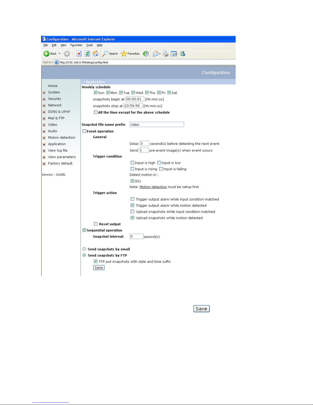
Alarm inputs/outputs
Configuration / application
The administrator can combine options on the application page to permit the running of a large number of security
applications. Two inputs, e.g., for motion detection, are available. There are also two outputs that react to such
events, including uploading of snapshots via the Internet and switching other connected actors. You can use either
FTP or e-mail to upload snapshots. Both e-mail and FTP use the network settings on the homepage. For
specifications of a detailed configuration, see the “System configuration” section.
<html>
<head>
<title>Example – auto refresh page</title>
</head>
<body>
<p align=left>
<font size="7" face=”Comic Sans MS" color="#FF0000">MiniAVServer
Demo</font>
</p>
<p align left>
<!—Begin of scripts to auto refresh the image. Change the IP address in the
image URL and refreshrate if necessary.-->
<script language=javascript>
var RefreshRate=1;// Refresh Rate in Seconds
var SourcePic="http://62.153.88.101/cgi-bin/video.jpg";
var WidthPic=352;
var HeightPic=288;
function refresh(){
document.images["Picture"].src=SourcePic+"?"+new Date();
setTimeout('refresh()', RefreshRate*1000);}
document.write('<img src="'+SourcePic+'" height="'+HeightPic+'"
width="'+WidthPic+'" name="Picture">');
if(document.images) window.onload=refresh;
</script>
<!—-End of scripts to auto refresh the image.-->
</p>
</body>
</html>
26
Time-controlled surveillance
1. On the homepage, click “Configuration”.
2. In the left column, click “Application”.
3. Click the boxes next to the weekdays you require and define the time period under “Snapshots begin at” and
“Snapshots stop at” for daily supervision of the trigger conditions.
4. Enable “Event operation”. The trigger condition can be set to detect series of motions or the status of the
connected device.
5. The delay before detecting the next event is used to prevent continuous error display following the original event.
6. The delay for recording a snapshot after the event is used for recording the direction of moving objects.
27
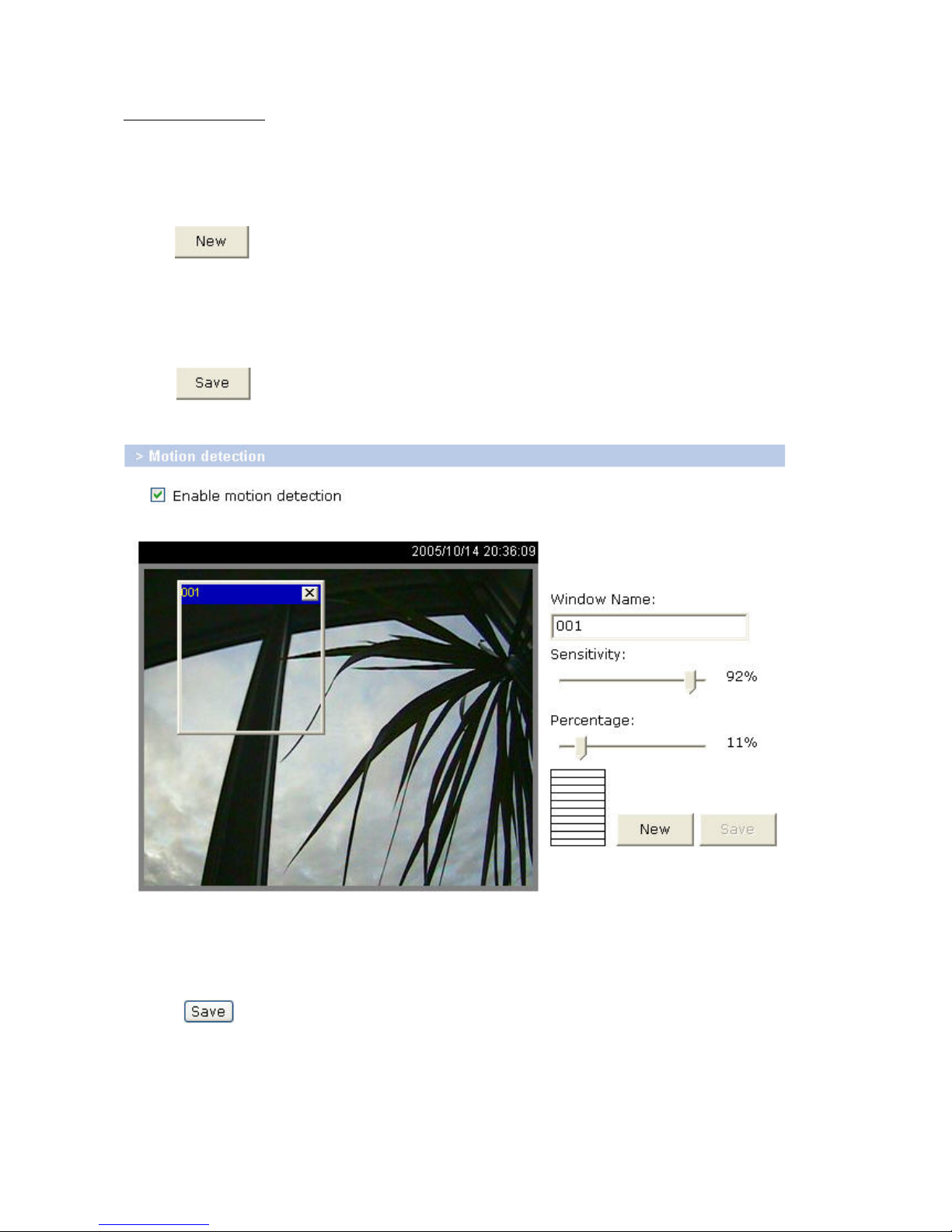
Integrated video sensor
If no external sensor is available, the administrator can use the integrated motion sensor to monitor movement and
send snapshots by e-mail for inspection.
1. In the left column, click “Motion detection”.
2. Enable “Enable Motion detection”.
3. Click
to keep a new window ready for supervising the video.
4. Enter a new name to identify the new window.
5. Click a corner of the window, keep the mouse button pressed, and adjust the size of the window for motion
detection or move the window.
6. You can fine-tune the camera with “Sensitivity” and “Percentage”. The higher the “Sensitivity”, the smaller the
changes that can be detected in the picture sequence. The lower the “Percentage”, the smaller the objects that can
be differentiated in a picture.
7. Click
to activate the bar graph (activity). Green means that the motion sequence is lower than the
level set by the administrator, and red means that the motion sensor has been triggered.
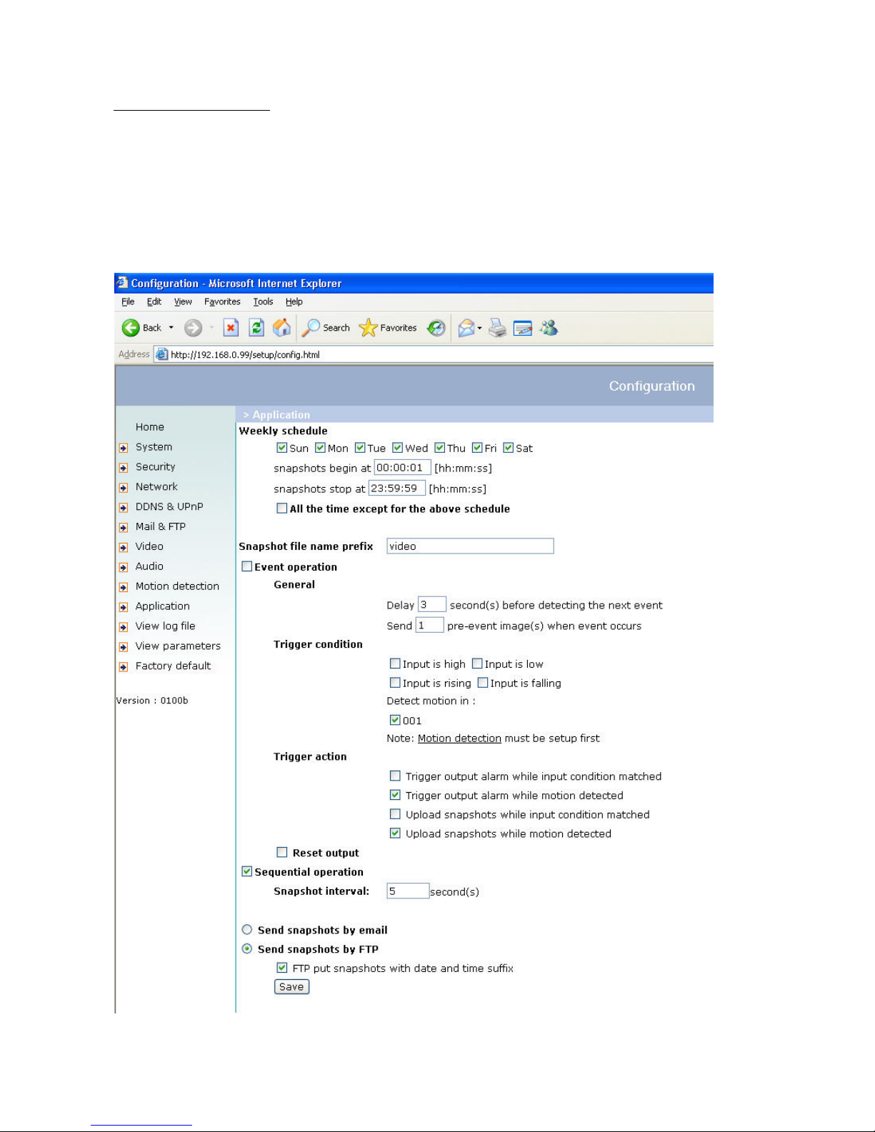
8. In the left column, click “Application”.
9. Under Event operation/Trigger condition/Detect motion in, select the window name.
10. Enable “Upload snapshots while motion detected” to transfer the snapshots by e-mail.
11. Enable “Send snapshots by email”.
12. Click
to activate the settings (activity).

28
Updating the software version
You can download the latest software from the website. A user-friendly update wizard (installation wizard) is
provided for updating the Network camera software. Only the administrator can start the update function. To
update the system:
1. Download the firmware file with the name TV721X_english.pkg from the corresponding products folder.
2. Start the update wizard and follow the instructions. For details, see the instructions of the update wizard.
3. The complete procedure finishes in a few minutes, and the system is automatically rebooted.
If there is a power failure during the write process of the flash memory, the program in the
memory of the security network camera may be irreparably damaged. If the security network camera
cannot be correctly restarted following the update, consult your dealer’s technical support.
29
System configuration
Only the administrator has access to system configuration. The following sections explain each element in the left
column. Specific tasks on the Options page are printed bold. The administrator can enter the URL under the picture
to jump direct to the pictures page of the configuration. For setting specific options via the URL, see Appendix C.
“url” http://”Network Camera”/setup/config.html
“Network Camera” is the domain name or original IP address of the security network camera.
“url” http://”Network Camera”/setup/system.vspx
“Network Camera” is the domain name or original IP address of the security network camera.
30
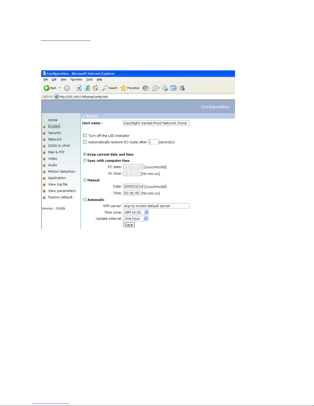
System
„Host name“ The text represents the title of the homepage.
„Turn off the LED indicator“ Select this option to switch of the LED on the rear of the camera. This prevents other
persons knowing that the camera is in use.
„Keep current date and time“ Click this option to keep the current date and time of the security network camera. An
internal realtime clock stores the date and time after the system is switched off.
„Sync with computer time“ Synchronises the date and time of the security network camera with the local computer.
The read-only date and time of the PC are displayed following updating.
„Manual“ Sets the date and time according to the administrator’s input. Note the date/time format when entering in
the respective fields.
„Automatic“ Synchronises the date and time with the NTP server via the Internet every time the security network
camera is switched on. This is not possible if the respective time server cannot be reached.
„NTP server“ Assigns the IP address or the domain name of the time server. If you leave this text box empty, the
security network camera is connected to the default time servers.
„Time zone“ Sets the time according to the time server for local settings.
“Update interval” Select hourly, daily, weekly or monthly update with the time on the NTP server.
Don’t forget to click
to make your settings take effect; otherwise, the time is not synchronised.
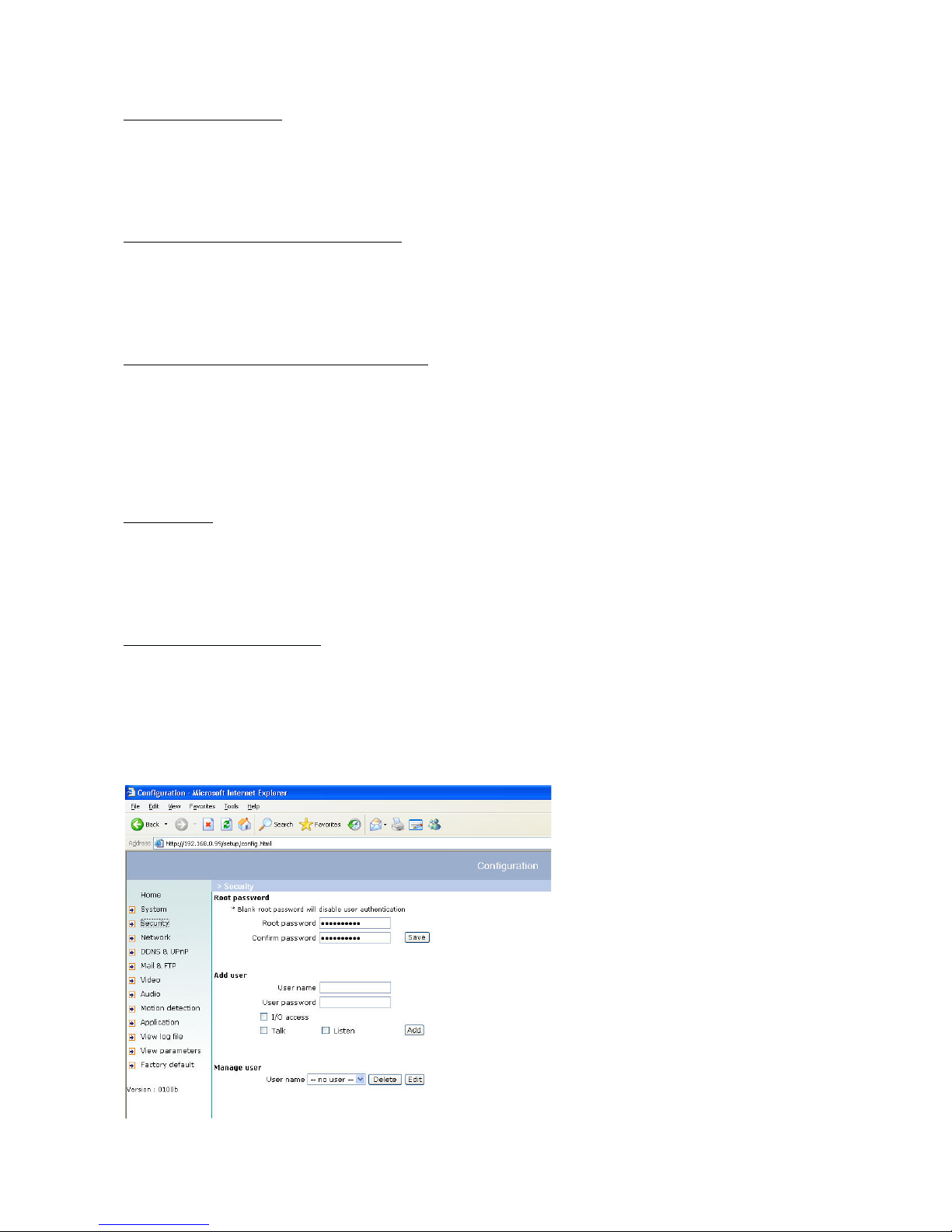
Security
„Root password“ For changing the administrator password by entering a new password. For security reasons, the
passwords entered are represented by asterisks. After
is clicked, the web browser prompts the administrator
to enter the new password for accessing the network camera.
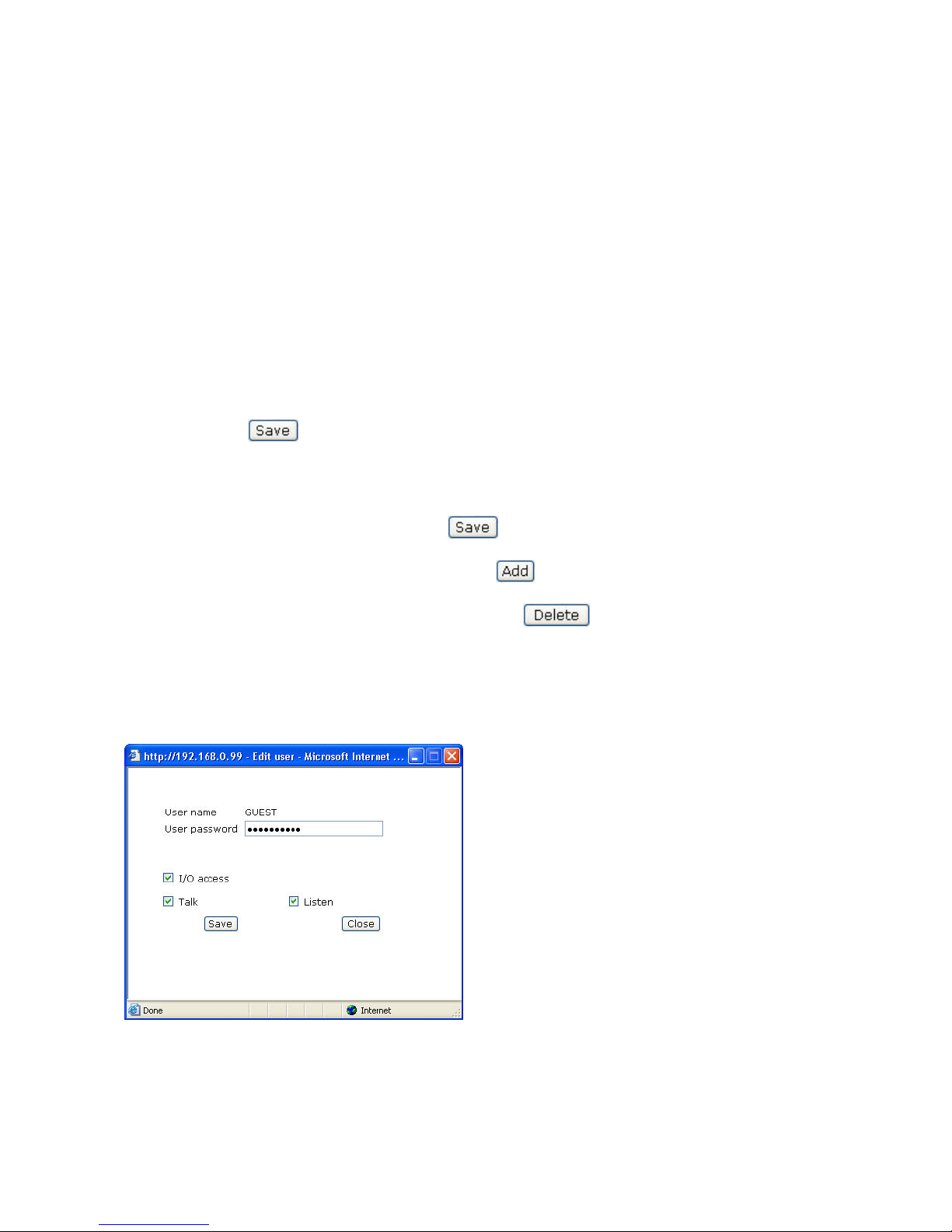
„Add user“ Enter the new user name and password and click . The new user is displayed on the list of user
names. Up to twenty user accounts can be defined. You can assign “I/O access”, ”Talk” and “Listen” to every user.
„Delete user“ Open the list of user names, select a user and click
to delete this user.
“I/O access” Allows user to control the DO (Relay output) and get status of the DI (Digital input).
“Talk” Allows user to talk to the server
“Listen” Allows user to listen from the server.
“Delete user” Pull down the user list to find the user’s name and press “Delete” to complete.
“Edit user” Pull down the user list to find the user’s name and press “Edit” to edit the user’s password and privileges.
“url” http://”Network Camera”/setup/edituser.vspx
“Network Camera” is the domain name or original IP address of the security network camera.
“url” http://”Network Camera”/setup/security.vspx
“Network Camera” is the domain name or original IP address of the security network camera.
 Loading...