

Page 1
Network camera
Installation instructions
TV7210
TV7217
Page 2

2
Preface
Dear Customer,
Thank you for purchasing this Network camera of the DIGI-LAN series from Security Center. You made the right
decision in choosing this state-of-the-art technology,
which complies with the current standards of domestic and European regulations. The CE has been proven and all
related certifications are available from the manufacturer upon request.
To maintain this status and to guarantee safe operation, it is your obligation to observe these operating instructions!
In the event of questions, please contact your local specialist dealer.
This Network camera is used for object surveillance. The recorded video signals are transmitted to a computer
digitally via the connected network. The computer software permits simultaneous recording of up to 16 connected
video signals. Data storage is subject to local national data-protection guidelines. Via the Internet Explorer, you
have worldwide access to installed cameras (password-protected).
Precautions
The Network camera and connected components must be kept free of moisture (cellars and similar surroundings
are to be strictly avoided). Use of this product for other than the described purpose may lead to damage of the
product. Other hazards such as short-circuiting, fire, electric shock, etc., are also possible. The equipment is
designed for operation using a Class 2 12V DC transformer. No part of the product may be changed or modified
in any way. Connection to the public power network is subject to country-specific regulations. Please be aware of
applicable regulations in advance.
To avoid fire and injury, please observe the
following:
Securely fasten the device at a dry location in the
building.
Ensure sufficient air circulation.
Do not expose the device to temperatures less than
0°C or more than 35°C.
The device is designed for indoor use only.
Humidity must not exceed 85% (non-condensed).
Ensure that the voltage is disconnected when
performing work on the device.
Please observe the following regulations to ensure
trouble-free operation of your device.
The Network camera is supplied by a 12V DC
transformer.
The transformer should be connected to the 230V
AC building mains by means of a separate,
electrically protected line.
Connection work to the building mains is subject
to country-specific regulations.
General:
Improper or careless installation work may lead to faults and poor image quality. Therefore please read the
instructions very carefully and follow the installation instructions for lines and components precisely.
The manufacturer reserves the right to make technical modifications at any time.
Page 3

3
Before using this product
The use of surveillance equipment may be forbidden by law in some countries. This Network camera is not only
high-quality web camera but can also be used as part of a flexible surveillance system. Before using this equipment,
make sure that all your surveillance activities are completely legal.
Before installation, check the product for completeness (page 5: Scope of delivery). Read the installation instructions
before installing the Network camera. Read the “Installation” chapter carefully and follow the instructions contained
in it to avoid damage caused by faulty assembly or incorrect installation. This will ensure that the equipment goes
into operation correctly for the intended purpose.
Appendixes A and B (Troubleshooting, FAQ) contain possible solutions to problems occurring during installation
and configuration.
The installation instructions describe different usage scenarios of the Network camera. The chapter “URL
Commands of the Network camera” is intended to help professional users design their own homepage or integrate
the camera with web servers.
Sections marked with contain special hints and advice for the user. Ignoring this advice can result
in damage to the equipment or injury.
Page 4

4
Contents
Preface ........................................................................................................................................................2
Precautions ..................................................................................................................................................2
General: .............................................................................................................................................2
Before using this product ............................................................................................................................... 3
Contents ...................................................................................................................................................... 4
Scope of delivery ..........................................................................................................................................6
Hardware installation .................................................................................................................................... 7
Installation in Ethernet.......................................................................................................................7
Installation in Wireless LAN............................................................................................................... 7
First access to Network camera......................................................................................................................9
Setting the IP address ........................................................................................................................ 9
Note: ................................................................................................................................................ 10
Access to the network camera via the Internet Explorer...................................................................................14
Defining a password to prevent unauthorised access ............................................................................. 14
Changing the administrator password ............................................................................................15
Installing the plug-in .......................................................................................................................16
Basic user functions ....................................................................................................................................17
Main window and camera view.......................................................................................................17
Configuration ....................................................................................................................................18
Camera view .....................................................................................................................................18
Client settings ....................................................................................................................................19
Administrator settings ..................................................................................................................................21
Configuration / video ...................................................................................................................... 21
Protecting the Network camera with a password ............................................................................22
Root password ......................................................................................................................22
Opening accounts for new users.............................................................................................22
More flexible options for the viewer ......................................................................................... 23
Format of a multimedia website......................................................................................................23
Demo on two or more pages – medium-scale service................................................................23
Product demo for e-Business – large-scale service.....................................................................23
If the website has an FTP service .............................................................................................23
If no FTP service is available in the web ...................................................................................25
Alarm inputs/outputs ..........................................................................................................................25
Time-controlled surveillance................................................................................................................26
Integrated video sensor....................................................................................................................... 27
Updating the software version .............................................................................................................28
System configuration...................................................................................................................................29
System .............................................................................................................................................30
Security............................................................................................................................................30
Network........................................................................................................................................... 31
WLAN configuration ........................................................................................................................ 32
DDNS and UPnP settings.................................................................................................................34
Mail & FTP........................................................................................................................................35
Video ...............................................................................................................................................37
Picture settings ......................................................................................................................38
Camera settings ....................................................................................................................38
Day/Night function (only TV7216 and TV7217) .......................................................................38
Audio...............................................................................................................................................39
Motion sensor..................................................................................................................................40
Application ......................................................................................................................................41
Viewing System log..........................................................................................................................42
Viewing System Parameters.............................................................................................................42
Factory default................................................................................................................................. 42
Page 5

5
Appendix ...................................................................................................................................................43
A. Troubleshooting ..........................................................................................................................43
B. Frequently asked questions (FAQ)...............................................................................................44
C. URL commands of the security network camera .........................................................................46
D. Technical specifications............................................................................................................... 61
Page 6
6
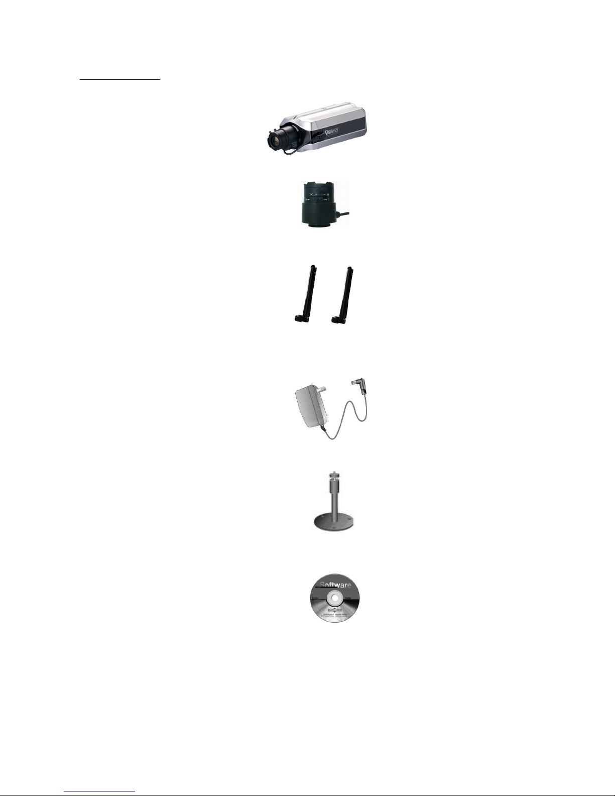
Scope of delivery
Network camera
Lens
Antennas (only TV7211,
TV7213, TV7215, TV7217)
Transformer
Camera mount
Software CD
Installation instructions (on CD)
Page 7
7
Hardware installation
When the camera is switched on, it runs a self-test, and the Power/Activity LEDs flashes blue and red. If this self-test
completes successfully, the LED flashes blue and the Network camera is ready for you to enter an IP address. After
you enter an IP address, the blue LED flashes once every second. If the self-test is not successful, the red LED flashes
several times. For troubleshooting hints, see Appendix A.
The network camera will first detect Ethernet. If it does not connect to Ethernet, the network camera will try WLAN.
During the searching and connecting process to the wireless access point or station, the LED of the network camera
will keep red. Until the network camera is connected to the other wireless device, the LED wil become blue and
flash. Operating in either network mode, the blue LED will flash every second as heartbeat to indicate alive.
Installation in Ethernet
Make sure the Ethernet is firmly connected to a switch. After attaching the Ethernet cable please plug in the power
adapter. If the LED turns off the be steady blue after self test, you can go to software installation. If the Ethernet is
not available, the network camera will switch to wireless LAN mode.
Installation in Wireless LAN
If the Ethernet is not available while power on, the network camera will search for any access point with SSID
“default”. Once an access point is found, the LED will turn green to wait for installation. If the network camera
environment cannot meet the default settings, install the network camera in Ethernet to proceed with wireless LAN
configuration.
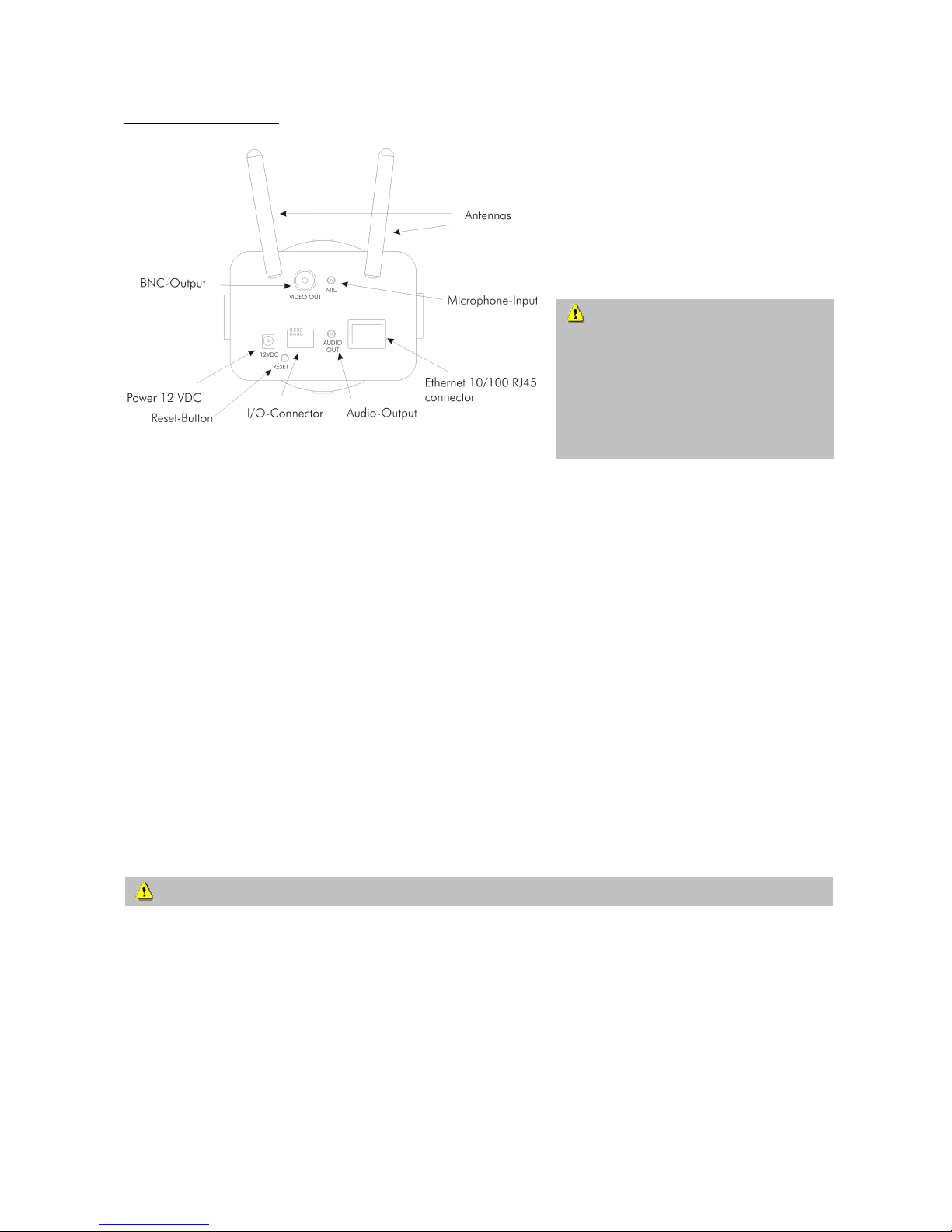
Make sure that all accessories and articles
listed above are present in the scope of
delivery. Depending on application, an
Ethernet cable may be required. This
Ethernet cable must meet the specifications
of UTP Category 5 (CAT 5) and must not
be longer than 100 meters.
To prevent the risk of electric
shock, first connect the socket of the
transformer to the security network
camera before inserting the
transformer into the mains socket.
Consult your dealer for the correct installation of peripheral devices.
Page 8

8
The Network camera is equipped via an I/O terminal block with a digital input and a relay for device control. At Pin
3 and Pin 4, an external digital input signal can be processed, whereby the voltage state is monitored in the start
phase at LOW. The output (Pin 1and Pin 2) can be used for switching external devices on and off.
1 RELAY OUTPUT (output status open)
2 RELAY OUTPUT (max. 1A, 24V DC)
3 DI+ INPUT (max. 50mA, 12V DC
4 DI- INPUT (output status of DI is low)
Page 9
9
First access to Network camera
Setting the IP address
To set the IP address of the camera:
Use a network cable to connect the Network camera to your computer network.
(The simplest way is to connect the Network camera direct to your PC using a cross-link cable.)
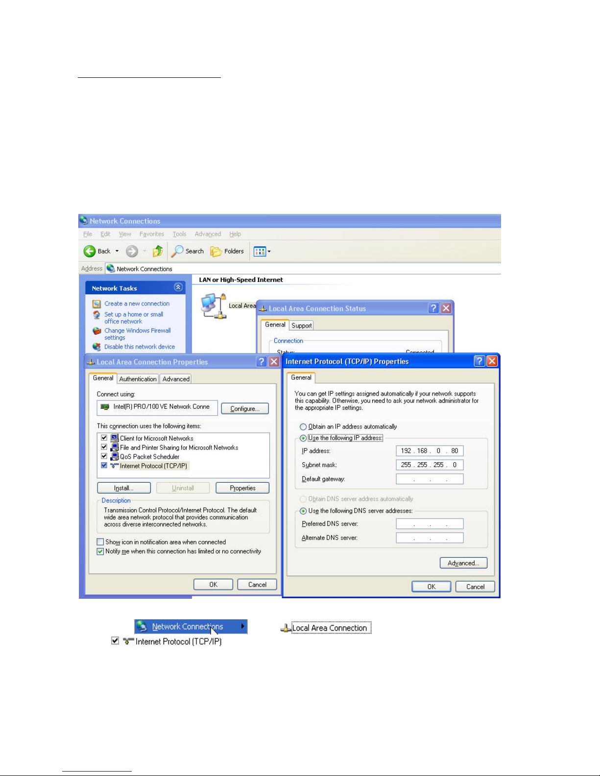
If your PC is not yet integrated into a network, you first have to configure it for the network application. Do this by
opening the Properties page for your network.
(This also applies if the camera is connected to the PC via a hub or switch.)
1. Click
, select and open the Properties page of the
.
2. Enter a fixed IP address and subnet mask
(e.g.: 192.168.0.80 and as subnet mask 255.255.255.0).
Page 10
10
- The network connection of your PC is now configured.
3. Now start the Installation Wizard from the software CD supplied.
4. Follow the installation instructions of the Installation Wizard.
5. If installation is successful, start the program under Programs/Installation Wizard.
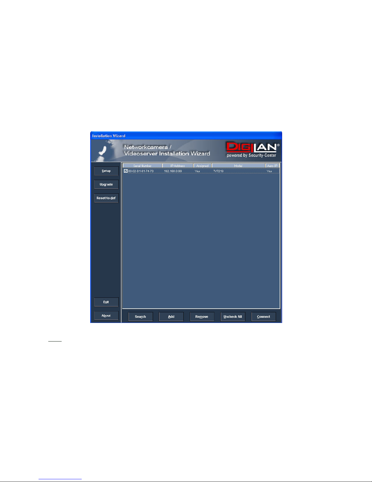
6. Following the program start, the Installation Wizard automatically searches for a connected network
camera.
7. If no camera is found in the first search, click “Search” for a new search.
Note:
The IP addresses shown in the “Current IP Address” field reflect those on the local network. They may be from the
DHCP server. If there is no DHCP server, the camera will try to find a free IP address (this takes from 15 seconds to
3 minutes, depending on the LAN status). The method of finding an IP address is seeking from 192.168.0.99, to
192.168.0.254. If any of the address inside this range is free, the network camera will be assigned to this IP
address, and its subnet mask would be 255.255.255.0. If none of the addresses is free, the network camera will try
the range from 192.168.0.2 to 192.168.0.98. After an IP address is assigned to the camera, the “Activity” status
LED blinks.
Note: If no camera is found via the manual search, change the network settings of your PC as described in the
instructions.
Page 11
11
8. Select one of the camera models found.
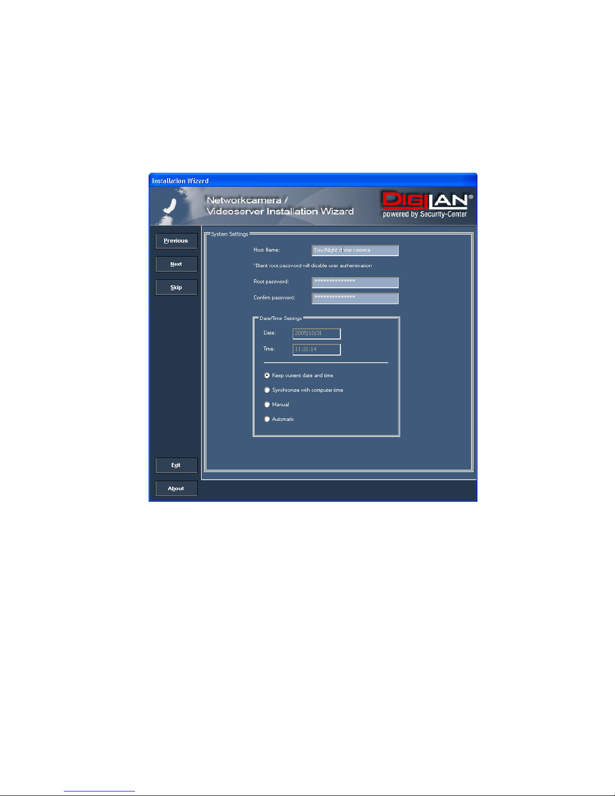
9. Click “Setup” to enter camera setup mode. If a password is required, use the device serial number
(no spaces, uppercase letters only). You can change the hostname, the administrator password and the
date/time settings of the camera. If you cannot access the settings, check the IP addresses of your
network adapter and your network camera. The IP addresses must be in the same subnet area. If
necessary, change the IP address of the network adapter (page 7).
Page 12
12
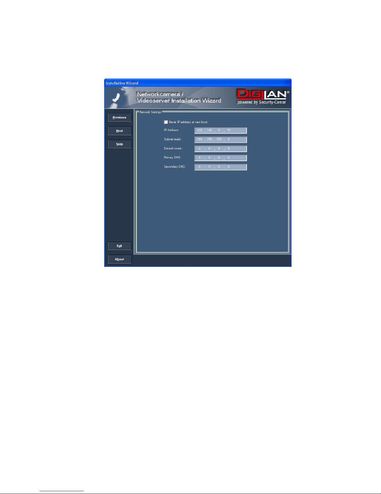
10. Now click “Next” to change the IP address of your network camera.
If you use a router in your network, enter this IP address (gateway) in the Default Router field.
11. If you disable “Reset IP address at next boot”, you do not have to reassign the IP address of this camera
following a power failure. Otherwise, you have to reassign the IP address after every camera restart.
12. Click “Next”.
Page 13
13
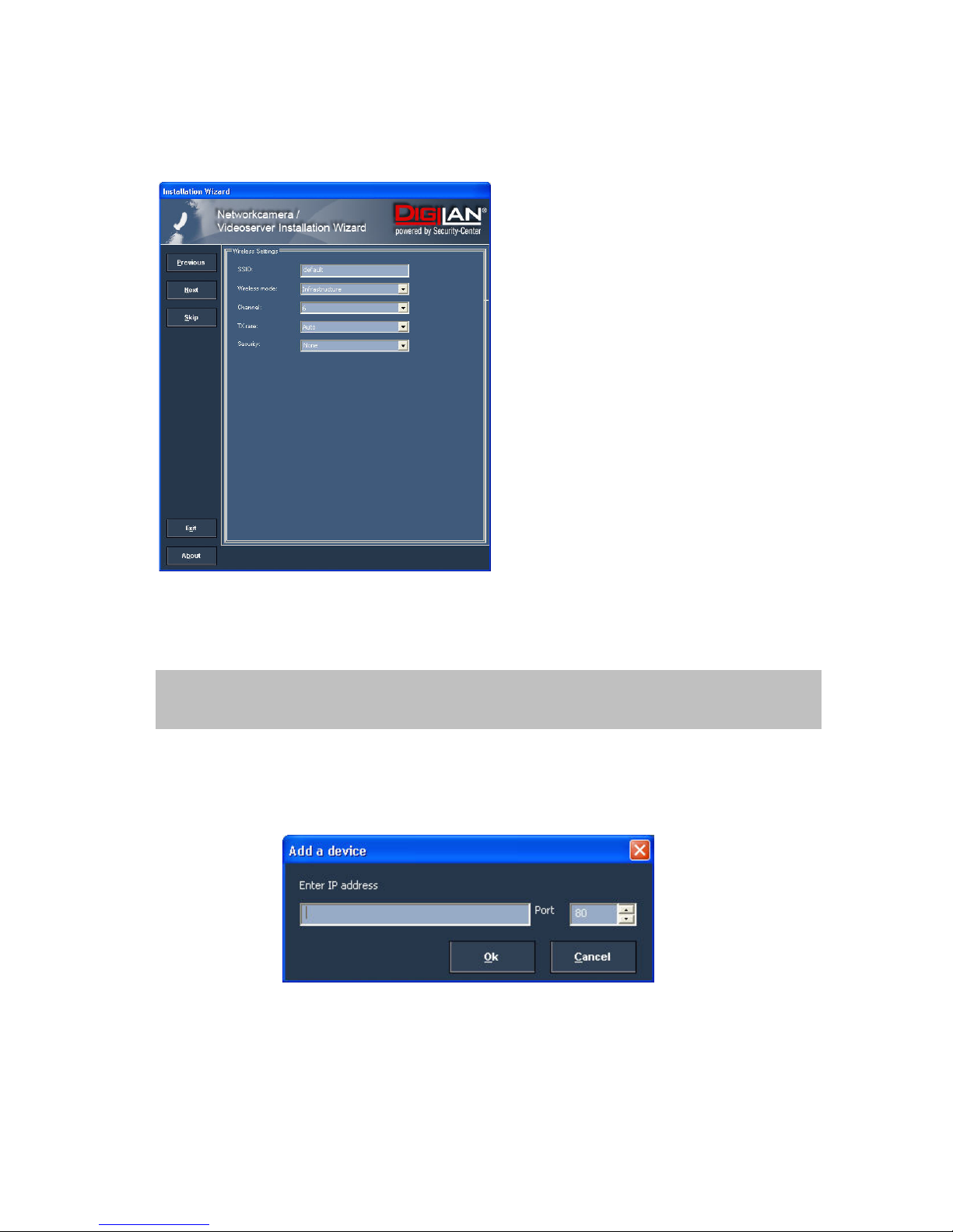
Now press the button “Skip” to skip the wireless LAN setup at this point. You will find more information under
“WLAN configuration”.
13. Follow the instructions on the screen to save or change your settings.
14. Click “Add” to add a network camera direct via the IP address or its domain name. You need this only if the
camera was not found by the automatic search.
15. Click “Remove” or “Uncheck all” to remove one or all network cameras from the menu.
16. Click “Connect” to set up a link to the selected network camera via the Internet Explorer.
The Installation Wizard is finished. Click “Previous” to change your settings. Click “Apply” to save your
input and transfer it to the selected device.
Page 14
14
Access to the network camera via the Internet Explorer
Defining a password to prevent unauthorised access
For security reasons, the administrator should define a new password immediately. After the new administrator
password is stored, the Network camera asks for the user name and password every time it is accessed. The
administrator can define up to twenty (20) user accounts. Every user has access to the Network camera, but not to
the system configuration. Some system-critical functions are reserved for the administrator, such as system
configuration, user administration and upgrading software programs. The administrator’s user name is always
root and cannot be changed. Following a password change, the browser displays an authentication window and
asks for the new password. After changing the password, you cannot restore the original administrator
password. Your only option is to reset all default factory settings/parameters.
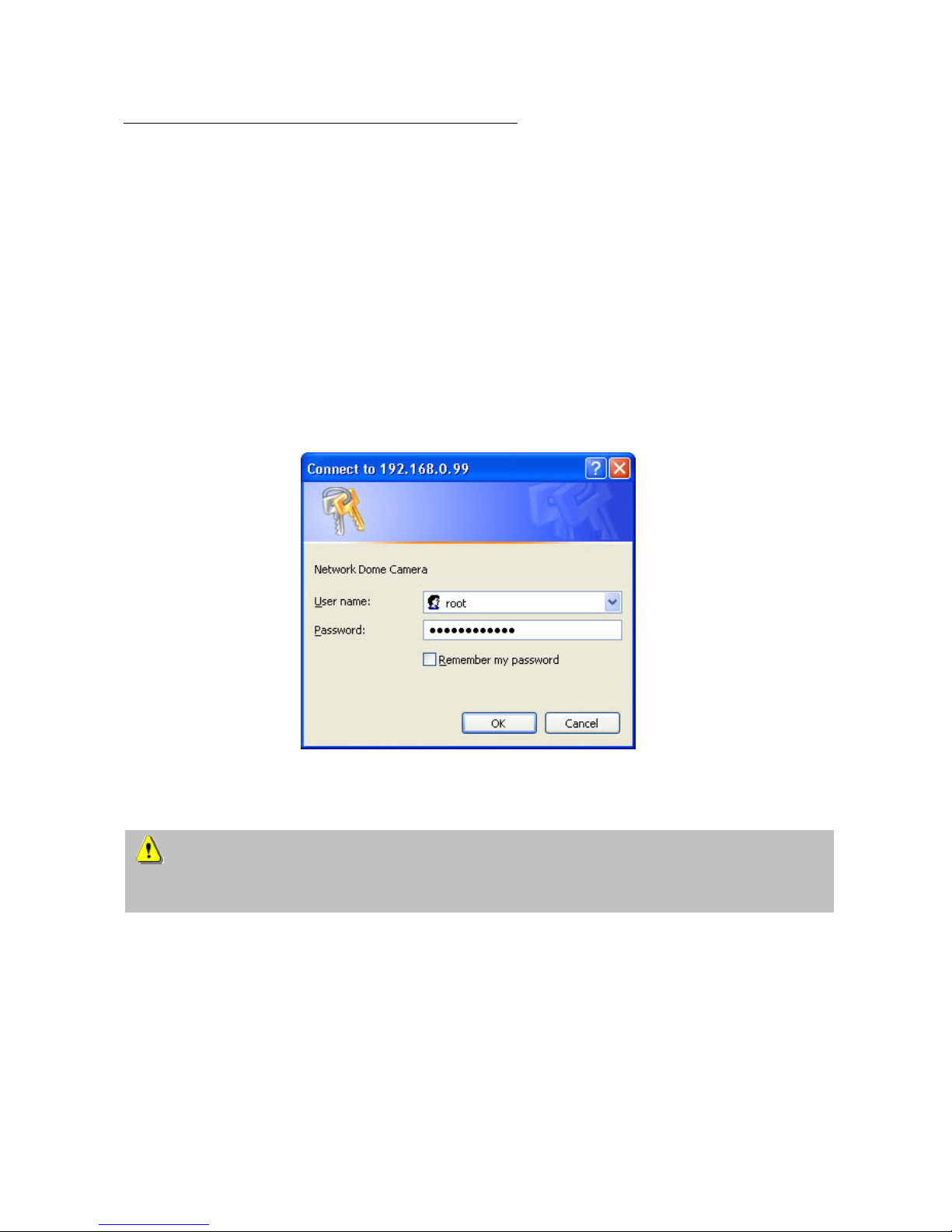
To enter the password:
Open the Internet Explorer and enter the IP address of the camera
(e.g.: <http://192.168.0.99>).
You are prompted for authentication:
Î You are now connected with the Network camera and can see a video stream.
Note: It may happen that your PC’s security settings prevent a video stream. You can change the security
settings to a lower level under “Tools/Internet Options/Security”. Make sure you enable Active X Control
Elements and Downloads.
Page 15
15
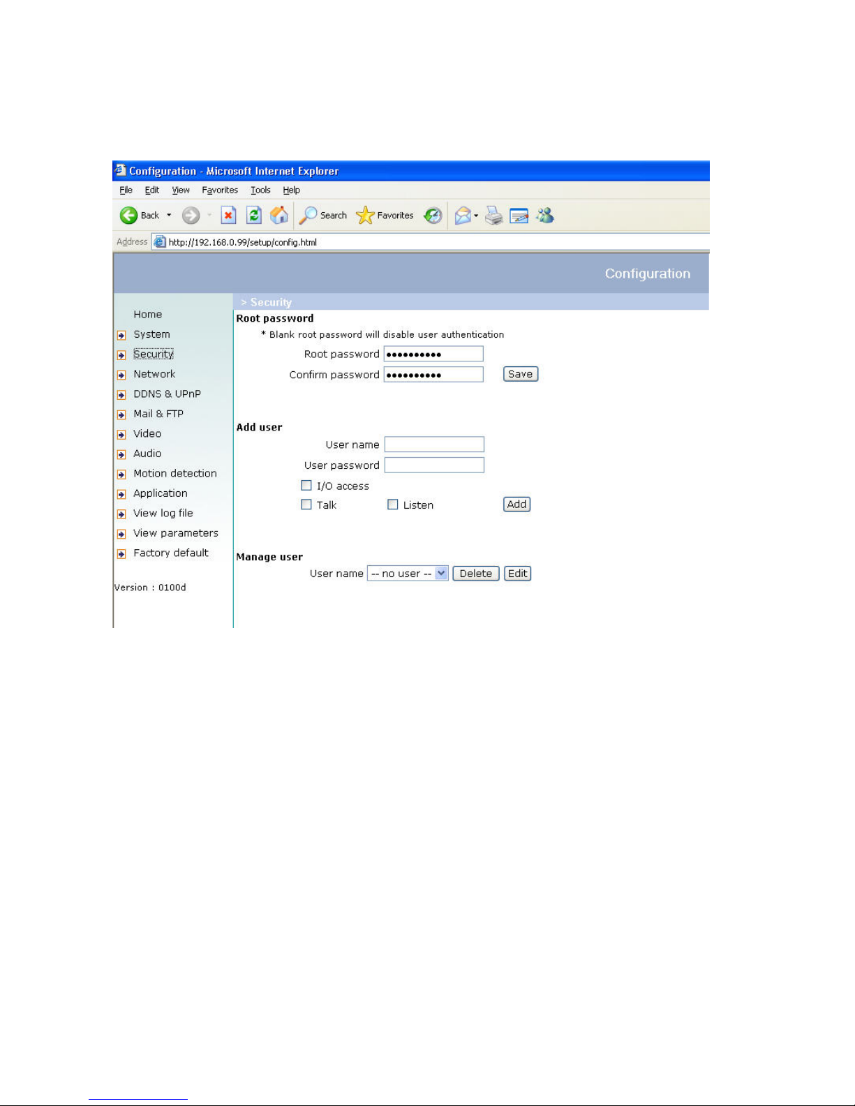
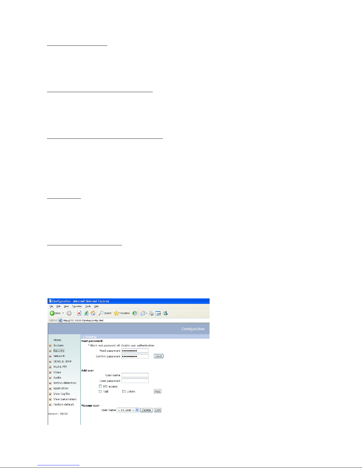
Changing the administrator password
Click “Configuration” and then “Security”.
Under “Root password”, enter the administrator password and confirm it under “Confirm password”.
Click “Save”.
The new administrator password is saved.
Click “HOME” in the column on the left to exit configuration.
Page 16
16
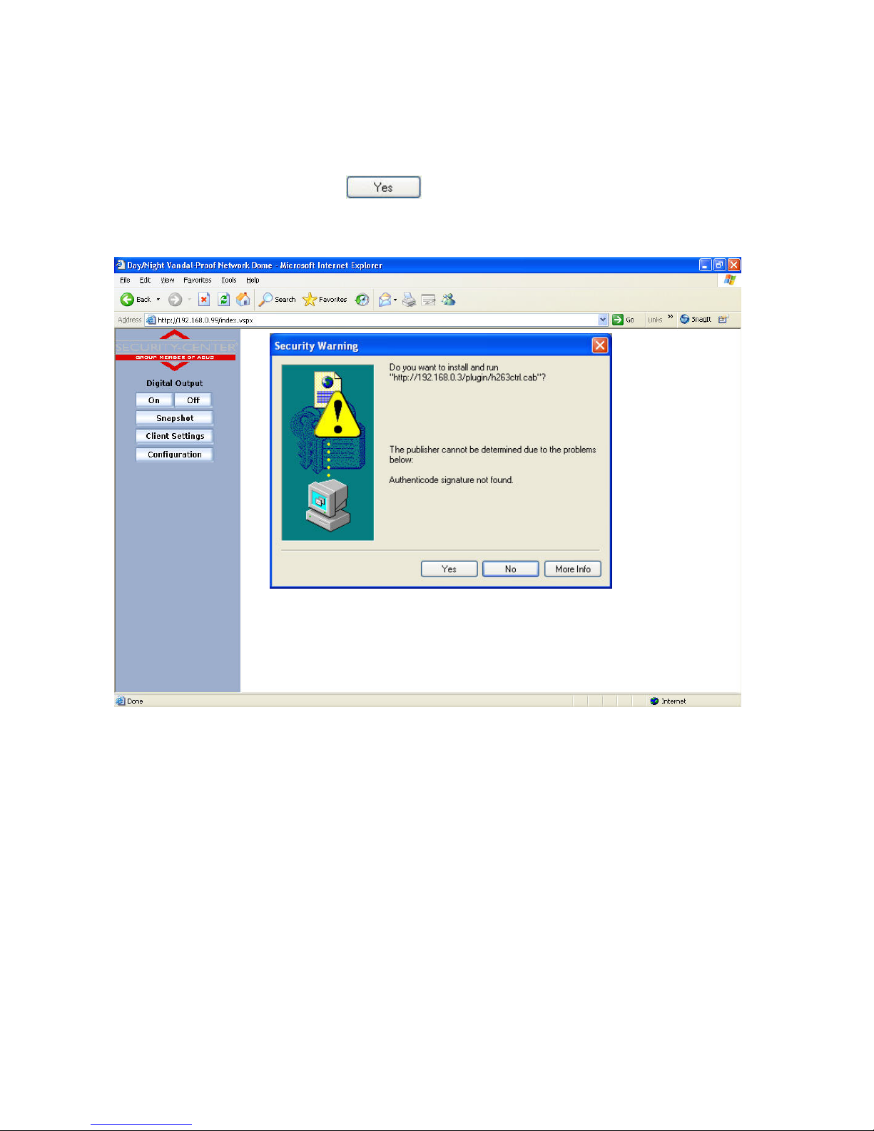
Installing the plug-in
When you first access the Network camera under Windows, the web browser may ask for the installation of a new
plug-in for the Network camera. This query depends on the Internet security settings of your PC. If the highest
security level is set, the PC will refuse any installation and any attempt at execution. This plug-in is used for video
display in the browser. To continue, click
. If the web browser prevents continuation of the installation,
open the Internet security settings and reduce the security level or consult the IT administrator or network
administrator.
Page 17
17
Basic user functions
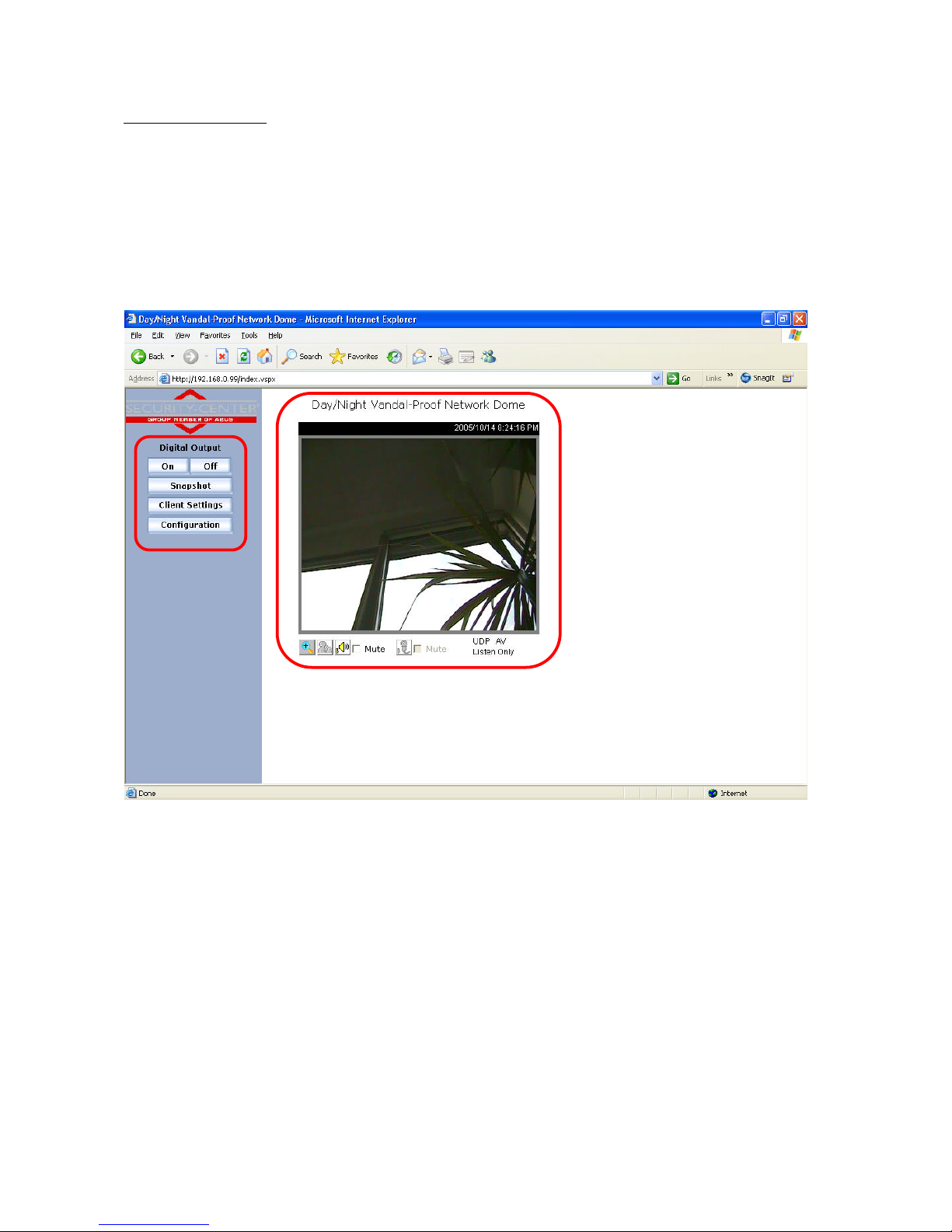
Main window and camera view
The view of the main page consists of two parts:
Configuration: The camera can be configured via this user interface.
Camera view: Camera video stream
Click the configuration link on the left of the picture to open the configuration page.
Page 18
18
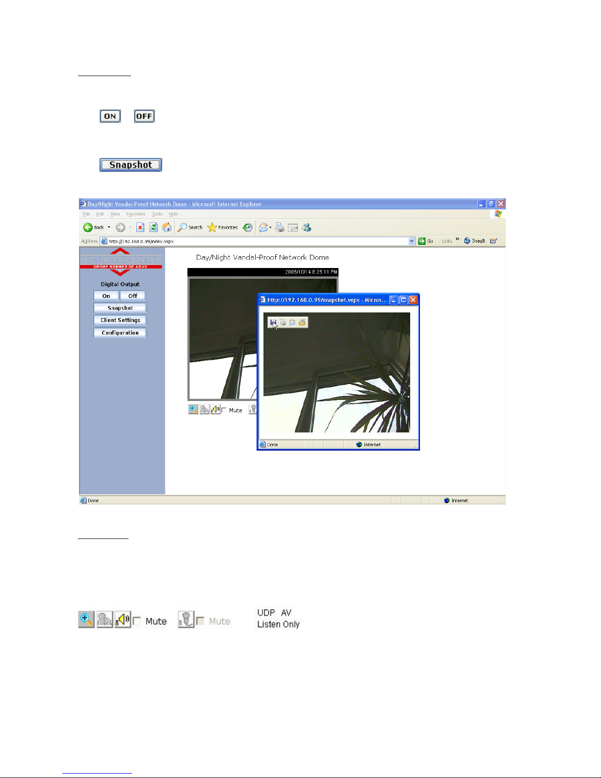
Configuration
Digital Output
Click
or to switch the relay output on/off.
Snapshot
Click
. The web browser displays a new window containing the snapshot. To save the snapshot,
either left-click it and then click the diskette icon or right-click it and select Save from the context menu.
Camera view
The information bar at the top of the camera view shows the assigned caption and the current date/time. The
information bar at the bottom of the camera view shows the current streaming mode and audio transmission mode.
You can push/toggle the talk button to talk to the remote server. The volume of speaker and microphone can also
be adjusted.
Zoom
Click the magnifying glass under camera view. The control field for digital zooming appears. Disable the Disable
Digital Zoom box and change the zoom factor with the slider.
Page 19
19
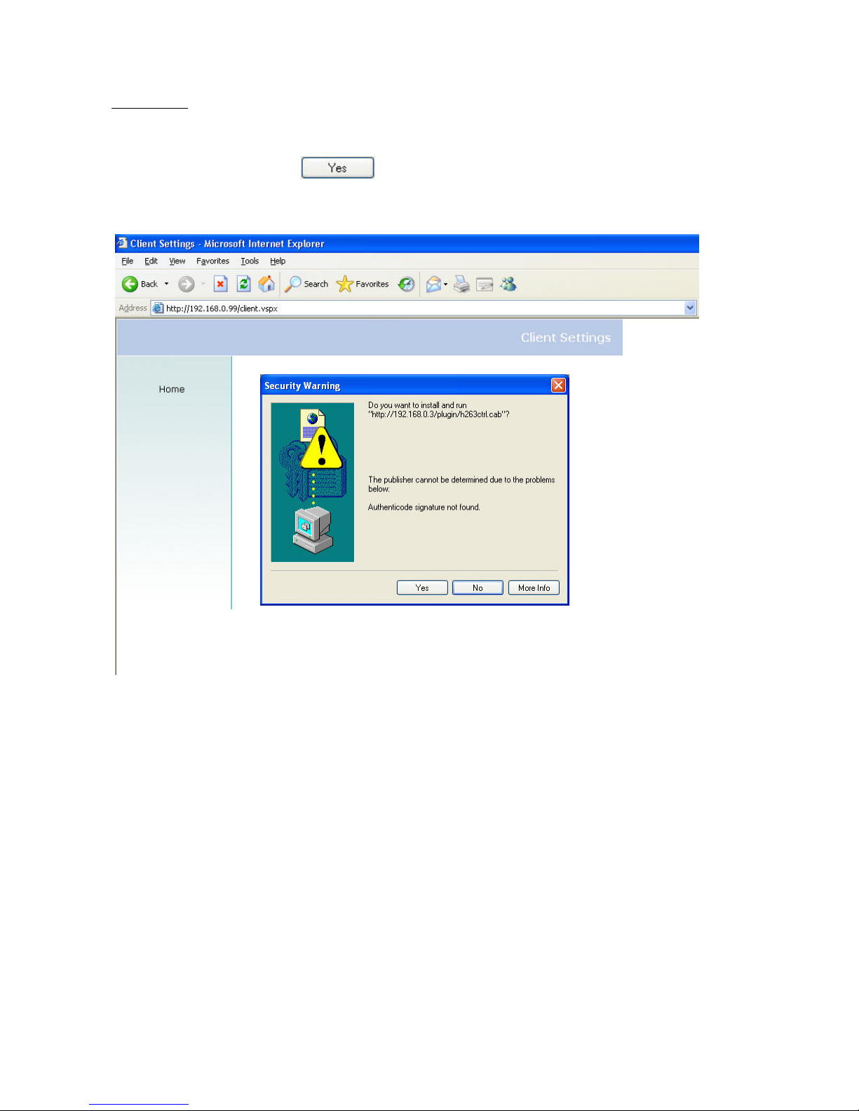
Client settings
When you first access the Connection Type page under Windows, the web browser asks for the installation of a new
plug-in. This plug-in was registered at certification and can be used to change parameters on the Client settings
page. To install the plug-in, click
. If the web browser prevents continuation of the installation, open
the Internet security settings and reduce the security level or consult the IT administrator or network administrator.
Page 20
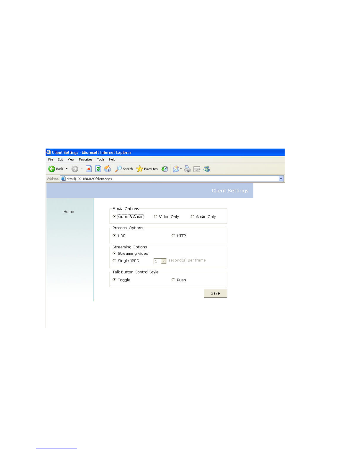
20
Two settings are available on the Client settings page. Under “Media Options”, you can disable the audio function.
Under “Protocol Options”, you can select a transmission protocol for data transfer between the client and the
server. Three protocol options are available for optimising the application: UDPand HTTP.
The UDP protocol gives you a larger number of realtime audio and video streams. However, some data packets
can be lost due to the large data volume in the network. Pictures can be unclear. The UDP protocol is
recommended if you have no special requirements.
Use the HTTP protocol if the network is protected by a firewall and only the HTTP port (80) is to be opened. In this
mode, no audio is transmitted.
The selection of the client is normally recommended in the following order: UDP – HTTP. When the Network
camera has been successfully connected, the “Protocol Options” box shows the selected protocol. The selected
protocol is registered in your PC and used for the next connection. After changing the network environment or if you
want to search again for the Network camera using the web browser, select the UDP protocol manually, save it and
then return to “HOME” to set up the connection again.
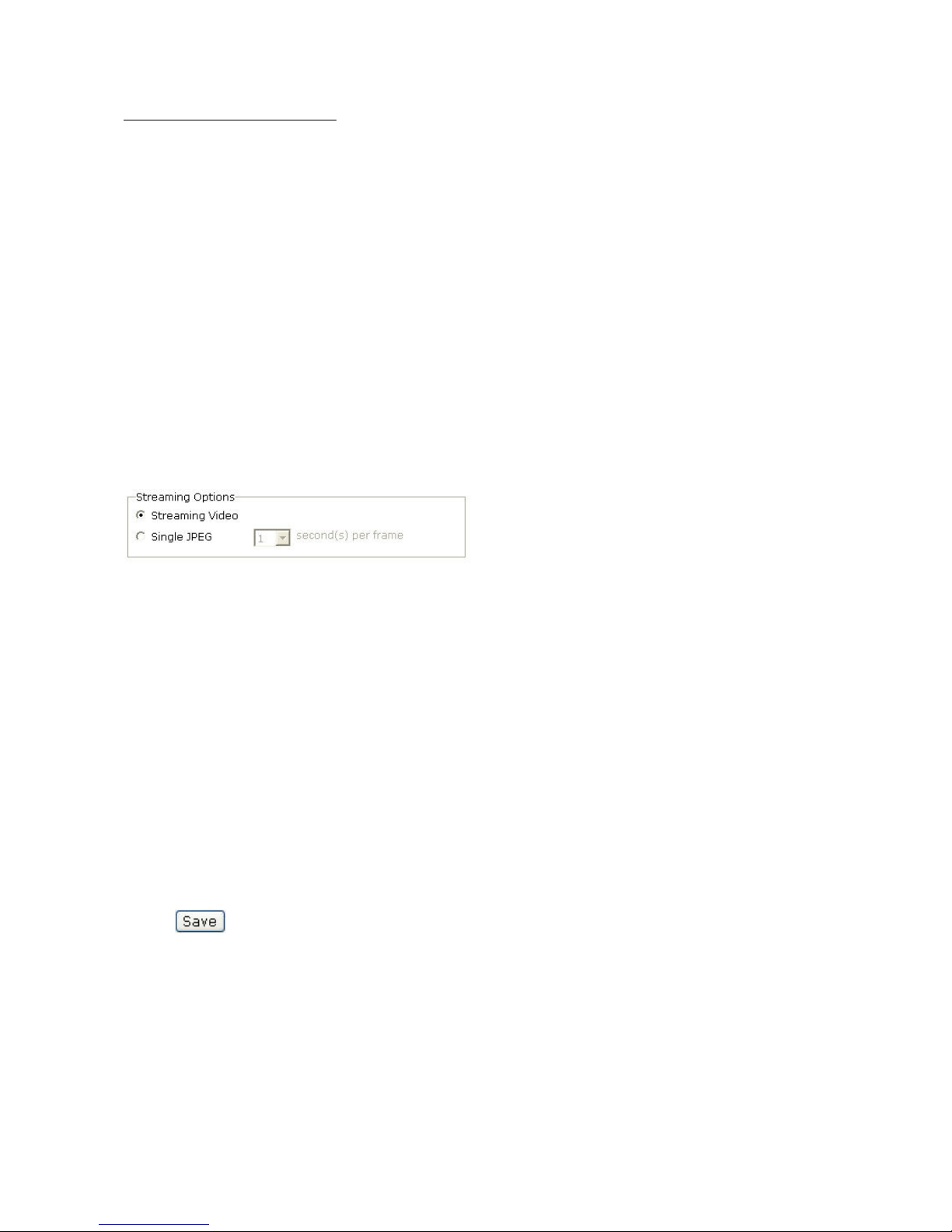
“Streaming Options” For users to select the video streaming types. Select “Streaming Video” option, the video
connection will keep alive to enable you to see smooth video, while “Single JPEG” option will let you see the video
in JPEG format by client periodic update the JPEG image from server according to the “Frame rate” settings.
“Talk Button Control Style” For the user to determine whether to “click once and talk” or “push to talk”.
<url> http://<Network Camera>/protocol.html
Network Camera is the original IP address or the hostname of the Network camera.
Page 21
21
Administrator settings
Configuration / video
Best performance is produced by the maximum frame rate with best video quality and minimum network bandwidth.
The six factors “Size”, “Maximum frame rate”, “Video codec type”, “Key frame interval”, “Fix bit rate” and “Fix
quality” on the video configuration page are correlative to allow for achieving the best performance that is possible.
For high frame rates
To obtain a good visual realtime effect (more than 20 frames/s), the network bandwidth must be sufficiently large. If
the network bandwidth is higher than 1 Mbps, the value for the “Fix bit rate” must be set to 1000Kbps or 1200Kbps
and the “Fix quality” to the highest quality. In the PAL system, the maximum frame rate is 25, and in the NTSC
system, 30 frames per second. If your network bandwidth is more than 384Kbps, you can fix the bit rate according
to your bandwidth and the maximum frame rate to 25 or 30 fps (frames per second). If the pictures in your
environment are changed drastically, you can reduce the maximum frame rate to 20 frames per second to set the
data transmission rate lower. This gives you a better video quality, and the human eye cannot distinguish between
20, 25 and 30 frames per second. If the network bandwidth is less than 384 Kbps, adjust the “Fix bit rate”
according to the bandwidth and try to get the best performance by fine-tuning the “Maximum frame rate”. In a
“slow” network, a high frame rate results in unclear, distorted images. Another way to improve quality is to select
“Half” in the “Size” option, or “Half x 2” for a larger view of the pictures. Video quality also depends on the number
of users in the network. Performance can also be affected by a bad connection and by a restriction of the network
burst.
In multi-user environment, the user who has poor network performance will receive only the key frame in MPEG4
format. Try to reduce the key frame interval can improve the frame rate for poor network performance, but the
penalty is the increasing of network traffic. If the server is running on the Internet, select “Improve efficiency in the
multi-user environment” will improve the efficiency in the multi-user environment.
Page 22
22
For higher-quality pictures
For best video quality, set “Fix quality” to “Detailled” or “Excellent” and the “Maximum frame rate” so that it
corresponds to the bandwidth of your network. If your network is slow and you get “broken” images, go to the HTTP
protocol under “Protocol Options” and select a more suitable transmission mode. Pictures can also be affected by
a time delay due to a slower connection. The more users in the network, the greater this time delay.
For high frame rates with high-quality pictures
If you have a broadband network, set “Fix bit rate” to “512Kbps” or higher and leave “Fix bit rate” unchanged. You
can also set the bandwidth according to the actual network speed or the frame rate. Start with 25 frames per
second and reduce this setting until you get the best performance. However, do not reduce it to less than 15 frames
per second. If the picture quality is not improved, select a lower setting for “Fix bit rate”.
Select Motion-JPEG (MJPEG) for video codec type
The network camera is a camera with dual video codec, MPEG4 and MJEPG. If MJEPG is selected the camera will
transmit video data in JPEG format. Therefore, it requires higher bandwidth to view smooth video. General
speaking, each normal sized JPEG image would be 3k~12k bytes, depending on the selected video quality and
contents. Together with the frame rate selected, the administrator can control the bandwidth of each connection.
Protecting the Network camera with a password
Root password
The DIGI-LAN Network camera is delivered without password. In this case all users have access to the Network
camera, including its configuration, as long as they know the IP address. If other users are to have access to the
Network camera, you should therefore assign a password to the camera. To activate protection, enter a new
password. The administrator is identified with this password.
Opening accounts for new users
Under “Configuration”, select “Security”. Now go to the Add user section.
Add an account with user name and password for a second user. You can define up to twenty accounts for other
users of the Network camera. The camera checks only the access permission of the corresponding user name and
password. This means that two or more users can use the same account at different levels. An option for access to
the relay “I/O access” is available for every account.
Page 23
23
More flexible options for the viewer
Allow “demo” account to view:
If you want to have a guest account for viewers only, you just need to add a user without password and disable all
privileges. Share the account to you friends.
Format of a multimedia website
Demo on two or more pages – medium-scale service
The Network camera allows up to ten online visitors simultaneously. Following installation, you focus the Network
camera on a picture and inform the visitors of the web browser address. Caution: Keep your guest list on the
security configuration page to prevent visits by unwanted visitors.
Product demo for e-Business – large-scale service
If the number of visitors exceeds the limit, the Network camera enables the pictures to be viewed as snapshots in
JPEG mode. These pictures are displayed as stills and updated automatically. This requires a script function that is
supported by the web browser.
1. On the homepage, click “Client settings”.
2. Select “Single JPEG” in “Streaming Options”,
3. Set the snapshot interval for automatic updating of the still picture. The greater the snapshot interval, the better
the snapshot mode works for more viewers.
If you want to extend the function for a larger number of visitors, the host server must be capable of handling large
traffic volumes in the network in order to be able to update the pictures from the Network camera.
If the website has an FTP service
Define the Network camera as an FTP client. Access to the Network camera depends on the number of visitors; the
picture quality remains constant.
1. On the homepage, click “Configuration”.
2. In the left column, click “Mail & FTP”.
3. Enter the FTP-specific settings, including the server, user name, and password, plus the path for uploading, if
required by the website.
4. Click
; the system is restarted.
Page 24
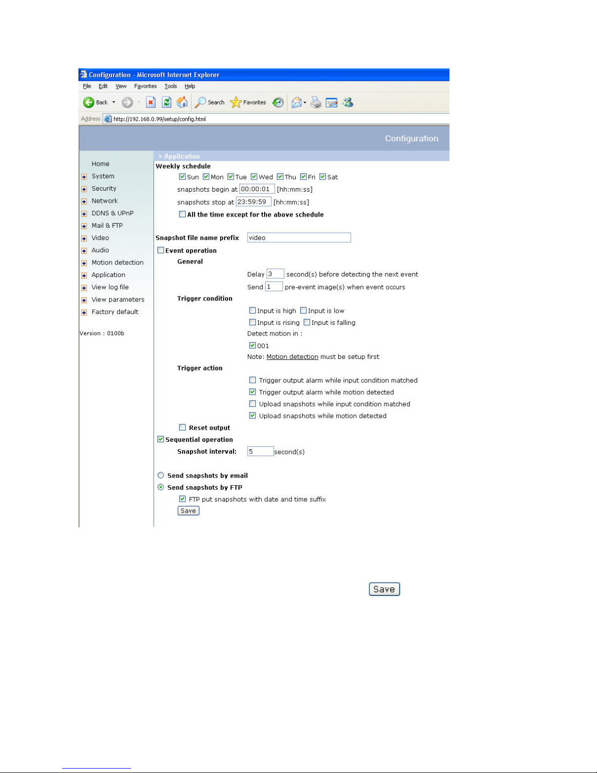
24
5. In the left column, click “Application”.
6. To upload the pictures, select the weekday and the daily schedule.
7. Select “Sequential operation” and set the interval.
8. Unselect the FTP without the date/time suffix as transfer method and click
9. The image file uploaded to the web is named video.jpg. Make sure that the file is uploaded to the right folder.
10. Prepare a homepage with the integrated picture reference for the image file previously uploaded via FTP.
Page 25

25
If no FTP service is available in the web
An automatically updated homepage can be used for occasional retrieval of the latest pictures from the Network
camera. You get the best performance by using a free website provider, since the FTP service can be restricted.
Alarm inputs/outputs
Configuration / application
The administrator can combine options on the application page to permit the running of a large number of security
applications. Two inputs, e.g., for motion detection, are available. There are also two outputs that react to such
events, including uploading of snapshots via the Internet and switching other connected actors. You can use either
FTP or e-mail to upload snapshots. Both e-mail and FTP use the network settings on the homepage. For
specifications of a detailed configuration, see the “System configuration” section.
<html>
<head>
<title>Example – auto refresh page</title>
</head>
<body>
<p align=left>
<font size="7" face=”Comic Sans MS" color="#FF0000">MiniAVServer
Demo</font>
</p>
<p align left>
<!—Begin of scripts to auto refresh the image. Change the IP address in the
image URL and refreshrate if necessary.-->
<script language=javascript>
var RefreshRate=1;// Refresh Rate in Seconds
var SourcePic="http://62.153.88.101/cgi-bin/video.jpg";
var WidthPic=352;
var HeightPic=288;
function refresh(){
document.images["Picture"].src=SourcePic+"?"+new Date();
setTimeout('refresh()', RefreshRate*1000);}
document.write('<img src="'+SourcePic+'" height="'+HeightPic+'"
width="'+WidthPic+'" name="Picture">');
if(document.images) window.onload=refresh;
</script>
<!—-End of scripts to auto refresh the image.-->
</p>
</body>
</html>
Page 26
26
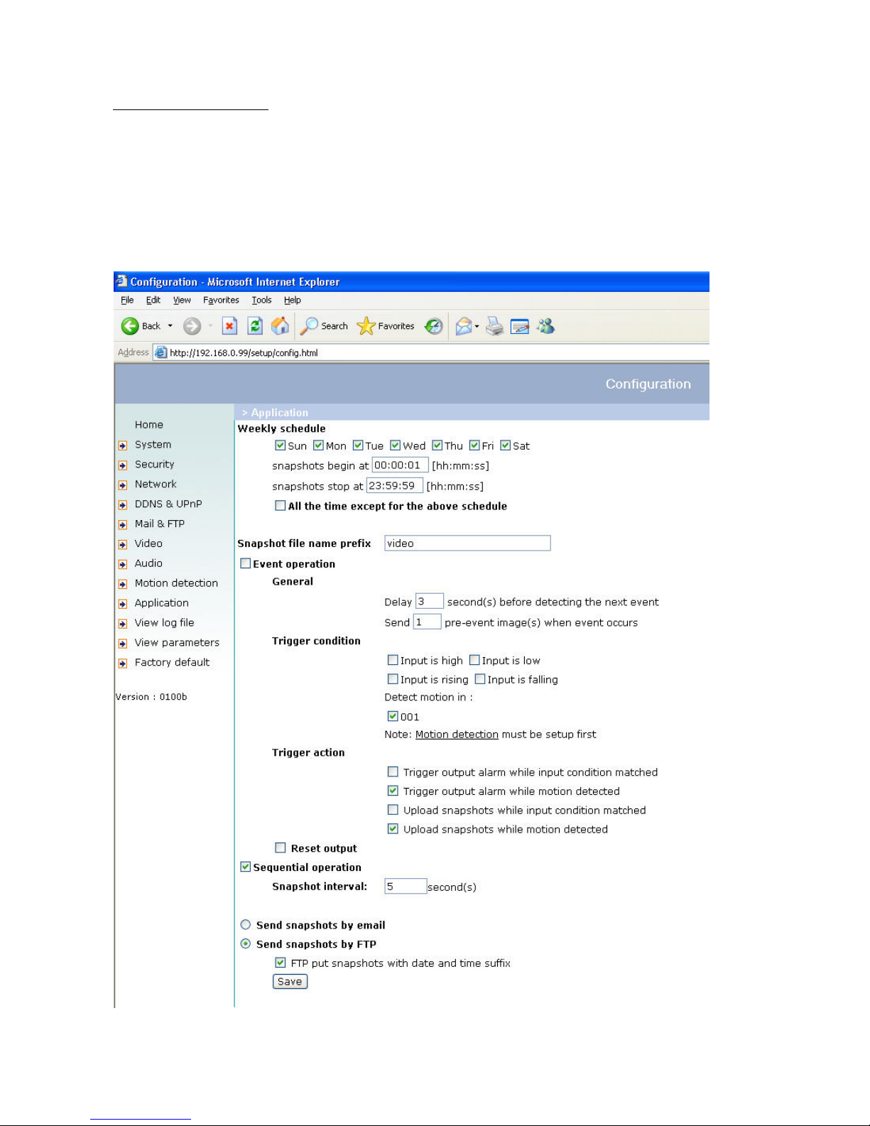
Time-controlled surveillance
1. On the homepage, click “Configuration”.
2. In the left column, click “Application”.
3. Click the boxes next to the weekdays you require and define the time period under “Snapshots begin at” and
“Snapshots stop at” for daily supervision of the trigger conditions.
4. Enable “Event operation”. The trigger condition can be set to detect series of motions or the status of the
connected device.
5. The delay before detecting the next event is used to prevent continuous error display following the original event.
6. The delay for recording a snapshot after the event is used for recording the direction of moving objects.
Page 27
27
Integrated video sensor
If no external sensor is available, the administrator can use the integrated motion sensor to monitor movement and
send snapshots by e-mail for inspection.
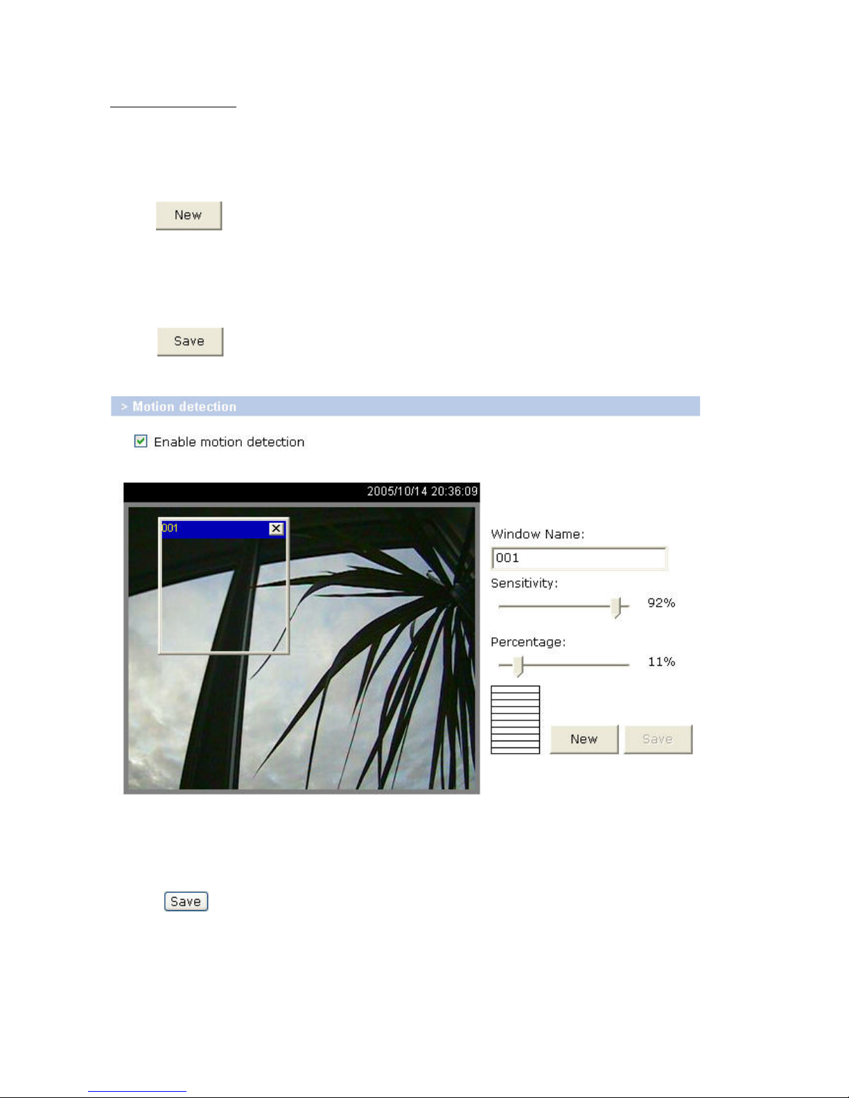
1. In the left column, click “Motion detection”.
2. Enable “Enable Motion detection”.
3. Click
to keep a new window ready for supervising the video.
4. Enter a new name to identify the new window.
5. Click a corner of the window, keep the mouse button pressed, and adjust the size of the window for motion
detection or move the window.
6. You can fine-tune the camera with “Sensitivity” and “Percentage”. The higher the “Sensitivity”, the smaller the
changes that can be detected in the picture sequence. The lower the “Percentage”, the smaller the objects that can
be differentiated in a picture.
7. Click
to activate the bar graph (activity). Green means that the motion sequence is lower than the
level set by the administrator, and red means that the motion sensor has been triggered.
8. In the left column, click “Application”.
9. Under Event operation/Trigger condition/Detect motion in, select the window name.
10. Enable “Upload snapshots while motion detected” to transfer the snapshots by e-mail.
11. Enable “Send snapshots by email”.
12. Click
to activate the settings (activity).
Page 28

28
Updating the software version
You can download the latest software from the website. A user-friendly update wizard (installation wizard) is
provided for updating the Network camera software. Only the administrator can start the update function. To
update the system:
1. Download the firmware file with the name TV721X_english.pkg from the corresponding products folder.
2. Start the update wizard and follow the instructions. For details, see the instructions of the update wizard.
3. The complete procedure finishes in a few minutes, and the system is automatically rebooted.
If there is a power failure during the write process of the flash memory, the program in the
memory of the security network camera may be irreparably damaged. If the security network camera
cannot be correctly restarted following the update, consult your dealer’s technical support.
Page 29
29
System configuration
Only the administrator has access to system configuration. The following sections explain each element in the left
column. Specific tasks on the Options page are printed bold. The administrator can enter the URL under the picture
to jump direct to the pictures page of the configuration. For setting specific options via the URL, see Appendix C.
“url” http://”Network Camera”/setup/config.html
“Network Camera” is the domain name or original IP address of the security network camera.
“url” http://”Network Camera”/setup/system.vspx
“Network Camera” is the domain name or original IP address of the security network camera.
Page 30
30
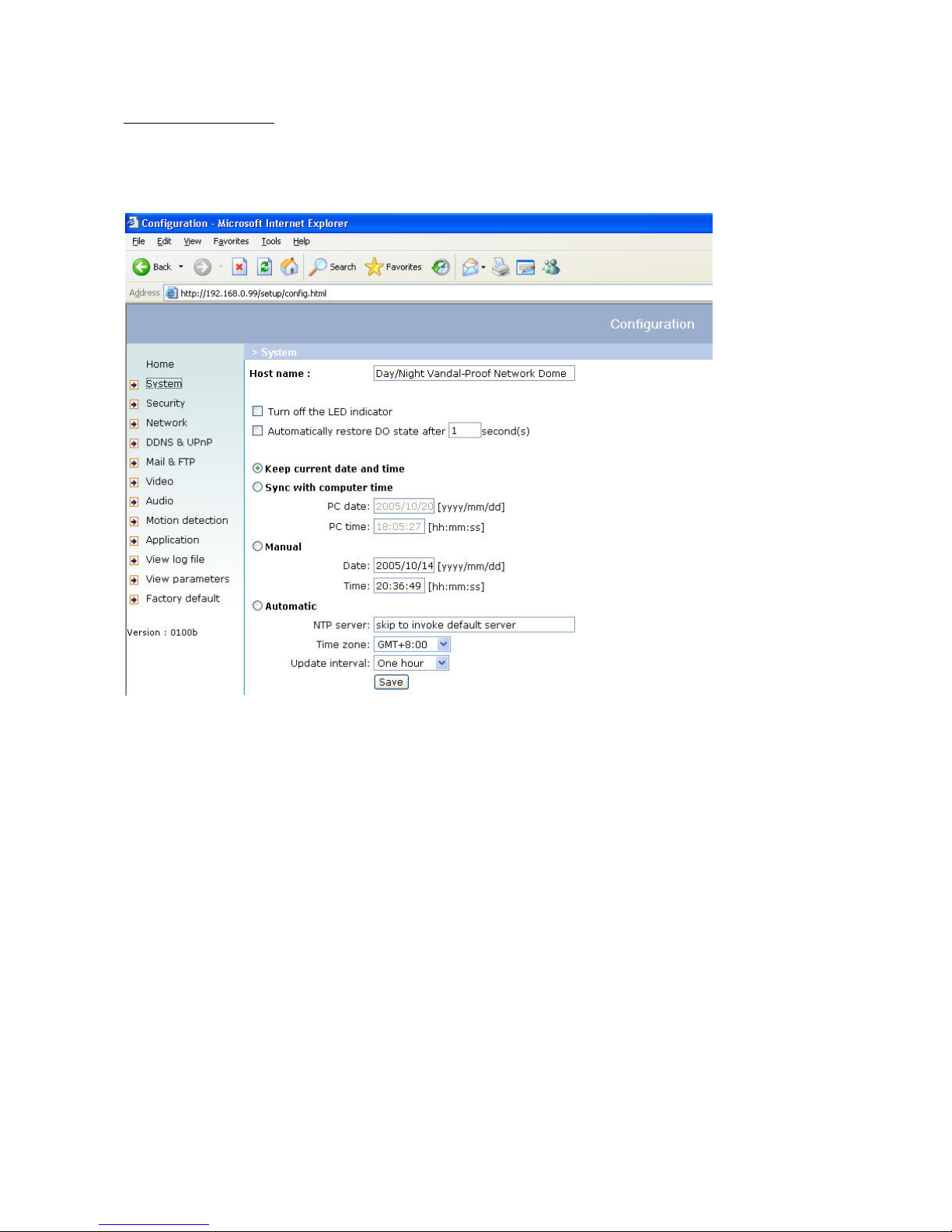
System
„Host name“ The text represents the title of the homepage.
„Turn off the LED indicator“ Select this option to switch of the LED on the rear of the camera. This prevents other
persons knowing that the camera is in use.
„Keep current date and time“ Click this option to keep the current date and time of the security network camera. An
internal realtime clock stores the date and time after the system is switched off.
„Sync with computer time“ Synchronises the date and time of the security network camera with the local computer.
The read-only date and time of the PC are displayed following updating.
„Manual“ Sets the date and time according to the administrator’s input. Note the date/time format when entering in
the respective fields.
„Automatic“ Synchronises the date and time with the NTP server via the Internet every time the security network
camera is switched on. This is not possible if the respective time server cannot be reached.
„NTP server“ Assigns the IP address or the domain name of the time server. If you leave this text box empty, the
security network camera is connected to the default time servers.
„Time zone“ Sets the time according to the time server for local settings.
“Update interval” Select hourly, daily, weekly or monthly update with the time on the NTP server.
Don’t forget to click
to make your settings take effect; otherwise, the time is not synchronised.
Security
„Root password“ For changing the administrator password by entering a new password. For security reasons, the
passwords entered are represented by asterisks. After
is clicked, the web browser prompts the administrator
to enter the new password for accessing the network camera.
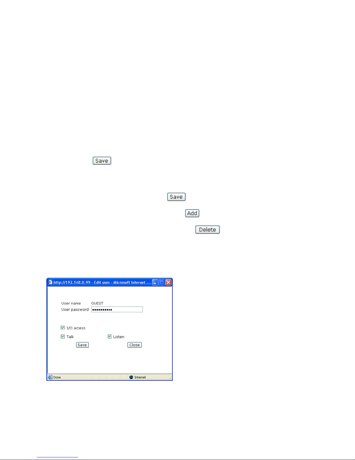
„Add user“ Enter the new user name and password and click . The new user is displayed on the list of user
names. Up to twenty user accounts can be defined. You can assign “I/O access”, ”Talk” and “Listen” to every user.
„Delete user“ Open the list of user names, select a user and click
to delete this user.
“I/O access” Allows user to control the DO (Relay output) and get status of the DI (Digital input).
“Talk” Allows user to talk to the server
“Listen” Allows user to listen from the server.
“Delete user” Pull down the user list to find the user’s name and press “Delete” to complete.
“Edit user” Pull down the user list to find the user’s name and press “Edit” to edit the user’s password and privileges.
“url” http://”Network Camera”/setup/edituser.vspx
“Network Camera” is the domain name or original IP address of the security network camera.
“url” http://”Network Camera”/setup/security.vspx
“Network Camera” is the domain name or original IP address of the security network camera.
Page 31

31
Network
All changes made on this page cause a system reboot so that they can take effect. Make sure that the fields are
correctly filled before you click
.
„Get IP address automatically“ This can be tedious having to perform software installation whenever the network
camera starts. Therefore, once the network settings, especially the IP address, have been entered correctly, select
“Use fixed IP address” then the network camera will skip installation at the next boot. The network camera can
automatically restart and operate normally after a power outage. Users can run installation wizard to check the IP
address assigned to the network camera.
General
„IP address“ This is needed for network identification.
„Subnet mask“ Defines whether the destination is in the same subnet. The default value is “255.255.255.0”.
„Default router“ Gateway for transmitting pictures to another subnet. An invalid router setting prevents transmission
to these destinations in different subnets.
„Primary DNS“ Server of the primary domain name with which the hostnames are converted into IP addresses.
„Secondary DNS“ Server of the secondary domain name for generating a reserve copy of the primary DNS.
HTTP
„HTTP port“ This port can be different from the standard port 80. If this port is changed, users must be informed to
ensure a successful connection. Example: If the administrator changes the HTTP port of the security network camera
with the IP address 192.168.0.99 from 80 to 8080, users have to enter “http://192.168.0.99:8080” in the web
browser instead of “http://192.168.0.99”.
Data flow
„UDP audio channel port“ This port can be different from the standard port 5002 if this is blocked by a firewall.
„UDP video channel port“ This port can be different from the standard port 5003 if this is blocked by a firewall.
“url” http://”Network Camera”/setup/network.vspx
“Network Camera” is the domain name or original IP address of the security network camera.
Page 32

32
WLAN configuration
“SSID” (Service Set Identifier) The name that identifies the wireless network. The access point and the WLAN network
camera must use the name SSID. The factory setting is “default”. IMPORTANT: The max. length is 32 characters;
do not use: “ , ”, <, > and spaces.
“Wireless mode” Select one of the following:
“Infrastructure” The network camera is connected to the network via an access point.
“Ad-Hoc” In this mode, the network camera can communicate direct with another network adapter
(network card). A so-called Peer-to-Peer environment is set up.
“Channel” In infrastructure mode, the channel used is selected automatically by the camera. In Ad-Hoc mode, the
channel must be set manually according to the other network adapter.
“TX rate” Set the maximum transmission speed in the network. In the factory, the speed is set to select automatically
(“auto”), and the camera always tries to reach the highest transmission speed according to the environment.
“Preamble” A so-called preamble is set before each data packet. This preamble is used to synchronise the receiver
and the sender. With a “short preamble”, the synchronisation length is shorter and therefore not so secure.
“Security” Select the encryption method:
“None” No encryption selected.
“WEP” (Wired Equivalent Privacy) A 64- or 128-bit key is used for encryption (HEX or ASCII). For
communication with other equipment, these keys must be the same on both devices.
“WPA-PSK” (Wi-fi Protected Access – Pre Shared Keys) With this method, dynamic keys are used. As
encryption protocols, TKIP (Temporal Key Integrity Protocol) or AES (Advanced Encryption Standard) can be
selected. A so-called Pre-Shared Key must be defined.
“Auth mode” Authentication mode: Select one of the following methods:
“Shared” This mode permits communication only with equipment using the same WEP key.
“Open” The key is communicated over the whole network.
“Key length” Select 64 or 128 bit.
“Key format” Key format
“HEX” Hexadecimal format
“ASCII” ASCII format
“Network key” For different key formats, different key lengths are expected.
64 Bit: 10 hex digits or 5 characters
128 Bit: 26 hex digits or 13 characters
256 Bit: 58 hex digits or 29 characters
IMPORTANT: If you want to use characters 22 ("), 3C (<) or 3E (>), you cannot use ASCII format.
“Pre-Shared-Key” Enter this key in ASCII format with a length of 8 ~ 63 characters.
Page 33

33
<URL> http://<Network Camera>/setup/wireless.vspx
<Network Camera> is the domain name or original IP address of the network camera.
Incorrect settings may prevent access to the camera. If the system can no longer be addressed,
read the notes on restoring the factory settings in the appendix.
Page 34

34
DDNS and UPnP settings
„Enable DDNS“ Enables the DDNS function.
„Provider“ The provider list contains four hosts that provide DDNS services. Connect to the service-provider’s
website to make sure that the service is available.
„Host name“ This field must be completed if you want to use the DDNS service. Enter the hostname registered with
the DDNS server.
„Username/Email” The user name and the e-mail address must be entered in this field to set up a connection to the
DDNS server or to inform users about the new IP address. Important: If you enter a user name in this field, you must
enter a password in the next field.
„Password/Key“ To be able to use the DDNS service, enter the password or the key.
„Enable UPnP“ Enables/disables the UPnP function. If UPnP is disabled, the camera cannot be found in the network
environment under MS Windows XP. If the UPnP network component is installed under Windows XP, the hostname
of the security network camera in the network environment is displayed with an IP address in brackets. Example:
Security network camera (192.168.0.96). This means: The hostname of the security network camera is “Security
network camera”, and the IP address of the security network camera is 192.168.0.96.
Click this button to save the current settings for the DDNS service and the UPnP function.
“url” http://”Network Camera”/setup/ddnsupnp.vspx
“Network Camera” is the domain name or original IP address of the security network camera.
Page 35

35
Mail & FTP
SMTP
If the SMTP server supports SMTP authentication, the user has to enter a valid user name and password to send an
e-mail via the server.
„1st SMTP mail server“ Domain name or IP address of the external e-mail server.
„1st SMTP account name“ Permitted user name for external e-mail server.
„1st SMTP password“ Permitted password for external e-mail server.
„1st recipient email address“ E-mail address of recipients of snapshots or of the log file. Two or more recipient
names must be separated by semicolons (;).
„2nd SMTP mail server“ Domain name or IP address of another e-mail server (backup) if the first server cannot be
reached.
„2nd SMTP account name“ Permitted user name for backup e-mail server.
„2nd SMPT password“ Permitted password for backup e-mail server.
„2nd recipient email address“ E-mail address of recipient for backup server.
„Sender email address“ E-mail address of sender.
FTP
„Built-in FTP server port“ This port can be different from the standard port 21. The user can set this parameter to 1
to 65535. If this parameter is changed, the server port of the connection must be changed accordingly by the
external FTP client program.
„1st FTP server“ Domain name or IP address of the external FTP server. The following user settings must be correctly
configured for remote access.
“1st FTP server port” The port to access the external FTP server.
„1st FTP server user name“ Permitted user name for external FTP server.
„1st FTP server password“ Permitted password for external FTP server.
“1st FTP remote folder” Permitted folder for external FTP server. The character set must match that of the external
FTP server. If the virtual path is not mapped, some FTP servers cannot accept a slash in front of the path name. For
details, see the instructions for the external FTP server. The folder privilege must be open for uploading.
„1st FTP passive mode“ The security network camera is in the network protected by a firewall. A data connection for
FTP may not be permitted. If you select passive mode, the FTP can get round this restriction and permit snapshots,
so that the upload can continue. If you select passive mode, the security network camera can automatically try
active mode if the external FTP server does not support passive mode.
„2nd FTP server“ Domain name or IP address of the external FTP server.
“2nd FTP server port” The port to access the external FTP server.
„2nd FTP user name“ Permitted user name for backup FTP server.
„2nd FTP password“ Permitted password for backup FTP server.
„2nd FTP remote folder“ Permitted folder for backup FTP server.
„2nd FTP passive mode“ Setting of passive mode for the backup FTP server.
Page 36

36
“url” http://”Network Camera”/setup/mailftp.vspx
“Network Camera” is the domain name or original IP address of the security network camera.
Incorrect settings can result in malfunctioning. Change the configuration only if absolutely
necessary and consult the network administrator for the correct settings. Resetting and restoring
the original configuration is described in Appendix A.
Page 37

37
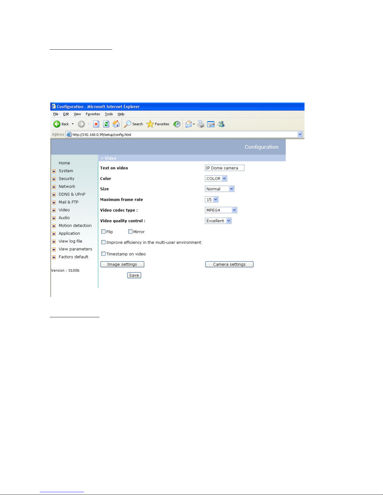
Video
„Text on video“ The text appears in the black bar above the video window with a timestamp. This timestamp (date
and time) is supplied by the security network camera, and the date and time are supplied by an integrated realtime
clock.
„Color“ Selects between colour and monochrome display.
„Size“ Five options are available for the three video sizes.
corresponds to a quarter of the size of
. corresponds to the same video size as , but with reduced
quality while requiring less bandwidth.
corresponds to a quarter of the size of .
corresponds to the same video size as , but with reduced quality while requiring
less bandwidth.
“Video codec type” It can be either MJPEG or MPEG4. In MJPEG mode, the video frames are independent. In
MPEG4 mode, there are I frames and P frames. To decode a P frame need information of the previous frame.
MPEG4 consumes much less network bandwidth than MJPEG.
Five parameters are available for setting the video quality.
Restricts the maximum frame
rate, which can be combined with
to optimise bandwidth use and video quality. If the user
wants to define bandwidth usage independently of the video quality,
and the desired bandwidth
must be selected. MPEG4 video are composed by I frames and P frames as the following sequence:
IPPPPIPPPPIPPPP. “Key frame interval” determines how many related P frames will appear after one I frame. Large
“Key frame interval” can reduce the bit rate, but cause image corrupt longer if there is packet loss while
transmission. “Fix bit rate” option and “Key frame interval” option are only available in MPEG4 mode. Video quality
can be affected due to sending the maximum frame rate within the restricted bandwidth if the pictures are fastmoving. To ensure video quality (quantising rate) independent of the network, a greater bandwidth is used to be
able to handle maximum frame rate during the transmission of rapidly changing pictures.
Rotates the video vertically.
Rotates the video horizontally. Select these options if the security network camera is installed upside down
or back to front.
“Improve efficiency in the multi-user environment” Check this option to improve efficiency in the multi-user
environment when running in the low bandwidth environment. But it will cause each connection slow a few minutes
when connection established.
“Time stamp on video” When selected the time stamp format is:
a) “Size” becomes Normal or Double, “Text on video” hh:mm:ss yy/mm/dd”
b) “Size” becomes half, “hh:mm:ss yyyy/mm/dd”
Page 38

38
“url” http://”Network Camera”/setup/video.vspx
“Network Camera” is the domain name or original IP address of the security network camera.
Picture settings
Click
to open another window in
which you can set the
, , and
the
of the video picture. Each field has levels from –5 to
+5. To check your settings, click
. To save the
picture parameters, click
. To discard your changes,
click
.
Camera settings
Click on “Camera settings” button, the Camera settings window will pop
up.
“Iris mode” selection allows you to select between DC drive of Video
drive to fit you auto iris lens.
“Iris level” let users to adjust the aperture size of you auto iris lens.
“AES” auto electronic shutter, enable this will let CCD sensor adjust
electronic shutter automatically. Disable this when auto iris lens is
attached.
“BLC” back light compensation – enable this will help to identify.
“AGC” automatic gain control, enable this to do MAX AGC, otherwise
normal AGC is on.
In the Camera Settings window, click “Preview” to see the effect of
changing the options. Click on “Save” to set the Camera settings. Click
“Restore” to recall the original settings without incorporating the
changes.
Day/Night function (only TV7216 and TV7217)
The Network cameras TV7216 and TV7217 additionally offers an IR cut filter which filters the IR light in day mode.
In night mode this filter will be automatically removed, controlled by the camera module. The switching point can
be setup, there are 3 steps: I (10 Lux), II and III (Lux).
Page 39

39
Audio
“Transmission mode” There are five options to select. For all the modes, only one client can talk to the server at the
same time.
“Full-duplex (Talk and listen simultaneously)” In this mode, the user can talk to the server while listening sound from
the server simultaneously.
“Half-duplex (Talk or listen, not at the same time)” In this mode, the user can talk to the server or listen from the
server, but not at the same time.
“Simplex – Talk only” In this mode, the user can only talk to the server.
“Simplex – Listen only” In this mode, the user can only listen from the server.
“Disable” In this mode, the audio is disabled in both directions.
“Send audio from the active client to all other clients” In half duplex transmission mode, select the option to talk to
the server and broadcast you voice to all the other clients.
“Improve audio quality in low bandwidth environment” If the network camera works in versatile or low network
bandwidth environment, the user can check this option to improving audio quality by sacrificing some real-time
synchronisation.
“Accoustic echo cancellation” In full-duplex mode, the server can play sound from the client and receive sound
from the environment and send it to the client. Since the sound from the client is played by the server, it will also be
received by the server’s microphone and send back to the client. That is the client will hear its echo. Select this
option can prevent echo by sacrificing the video frame rate.
“Bit rate” There are three kinds or bit-rate for audio. 32kbps and 24kbps are suitable for music and speech. 8kbps
is suitable for speech only.
“url” http://”Network Camera”/setup/audio.vspx
“Network Camera” is the domain name or original IP address of the security network camera.
Page 40

40
Motion sensor
„Enable motion detection“ Check this option to turn on motion detection.
Adds a new window. A maximum of three windows can be open simultaneously. To resize the window
or move the title bar, click the window frame, keep the mouse button pressed and drag the window to the required
size. Close the window by clicking the “x” in the top right corner.
Click this button to save window settings. A bar graph rises or falls according to the picture variation. A
green bar means that the picture variation is below the surveillance level, while a red bar means that the picture
variation is above the surveillance level. If the bar is red, the detected window appears with a red frame. When you
return to the homepage, the monitored window is hidden. As soon as motion is detected, the red frame is
displayed.
„Window Name“ The text appears at the top of the window.
„Sensivity” Sensitivity in changes of picture sequence (e.g.: sensitivity high: triggering by slight picture change).
„Percentage“ Detectable object size (low: small objects are detected; high: only large objects are detected)
This figure shows the screen after you click
.
“url” http://”Network Camera”/setup/motion.vspx
“Network Camera” is the domain name or original IP address of the security network camera.
Page 41

41
Application
Weekly schedule
„Sun“ ~ „Sat“ Selects weekdays for the following operations.
„Snapshots begin at“ Sets the time for start of operation.
„Snapshots stop at“ Sets the time for end of operation.
Start time and stop time settings should be entered in 24-hour format.
„All the time except for the above schedule“ Sets the weekly schedule for all the time except for the times entered
above.
“Snapshot file name prefix” Specify the prefix name for the snapshot file. Please check naming rule of snapshot file
for more detail.
Event reaction
„Delay xx second(s) before detecting the next event“ Sets a time delay before restarting, to check the trigger
condition when the current condition is started.
„Send xx pre-event image(s) when event occures“ Specify how many pre-event snapshots will be sent if events
happen.
„Trigger condition“ Four conditions are available in connection with the digital input, and three windows for motion
detection: You can select more than one condition. Select the condition of the suitable digital input that matches the
properties of the external device. With “Input is high” and “Input is low”, the level trigger is selected via the external
voltage input. „Input is rising“, „Input is falling“ are for flank control.
Three windows are provided for motion detection; you can assign a name to each of them. If motion detection has
not been set, the message “undefined” appears instead of the window title. In this case, click “Motion detection”; a
message appears telling you to go to the motion detection configuration page.
„Trigger action“ Four options for three action types are available. You can select more than one condition at a
time. While you are selecting the triggering of an output alarm, both pins are connected by the digital output and
the circuit of the external device is closed. The normal state is open. The commands for uploading snapshots can
be given either by e-mail or via FTP. The names of the snapshots are “vpre.jpg”, “vtrg.jpg” and “vpos.jpg”. These
stand for snapshots taken before, during and after the event. Optionally, the date and time suffix can be appended.
Confirm the settings of the external e-mail or FTP server in the network configuration.
„Reset output“ Select and save this option for resetting the digital output.
Sequencing
„Snapshot interval” The security network camera sends snapshots to the external server at specified intervals using
the method selected below. Don’t forget that this process still depends on the conditions set in the weekly schedule.
„Send snapshots by email“ This selects the upload method according to the intervals set above. The snapshot with
the name “video.jpg” is attached to the e-mail with the subject name “Periodic Snapshots”.
„Send snapshots by email“ The snapshots are transmitted to the external FTP server with the file name defined in the
next option. This option can also be used to update pictures stored on the external web server.
„FTP put snapshots with date and time suffix“ Adds the date and time to the snapshot so that you can more easily
distinguish between the file names of snapshots either in sequential or event-controlled operation. Example:
“video@20030102030405.jpg” means that the JPEG picture was taken on January 2, 2003 at 03:04:05 (i.e., just
after 3:04 am). If you omit this suffix, the file is updated with the name “video.jpg” on the external FTP server
according to the specified time interval.
Page 42

42
Naming rule of snapshot file
Method With date
and time
suffix
Sequential Event
FTP Yes <Prefix>_20050107175903.jpg <Prefix>_20050107180653_1_pre.jpg
<Prefix>_20050107180654_2_pre.jpg
<Prefix>_20050107180655_3_pre.jpg
<Prefix>_20050107180659_4_trg.jpg
<Prefix>_20050107180700_5_pos.jpg
No <Prefix>.jpg <Prefix>_1_pre.jpg
<Prefix>_2_pre.jpg
<Prefix>_3_pre.jpg
<Prefix>_4_trg.jpg
<Prefix>_5_pos.jpg
Email N.A. <Prefix>.jpg
Example:
Periodic Snapshots
From: http://192.168.1.53
<Prefix>.jpg: 2005/01/07
17:59:45
Note: Network Camera
<Prefix>_1_pre.jpg
<Prefix>_2_pre.jpg
<Prefix>_3_pre.jpg
<Prefix>_4_trg.jpg
<Prefix>_5_pos.jpg
Example:
Event snapshots: Motion detection
From: http://192.168.1.53
<Prefix>_1_pre.jpg 2005/01/07 18:09:16
<Prefix>_2_pre.jpg 2005/01/07 18:09:16
<Prefix>_3_pre.jpg 2005/01/07 18:09:16
<Prefix>_4_trg.jpg 2005/01/07 18:09:16
<Prefix>_5_pos.jpg 2005/01/07 18:09:16
Viewing System log
Click on the link on the configuration page to view the system log file. The content of the file provides useful
information about configuration and connections after system boot-up.
Viewing System Parameters
Click on this link on the configuration page to view the entire system’s parameter set. The content is the same as
those in CONFIG.INI.
Factory default
Click on the link on the configuration page to restore factory default settings. Any changes made so far will be lost
and the system will be reset to the initial factory settings. After clicking on the “Restore” button and make
confirmation, the system will restart and require the installer program to set up the network again.
Page 43

43
Appendix
A. Troubleshooting
LED status display
Following switch-on, the security network camera runs a diagnostic self-test to detect potential hardware faults. The
following table lists the general LED patterns. In the event of a serious fault or error, the LED flashes differently from
the patterns listed below.
Condition LED colour
During the self-test following switch-on: Blinking in interchanged Blue and Red
No Ethernet signal found: Red LED is constantly ON and Blue LED is OFF.
Before the network is set up: Red LED is constantly ON and Blue LED is OFF
After the network is set up: Red LED is constantly ON and Blue LED is blinking
every 0.5 seconds
Other hardware faults: Other patterns
Resetting and restoring
In the opening next to the I/O terminal block is a button. Press this button to reset the system or restore the factory
parameter settings. Sometimes the normal system status can be restored by a reset. If you have further problems
following a reset, restore the factory parameter settings and reinstall and reconfigure the system.
RESET:
Press the reset button with a pointed object.
RESTORE:
1. Press the button continuously with a pointed object.
2. Wait until the self-test runs a second time.
3. Release the reset button after both LEDs shut off.
If the factory parameter settings are
restored, all the previous settings are
deleted. The system can be reset or
restored.
Page 44

44
B. Frequently asked questions (FAQ)
F. What do I do if I forget my password?
A. Every access to the security network camera requires an authentication. If you are one of the managing users,
ask your administrator for your password. If you are the administrator, there is no way of reactivating the root
password. The only way of accessing the security network camera is to press the reset button on the rear of the
camera to restore the factory-set parameters and then reconfigure the system.
F. Why does no video appear from the security network camera following authentication?
A. This problem can be caused by various factors:
1. If you have just installed the security network camera and see no video, check the video modulation on the
configuration page.
2. Reduce the security level of the Internet Explorer to enable installation of the plug-ins.
3. If this problem recurs, the users are possibly working at a higher level than is permitted by the system.
F. What is the plug-in for?
A. The plug-in provided by the security network camera is used for showing video streams in the Internet Explorer. If
your system does not permit the installation of plug-in software, reduce the security level of the web browser.
Consult your network administrator.
F. Why is there a difference between the timestamp and the system time of the PC/notebook?
A. The timestamp is based on the system time of the security network camera. This is supplied by an internal
realtime clock and can automatically be synchronised with a time server if the security network camera is connected
to the Internet and the function is enabled. Differences of an hour or more are caused by the time zone setting.
F. Why is the picture not refreshed regularly?
A. If you use a modem, the bandwidth of the PPP connection is much less that with an Ethernet connection. If the
timestamp difference is unstable, reduce the UART FIFO for reception and transmission under Modem Properties in
the Control Panel. If you use the Ethernet, the reason may be the length of time required to store snapshots in
memory after an event occurs.
F. How many users can watch the video simultaneously?
A. The number of users is basically unlimited. However, the video quality depends on the network bandwidth.
F. How fast is the video rate of the security network cameras?
A. The MPEG4 Codec can internally process 25 frames a second. However, the overall quality depends on various
coefficients.
1. Data throughput in the network
2. Shared bandwidth
3. Number of users
4. The visible “complicated” objects result in large image files.
5. The settings on your PC that are responsible for displaying pictures.
The transmission rate of a normal local network can reach over 200 kilobytes per second and approximately 10 to
20 frames per second.
F. How can I keep access to video streams of the security network camera as secure as possible?
A. The security network camera was developed for surveillance purposes and has many flexible interfaces. User
authentication and special confirmation during installation can prevent unauthorised access to the security network
camera. You can also change the HTTP port to a non-public number. Check the system log for abnormal activities
and their causes.
F. How fast can the security network camera check the state of the digital inputs?
A. The security network camera checks the input state in less than half a second. However, to avoid the conditions
of a repeated check and ensure a correct functioning of equipment connected to the digital outputs, the security
network camera delays for 3 seconds after each adaptation of the condition. You can modify this according to your
own specific applications. During this period, other conditions are ignored.
Page 45

45
F. Why is access to the security network camera not possible while I am setting options in the application?
A. If the security network cameras are started by events, snapshots need more time since they are written to
memory. If the events occur too often, the system is constantly trying to store the pictures. If an event occurs very
frequently, use sequential mode or an external recording program to record the pictures. If you want to access the
pictures via FTP, the parameter can be set lower since FTP responds faster than the web. If the system is busy with
configuration, press the reset button to restore the factory settings and store the system.
Page 46

46
C. URL commands of the security network camera
For some customers who already have their own web site or web control application, Network Camera can be
easily integrated through convenient URLs. This section lists the commands in URL format corresponding to the
basic functions of Network Camera.
Overview
This section specifies the external HTTP based application programming interface. The HTTP based camera
interface provides the functionality to request a single image, to control camera functions (output relay etc.) and to
get and set internal parameter values. The image and CGI-requests are handled by the built in Web server.
Style convention
In URL syntax and in descriptions of CGI parameters, a text in italic within angle brackets denotes a content that is
to be replaced with either a value or a string. When replacing the text string also the angle brackets shall be
replaced. An example of this is the description of the name for the server, denoted with <servername> in the URL
syntax description below, that is replaced with the string myserver in the URL syntax example, also below.
URL syntax' are written with the “Syntax:" word written in bold face followed by a box with the referred syntax as seen
below. The name of the server is written as <servername>. This is intended to be replaced with the name of the
actual server. This can either be a name, e.g., "mywebcam" or "thecam.adomain.net" or the associated IP number
for the server, e.g., 192.168.0.220.
Syntax:
http://<servername>/cgi-bin/video.jpg
Description of returned data is written with "Return:" in bold face followed by the returned data in a box. All data
returned as HTTP formatted, i.e., starting with the string HTTP is line separated with a Carriage Return and Line
Feed (CRLF) printed as \r\n.
Return:
HTTP/1.0 <HTTP code> <HTTP text>\r\n
URL syntax examples are written with "Example:" in bold face followed by a short description and a light grey box
with the example.
Example: request a single snapshot image
http://mywebserver/cgi-bin/video.jpg
General CGI URL syntax and parameters
CGI parameters are written in lower-case and as one word without any underscores or other separators. When the
CGI request includes internal camera parameters, the internal parameters must be written exactly as they are
named in the camera or video server. The CGIs are organized in function related directories under the cgi-bin
directory. The file extension of the CGI is required.
Syntax:
http://<servername>/cgi-bin/<subdir>[/<subdir>...]/<cgi>.<ext>
[?<parameter>=<value>[&<parameter>=<value>...]]
Example: Setting digital output #1 to high
http://mywebserver/cgi-bin/setparam.cgi?do1=h
Get server parameter values
Note: This request require administrator access
Method: GET/POST
Syntax:
http://<servername>/cgi-bin/admin/getparam.cgi?[<parameter>]
[&<parameter>…]
Page 47

47
where the <parameter> should be <group>[_<name>] or <group>[.<name>] If you do not specify the any
parameters, all the parameters on the server will be returned. If you specify only <group>, the parameters of
related group will be returned.
When query parameter values, the current parameter value are returned.
Successful control requests returns paramter pairs as follows.
Return:
HTTP/1.0 200 OK\r\n
Content-Type: text/html\r\n
Context-Length: <length>\r\n
\r\n
<parameter pair>
where <parameter pair> is
<parameter>=<value>\r\n
[<parameter pair>]
<length> is the actual length of content.
Example: request IP address and it’s response
Request:
http://192.168.0.123/cgi-bin/admin/getparam.cgi?network_ipaddress
Response:
HTTP/1.0 200 OK\r\n
Content-Type: text/html\r\n
Context-Length: 33\r\n
\r\n
network.ipaddress=192.168.0.123\r\n
Set server parameter values
Note: This request require administrator access
Method: GET/POST
Syntax:
http://<servername>/cgi-bin/admin/setparam.cgi? [nosync=<value>&]<parameter>=<value>
[&<parameter>=<value>…][&return=<return page>]
parameter value description
nosync 0, 1 Specifies that there should be no sync (write) of the corresponding
configuration file on flash. If parameter is omitted, a sync write
will occur.
(note: this parameter must be put at begin of parameter list)
<group>_<name>. value to assigned Assign <value> to the parameter <group>_<name>..
return <return page> Redirect to the page <return page> after the parameter is
assigned. The <return page> can be a full URL path or relative
path according the the current path. If you omit this parameter, it
will redirect to an empty page.
(note: The return page can be a general HTML file(.htm, .html) or
a Vivotek server script executable (.vspx) file. It can not be a CGI
command. It can not have any extra parameters. This parameter
must be put at end of parameter list)
Return:
HTTP/1.0 200 OK\r\n
Content-Type: text/html\r\n
Context-Length: <length>\r\n
Page 48

48
\r\n
<parameter pair>
where <parameter pair> is
<parameter>=<value>\r\n
[<parameter pair>]
Only the parameters that you set and readable will be returned.
Example: Set the IP address of server to 192.168.0.123
Request:
http://myserver/cgi-bin/admin/setparam.cgi?Network_IPAddress=192.168.0.123
Response:
HTTP/1.0 200 OK\r\n
Content-Type: text/html\r\n
Context-Length: 33\r\n
\r\n
network.ipaddress=192.168.0.123\r\n
Available parameters on the server
NOTE: The bold characters in table are the default value of each parameter.
Group: System
NAME VALUE DESCRIPTION
hostname
(r/w)
<text string shorter than 40
characters>
host name of server
<<Wireless>Network Camera <with
Pan/Tilt/<Zoom>>>
0 Do not turn off the led indicator ledoff
(r/w)
1 Turn off the led indicator
<yyyy/mm/dd> year, month and date separated by slash.
<keep> keep date unchanged
date
(r/w)
<auto> Using NTP to sync date/time automatically
<hh:mm:ss> hour, minute and second separated by colon.
<keep> keep date unchanged
time
(r/w)
<auto> Using NTP to sync date/time automatically
ntp
(r/w)
<domain name or IP
address>
NTP server
<skip to invoke default server>
timezone
(r/w)
-12 ~ 12 time zone, 8 means GMT +8:00
<8>
updateinterval
(r/w)
0 ~ 2592000 0 to Disable automatic time adjustment, otherwise,
it means the seconds between NTP automatic
update interval.
<0>
serialnumber
(r)
<mac address> 12 characters mac address without hyphen
connected
firmwareversion
(r)
<text string shorter than 39
characters>
The version of firmware, including model,
company, and version number
0 Restore the system parameters to default value. restore
(w)
Positive integer Restore the system parameters to default value and
restart the server after <value> seconds.
0 ~ 65535
Restart the server after <value> seconds.
reset
(w)
-1 Not restart the server.
H – NC connected with COMMON do<1~4>
(w)
<state>
L – NO connected with COMMON
Page 49

49
H – NC connected with COMMON
di<1~4>
(r)
<state>
L – NO connected with COMMON
supportscriptversion
(r)
<text string shorter than 10
characters>
The version of supported script/webpage
scriptversion <text string shorter than 10
characters >
The maximum version of currently installed
script/webpage
language <text string shorter than 16
characters>
The webpage language
webpageversion <text string shorter than 39
characters>
The version of webpage
0 Turn on the IR control enableir(r/w)
1 Turn off the IR control
ptzenabled
(r )
32-bit integer Indicate the operations of camera supported
Group: Security
NAME VALUE DESCRIPTION
username_<1~20
>
(r/w)
<text string shorter than 16
characters>
change user name.
<blank>
userpass_<0~20
>
(r/w)
<text string shorter than 14
characters>
change user’s password.
The UserPass_0 is root’s password.
<blank>
userattr_<1~20>
(r/w)
[dido][|talk][|listen] [|conf] change user’s privilege. The privilege can be the
combination of
dido – Permit I/O access
talk – Permit to talk to server
listen – Permit to listen from server
conf – Permit to change server’s configuration
<blank>
usercount
(r)
1 ~ 21 The current account number on the server including
root.<1>
Group: Network
NAME VALUE DESCRIPTION
1 enable to get ipaddress, subnet, router, dns1, dns2 from
DHCP server at next reboot
resetip
(r/w)(restart)
0 Using preset ipaddress, subnet, router, dns1, dns2
ipaddress
(r/w) (restart)
<IP address> IP address of server
<192.168.0.99>
subnet
(r/w) (restart)
<IP address> subnet mask
<255.255.255.0>
router
(r/w) (restart)
<IP address> default gateway
<blank>
dns1
(r/w) (restart)
<IP address> primary DNS server
<blank>
dns2
(r/w) (restart)
<IP address> secondary DNS server
<blank>
smtp1
(r/w)
<domain name or IP address,
string shorter than 40
characters>
primary SMTP server
<blank>
mailto1
(r/w)
<string shorter than 80
characters>
mail recipient address
<blank>
mailuser1
(r/w)
<text string shorter than 63
characters>
User name of primary smtp server
<blank>
mailpass1
(r/w)
<text string shorter than 15
characters>
Password of primary smtp server
<blank>
Page 50

50
smtp2
(r/w)
<domain name or IP address,
string shorter than 40
characters>
secondary SMTP server
<blank>
mailto2
(r/w)
<text string shorter than 80
characters>
mail recipient address
<blank>
mailuser2
(r/w)
<text string shorter than 63
characters>
User name of secondary smtp server
<blank>
mailpass2
(r/w)
<text string shorter than 15
characters>
Password of secondary smtp server
<blank>
returnemail
(r/w)
<text string shorter than 80
characters>
return email address
<blank>
localftpport
(r/w)
<positive number less than
65535>
FTP port
<21>
ftp1
(r/w)
<domain name or IP address,
string shorter than 40
characters >
primary FTP server
<blank>
ftpport1
(r/w)
<positive number less than
65535>
primary FTP port
<21>
ftpuser1
(r/w)
<text string shorter than 63
characters>
user name for primary FTP server
<blank>
ftppass1
(r/w)
<text string shorter than 15
characters>
password for primary FTP server
<blank>
ftpfolder1
(r/w)
<text string shorter than 40
characters>
upload folder in primary FTP server
<blank>
1 Enable passive mode of primary FTP server ftppasvmode1
(r/w)
0 Disable passive mode of primary FTP server
ftp2
(r/w)
<domain name or IP address,
string shorter than 40
characters >
secondary FTP server
ftpport2
(r/w)
<positive number less than
65535>
secondary FTP port
<21>
ftpuser2
(r/w)
<text string shorter than 63
characters>
user name for secondary FTP server
<blank>
ftppass2
(r/w)
<text string shorter than 15
characters>
password for secondary FTP server
<blank>
ftpfolder2
(r/w)
<text string shorter than 40
characters>
upload folder in secondary FTP server
<blank>
1 Enable passive mode of primary FTP server ftppasvmode2
(r/w)
0 Disable passive mode of primary FTP server
httpport
(r/w) (restart)
<positive number less than
65535>
HTTP port
<80>
videoport
(r/w) (restart)
<positive number less than
65535>
video Channel port for UDP
<5003>
audioport
(r/w) (restart)
<positive number less than
65535>
audio Channel port for UDP
<5002>
Group: Wireless (restart)
ssid
(r/w)
<text string shorter than 32
characters>
SSID for wireless lan settings
<default>
0 Infrastructure mode wlmode
(r/w)
1 Adhoc mode
1 ~ 11 Channel number of USA and Canada
<6>
channel
(r/w)
1 ~ 13 Channel number of Euro
<6>
Page 51

51
10 ~ 11 Channel number of Spain
<10>
10 ~ 13 Channel number of France
<10>
1 ~ 14 Channel number of All
<6>
txrate
(r/w)
"NONE", "1M", "2M", "5.5M",
"11M", "6M", "9M", "12M",
"18M", "24M", "36M", "48M",
"54M", "Auto" for 802.11g
Transmit rate in Mbps
<Auto>
Long Long preamble preamble
(r/w)
Short Short preamble
1 Enable data encription encrypt
(r/w)
0 Disable data encription
Auto Automatic mode
Open Open mode
authmode
(r/w)
Shared Shared mode
keylength
(r/w)
(64, 128) for 802.11g Key length in bits
<64>
HEX Key1 ~ Key4 will be represented in HEX format keyformat
(r/w)
ASCII Key1 ~ Key4 will be represented in ASCII format
keyselect
(r/w)
1 ~ 4 Default key number
<1>
key1
(r/w)
<text string shorter than 58
characters> (depends on
keyformat & keylength)
WEP key1 for encryption
<0000000000>
key2
(r/w)
<text string shorter than 58
characters> (depends on
keyformat & keylength)
WEP key2 for encryption
<0000000000>
key3
(r/w)
<text string shorter than 58
characters> (depends on
keyformat & keylength)
WEP key3 for encryption
<0000000000>
key4
(r/w)
<text string shorter than 58
characters> (depends on
keyformat & keylength)
WEP key4 for encryption
<0000000000>
domain
(r)
‘U’ for USA
‘C’ for Canada
‘E’ for Euro
‘S’ for Spain
‘F’ for France
‘I’ for Isrel
‘A’ for All
Wireless domain
Group: Video
NAME VALUE DESCRIPTION
text
(r/w)
<text string shorter than 14
characters>
enclosed caption
<blank>
0 MPEG4 codectype
(r/w)
1 MJPEG
keyinterval
(r/w)
1, 3, 5, 10, 30, 60, 90, 120 Key frame interval
<120>
1 half size
(r/w)
2 half x 2
Page 52

52
3 normal
4 normal x 2
5 double
0 monochrome color
(r/w)
1 color
0 fix bit rate quality
(r/w)
1 fix quantization
1 lowest quality of video
2 lower quality of video
3 normal quality of video
4 higher quality of video
quant
(r/w)
5 highest quality of video
64000 set bit rate to 64K bps
128000 set bit rate to 128K bps
256000 set bit rate to 256K bps
384000 set bit rate to 384K bps
512000 set bit rate to 512K bps
768000 set bit rate to 768K bps
1000000 set bit rate to 1000K bps
bitrate
(r/w)
1200000 set bit rate to 1200K bps
1 set maximum frame rate to 1 fps
2 set maximum frame rate to 2 fps
3 set maximum frame rate to 3 fps
5 set maximum frame rate to 5 fps
10 set maximum frame rate to 10 fps
15 set maximum frame rate to 15 fps
20 set maximum frame rate to 20 fps
25 set maximum frame rate to 25 fps
maxframe
(r/w)
30 (for NTSC only) set maximum frame rate to 30 fps
0 NTSC
1 PAL
modulation
(r/w)(in server version
only)
(restart)
2 AUTO
0 NTSC actualmodulation
(r)
(in built-in CCD version
only)
1 PAL
1 flip image flip
(r/w)
0 normal image
1 mirror image mirror
(r/w)
0 normal image
1 Overlay time stamp on video imprinttimestamp
(r/w)
0 Do not overlay time stamp on video
1 Enable udp slow start udpslowstart
0 Disable udp slow start
Page 53

53
Group: Audio
NAME VALUE DESCRIPTION
8000 set bitrate to 8K bps
24000 set bitrate to 24K bps
bitrate
(r/w)
32000 set bitrate to 32K bps
0 Full-duplex (Talk & Listen simultaneously)
1 Half-duplex (Talk or Listen, not at the same time)
2 Simplex – Talk only
3 Simplex – Listen only
transfermode
(r/w)
4 Disable audio
0 Do not send audio from active client to all other clients sendclientaudio
(r/w)
1 Send audio from active client to all other clients (only
possible in Half-duplex)
0 Use external microphone in source (r/w)
1 Use build microphone
0 Disable low bandwidth environment support lowbandwidth
(r/w)
1 Improve in low bandwidth environment
0 Disable enableaec (r/w)
1 Enable
Group: Image
NAME VALUE DESCRIPTION
brightness
(r/w)
<-5 ~ 5> Adjust brightness of image according to mode
settings. <0>
saturation
(r/w)
<-5 ~ 5> Adjust saturation of image according to mode
settings. <0>
contrast
(r/w)
<-5 ~ 5> Adjust contrast of image according to mode settings.
<0>
hue
(r/w)
<-5 ~ 5> Adjust hue of image according to mode settings.
<0>
Preview Apply the parameter of image but not save
Restore Restore the last saved image parameters
mode
(w)
Save Directly save the adjust image parameters
Group: CCD
NAME VALUE DESCRIPTION
Video Video Iris irismode
(r/w)
DC DC Iris
irislevel
(r/w)
<1 ~ 8> Iris level when connect to auto iris lens. 1 =>
most brightness, 8 => most darkness <1>
0 Turn off AES autoelectronicshutter
(r/w)
1 Turn on AES
0 Turn off backlight compensation enableblc
(r/w)
1 Turn on backlight compensation
0 Set auto gain control to normal level enableagc
(r/w)
1 Set auto gain control to MAX level
flickless 0 Turn off flickless
Page 54

54
(r/w) 1 Turn on flickless (1/100 NTSC, 1/120 PAL)
update
(w)
1 Update the above settings
Preview Apply the parameter of image but not save
Restore Restore the last saved image parameters
mode
(w)
Save Directly save the adjust image parameters
Group: Motion
NAME VALUE DESCRIPTION
0 disable motion detection enabled
(r/w)
1 enable motion detection
0 disable motion window #1 winenabled_<1~3>
(r/w)
1 enable motion window #1
winname_<1~3>
(r/w)
<text string shorter than 14
characters >
name of motion window #1
<blank>
winleft_<1~3>
(r/w)
0 ~ 352 for CCD
0 ~ 320 for CMOS
Left coordinate of window position.
<0>
wintop_<1~3>
(r/w)
0 ~ 288 for PAL
0 ~ 240 for
NTSC & CMOS
Top coordinate of window position.
<0>
winwidth_<1~3>
(r/w)
0 ~ 352 for CCD
0 ~ 320 for CMOS
Width of motion detection window.
<0>
winheight_<1~3>
(r/w)
0 ~ 288 for PAL
0 ~ 240 for
NTSC & CMOS
Height of motion detection window.
<0>
winobjsize_<1~3>
(r/w)
0 ~ 100
Percent of motion detection window
<0>
winsensitivity_<1~3>
(r/w)
0 ~ 100
Sensitivity of motion detection window
<0>
update
(w)
1
Update the above motion detection settings to
take effect
Group: DDNS
NAME VALUE DESCRIPTION
enable
(r/w)
0, 1 Enable or disable the dynamic dns.
<0>
provider
(r/w)
1 ~ 4 dyndns.org (dynamic)
dyndns.org (custom)
tzo.com
dhs.org
<1>
hostname
(r/w)
Text string shorter than 127
characters.
Your dynamic hostname.
<blank>
usernameemail
(r/w)
Text string shorter than 63
characters.
Your user or email to login ddns service provider
<blank>
passwordkey
(r/w)
Text string shorter than 20
characters.
Your password or key to login ddns service provider
<blank>
update
(w)
0, 1 Update the above ddns settings to take effect
Group: UPNP
Page 55

55
NAME VALUE DESCRIPTION
enable
(r/w)
0, 1 Enable or disable the UPNP service.
<1>
Group: App
NAME VALUE DESCRIPTION
scriptname
(r/w)
<text string shorter than 255
characters>
File name of script
<script.vssx>
0 Disable script enablescript
(r/w)
1 Enable script
Group: Feature
NAME VALUE DESCRIPTION
0 event
(r/w)
1 support motion detection/dido/video loss information
in video bitstream
Application page CGI command
Note: This request requires administrator privilege.
Method: GET/POST
Syntax:
http://<servername>/setup/app.vspx?[method=<value>][&sun=<value>]
[&mon=<value>]
[&tue=<value>][&wed=<value>][&thu=<value>][&fri=<value>][&sat=<value>]
[&begin_time=<value>][&end_time=<value>][&exclude=<value>]
[&eventop=<value>]
[&delay=<value>][&prevnum=<value>][&ssfprefix=<value>][&dihigh=<value>]
[&dilow=<value][&dirise=<value>][&difall=<value>][&motion1=<value]
[&motion2=<value>][&motion3=<value>][&ioalarm=<value>]
[&mdalarm=<value]
[&ioupload=<value>][&mdupload=<value>][&seqop=<value>][&sinter=<value>]
[&smethod=<value>][&suffix=<value>][&resetdo=<value>]
Return:
HTTP/1.0 200 OK\r\n
Content-Type: text/plain\r\n
Content-Length: <length>\r\n
\r\n
<depends on method value>
If(method == get || method == set)
{
tue=<value>\r\n
wed=<value>\r\n
…
}
Else if(method == normal)
{
Application page contents
}
parameter Value description
Page 56

56
get Get parameters, if no parameter followed, all the parameters
value will be listed. Otherwise, it will list followed parameter
value.
set Set parameters
method
normal Display normal application page contents
sun
0/1
Disable/Enable Sunday weekly schedule check box
mon
0/1
Disable/Enable Monday weekly schedule check box
tue
0/1
Disable/Enable Tuesday weekly schedule check box
wed
0/1
Disable/Enable Wednesday weekly schedule check box
thu
0/1
Disable/Enable Thursday weekly schedule check box
fri
0/1
Disable/Enable Friday weekly schedule check box
sat
0/1
Disable/Enable Satday weekly schedule check box
begin_time
hh:mm:ss
Begin time of weekly schedule
end_time
hh:mm:ss
End time of weekly schedule
exclude
0/1
Disable/Enable all the time except for the above schedule check
box
eventop
0/1
Disable/Enable Event operation
delay
1~999
Delay seconds before detect next event
prevnum
0~6
Number of pre-trigger event images
ssfprefix
<text string
shorter than 60
characters>
Snapshot file name prefix for both event and sequential
operation
dihigh
0/1
Enable/Disable trigger when input is high
dilow
0/1
Enable/Disable trigger when input is low
dirise
0/1
Enable/Disable trigger when input is rising
difall
0/1
Enable/Disable trigger when input is falling
motion1
0/1
Enable/Disable trigger when motion int window #1 is detected
motion2
0/1
Enable/Disable trigger when motion int window #2 is detected
motion3
0/1
Enable/Disable trigger when motion int window #3 is detected
ioalarm
0/1
Enable/Disable DO trigger when DI condition matched
mdalarm
0/1
Enable/Disable DO trigger when motion detection condition
matched
ioupload
0/1
Enable/Disable upload snapshot when DI condition matched
mdupload
0/1
Enable/Disable upload snapshot when motion detection
condition matched
seqop
0/1
Enable/Disable sequential operation
sinter
1 ~ 99999
Interval of sequential snapshot in second
mail
Send snapshot by e-mail
smethod
ftp
Send snapshot by ftp
suffix
0/1
Enable/Disable FTP put snapshots with date and time suffix
resetdo
0/1
Reset/No reset DO when click save button
Example: Enable sequential send snapshot by every 1 second with email.
http://myserver/setup/app.vspx?method=set&exclude=1&eventop=0&seqop=1&
smethod=mail&sinter=1
Page 57

57
Drive the digital output
Note: This request requires the privilege of I/O access control.
Method: GET/POST
Syntax:
http://<servername>/cgi-bin/setdo.cgi?do1=<state>[&do2=<state>]
[&do3=<state>][&do4=<state>][&return=<return page>]
Where state is H, L. H means NC (normal close) connected with COMMON and L means NO (normal open)
connected with COMMON. The number of DO dependents on the server type.
parameter Value description
H – NC connected with COMMON
do<num>
<state>
L – NO connected with COMMON
return
<return page>
Redirect to the page <return page> after the parameter is
assigned. The <return page> can be a full URL path or relative
path according the the current path. If you omit this parameter,
it will redirect to an empty page.
Example: Drive the digital output 1 to high and redirect to an empty page
http://myserver/cgi-bin/setdo.cgi?do1=H
Query status of the digital input
Note: This request requires the privilege of I/O access control.
Method: GET/POST
Syntax:
http://<servername>/cgi-bin/getdi.cgi?[di1][&di2][&di3][&di4]
If no parameter is specified, all the status of digital input will be returned.
Return:
HTTP/1.0 200 OK\r\n
Content-Type: text/plain\r\n
Content-Length: <length>\r\n
\r\n
[di1=<state>]\r\n
[di2=<state>]\r\n
[di3=<state>]\r\n
[di4=<state>]\r\n
where <state> can be H or L.
Example: Query the status of digital input 1
Request:
http://myserver/cgi-bin/getdi.cgi?di1
Response:
HTTP/1.0 200 OK\r\n
Content-Type: text/plain\r\n
Content-Length: 7\r\n
\r\n
di1=H\r\n
Page 58

58
Query status of the digital output
Note: This request requires the privilege of I/O access control.
Method: GET/POST
Syntax:
http://<servername>/cgi-bin/getdo.cgi?[do1][&do2][&do3][&do4]
If no parameter is specified, all the status of digital output will be returned.
Return:
HTTP/1.0 200 OK\r\n
Content-Type: text/plain\r\n
Content-Length: <length>\r\n
\r\n
[do1=<state>]\r\n
[do2=<state>]\r\n
[do3=<state>]\r\n
[do4=<state>]\r\n
where <state> can be H or L.
Example: Query the status of digital output 1
Request:
http://myserver/cgi-bin/getdo.cgi?di1
Response:
HTTP/1.0 200 OK\r\n
Content-Type: text/plain\r\n
Content-Length: 7\r\n
\r\n
do1=H\r\n
Capture single snapshot
Note: This request require normal user privilege
Method: GET/POST
Syntax:
http://<servername>/cgi-bin/video.jpg
Server will return the most up-to-date snapshot in JPEG format. The size and quality of image will be set
according to the JPEG settings on the server.
Return:
HTTP/1.0 200 OK\r\n
Content-Type: image/jpeg\r\n
[Content-Length: <image size>\r\n]
<binary JPEG image data>
Account management
Note: This request requires administrator privilege
Method: GET/POST
Syntax:
http://<servername>/cgi-bin/admin/editaccount.cgi
?
method=<value>&username=<name>[&userpass=<value>][&privilege=<value>]
Page 59

59
[&privilege=<value>][…][&return=<return page>]
parameter value description
add Add an account to server. When using this method, “username”
field is necessary. It will use default value of other fields if not
specified.
delete Remove an account from server. When using this method,
“username” field is necessary, and others are ignored.
method
edit Modify the account password and privilege. When using this
method, “username” field is necessary, and other fields are
optional. If not specified, it will keep original settings.
username <name> The name of user to add, delete or edit
userpass <value> The password of new user to add or that of old user to modify.
The default value is an empty string.
<value> The privilege of user to add or to modify. The privilege can be
the addition of the following values. Ex: A user with DI/DO
access and listen privilege can be assigned privilege as
privilege=dido&privilege=listen.
dido DI/DO access privilege
listen listen privilege
talk talk privilege
camctrl camera control privilege (support only on PT(Z) version)
privilege
conf configuration privilege
return <return page> Redirect to the page <return page> after the parameter is
assigned. The <return page> can be a full URL path or relative
path according the the current path. If you omit this parameter,
it will redirect to an empty page.
System logs
Note: This request require administrator privilege
Method: GET/POST
Syntax:
http://<servername>/cgi-bin/admin/syslog.cgi
Server will return the up-to-date system log.
Return:
HTTP/1.0 200 OK\r\n
Content-Type: text/plain\r\n
Content-Length: <syslog length>\r\n
\r\n
<system log information>\r\n
Configuration file
Note: This request requires administrator privilege
Method: GET/POST
Page 60

60
Syntax:
http://<servername>/cgi-bin/admin/configfile.cgi
Server will return the up-to-date configuration file.
Return:
HTTP/1.0 200 OK\r\n
Content-Type: text/plain\r\n
Content-Length: <configuration file length>\r\n
\r\n
<configuration data>\r\n
System Information
Note: This request requires normal user privilege
Method: GET/POST
Syntax:
http://<servername>/cgi-bin/sysinfo.cgi
Server will return the system information.
Return:
HTTP/1.0 200 OK\r\n
Content-Type: text/plain\r\n
Content-Length: <system information length>\r\n
\r\n
Model=<model name of server>\r\n
HostName=<host name of server>\r\n
Location=<video on text of server>\r\n
[Preset<0>=<first preset location>\r\n]
[Preset<1>=<second preset location>\r\n]
[...]
PTZEnabled=<PTZ status>\r\n
Where the <PTZ status> is a 32-bits integer, each bit can be set separately as follows:
Bit 0 => Support camera control function 0(not support), 1(support)
Bit 1 => Build-in or external camera. 0(external), 1(build-in)
Bit 2 => Support pan operation. 0(not support), 1(support)
Bit 3 => Support tilt operation. 0(not support), 1(support)
Bit 4 => Support zoom operation. 0(not support), 1(support)
Bit 5 => Support focus operation. 0(not support), 1(support)
Page 61

61
D. Technical specifications
- System
CPU: Trimedia PNX1300
RAM: 16MB SDRAM
ROM: 4MB FLASH ROM
- Networking
TCP/IP, HTTP, SMTP, FTP, Telnet, NTP, DNS, DDNS, DHCP
Physical
10BaseT Ethernet or 100BaseT Fast Ethernet, Auto
negotiation
- Video
MPEG4(simple profile) or MJPEG selectable
JPEG for still image
Features
Adjustable image size, quality and bit rate
Timestamp and text overlay
Resolution: PAL
Up to 25 frames at 176x144 pixels
Up to 25 frames at 352x288 pixels
Up to 25 frames at 704x576 pixels
- Camera specifications
TV7210/TV7211: 380TVL Sony Super HAD CCD
0.5 Lux @ F2.0
Picture elements: 537 (H) x 597 (V)
TV7212/TV7213: 480TVL Sony Super HAD CCD
0.5Lux @ F2.0
Picture elemtent: 795 (H) x 596 (V)
TV7214/TV7215: 540TVL Sony Super HAD CCD
0.1 Lux @ F1.2
Picture elements: 795 (H) x 596 (V)
TV72167TV7217: 540TVL Sony Exview HAD CCD
0.01 Lux @ F1.2
Picture elements: 795 (H) x 596 (V)
- Lens
f=3.5-10.5mm DC-Variofocal-Lens IR-corrected
(TV7216,TV7217 with auto-IR-cut-filter)
f=3.5-8mm DC-Variofocal-Lens (TV7210-TV7215)
- Audio
32Kbps, 24Kbps, 8Kbps
Acoustic echo cancellation, Full duplex audio
communication
- Microphone
omni-directional
frequency: 20 - 20000 Hz
S/N > 58 dB
- General I/O
1 sensor input (max. 12VDC@50mA)
1 relay output (max. 24VDC@1A)
- LED indicator
System power and status indicator
System activity and network link indicator
- Dimensions
215mm (L) x 90 mm (W) x 65 mm (H)
- Weight
500g
- Power
Consumption: max. 9.6W
Power adapter included
Adapter input: 100-240VAC, 50/60Hz, 0.4A
Adapter output: 12VDC, 1.5A
- Operating environment
Temperature: 0~35°C
Humidity: 85%RH
- System requirements
operating system
Microsoft Windows 98SE/ME/2000/XP
Internet Explorer 5.x or above
Page 62

16-Channel Record Software
User manual
Version 2.0
Page 63

2
INSTALLATION..................................................................................................................... 4
HARDWARE REQUIREMENTS....................................................................................................... 4
SOFTWARE INSTALLATION .........................................................................................................6
THE FOLLOWING STEPS DESCRIBE THE SOFTWARE INSTALLATION. ........................................................ 6
FIRST PROGRAM START...................................................................................................... 11
LAUNCHER .........................................................................................................................12
SECURITY ...........................................................................................................................12
USER INTERFACE OF LAUNCHER ...............................................................................................13
MONITOR ........................................................................................................................ 16
FEATURES OF MONITOR SOFTWARE ..........................................................................................16
MONITOR SETTINGS .............................................................................................................17
LOGGING IN ......................................................................................................................19
CONFIGURING THE CAMERA................................................................................................... 20
ALERT AND RECORDING SETTINGS ...........................................................................................22
GLOBAL SETTINGS ...............................................................................................................24
OPERATING ELEMENTS OF THE MONITOR VIEW ................................................................ 31
CONNECTING TO VIDEO SERVER / NETWORK CAMERA ..................................................................31
VIDEO DISPLAY OF A SPECIFIC CHANNEL.....................................................................................33
CLOSING A CHANNEL IN THE DISPLAY WINDOW...........................................................................35
CAMERA VIEW .....................................................................................................................36
INPUT/OUTPUT CONTROL TOOL ..............................................................................................38
WARNING MESSAGES............................................................................................................40
TALK CONTROL ...................................................................................................................41
BACKUP .............................................................................................................................42
MISCELLANEOUS FUNCTIONS .................................................................................................43
COMMON CONTROL FUNCTIONS ........................................................................................... 44
SCHEDULER ........................................................................................................................46
PLAYBACK MODE.............................................................................................................. 53
FEATURES OF PLAYBACK SOFTWARE ...........................................................................................53
LOGGING IN ......................................................................................................................54
OVERVIEW..........................................................................................................................54
Page 64

3
A
REAS ...............................................................................................................................55
HISTOGRAM FIELD ................................................................................................................56
INDICATORS........................................................................................................................56
SETTINGS...........................................................................................................................57
TOOLS IN THE CONTROL FIELD ................................................................................................ 62
ALERT AREA SELECTION .........................................................................................................63
PLAYBACK CONTROL............................................................................................................. 64
DISPLAY ADJUSTMENT ...........................................................................................................65
RANGE ADJUSTMENT ............................................................................................................66
TOOLS .............................................................................................................................. 67
SYSTEM CONTROL ...............................................................................................................68
Page 65

4
Installation
Hardware requirements
Before installing this application software, please make sure that your computer meets the
following minimum system requirements:
Operating system:
MS Windows 2000/XP
CPU: 2.0 GHz Intel Pentium IV or AMD Athlon
Memory: 256 MB SDRAM
Hard disk: 40 GB
Graphics: nVidia, GeForce series with 32 MB playback memory or higher
ATI Radeon series with 32 MB playback memory or higher
The following information should help you to install this program correctly on the recommended
computer systems.
This application software supports CPUs of the Intel Pentium IV series or higher versions and AMD
Athlon CPUs with a minimum of 2.0 GHz exclusively.
To avoid functional limitations, you should use this program under Win2000 or Windows XP.
To prevent system crashes, disable all energy-saving and screensaver functions.
Page 66

5
Suggestions
The following suggestions will help you to run our software faster and smooth. All suggestions are
optional:
1. Maximum supported HDD space
200 GB is the maximum supported hard disk space. Performance can’t be guaranteed if
2. Windows provides a system restore function. But when system restore is turned on, the disk I/O
would be much worse. This mean the recording of our application would be affected
dramatically. So we recommend turning off the system restore for the application’s recording
disk. You can disable system restore in System Properties page (Start / Control Panel / System /
System Restore).
3. Exclude file protectation for specified files in AntiVirus. The following file extensions represents
the specified files that should be excluded in AntiVirus to accelerate our application.
*.DBS , *.DES , *.DIA , *.DSK , *.DSS , *.HGD , *.WAP , *.BCK
Page 67

6
Software installation
The following steps describe the software installation.
1. After you insert the CD in the CD-ROM drive, installation starts automatically. If
installation does not start automatically, open the folder on the CD and start the
“autorun” program. The following installation window opens:
2. This page gives you hints on the user’s manual, release note, the installation wizard and
the installation software of the digital video recorder software. To start installation, click
“16 channel Software” and then “Install the 16 channel software”. The InstallShield
Wizard opens.
Page 68

7
3. Click
to continue installation. If the window below appears on your screen,
an older version of the recorder is already installed (this is a video-only version – i.e., no
audio stream is transmitted). To keep the old version, choose the second alternative. If
you are installing the recorder software for the first time, this window does not appear,
and you can go straight to step 4.
Read the license agreement carefully. If you agree with the conditions, confirm by clicking
.
Page 69

8
4. The Customer Information dialog box appears. This dialog box asks you to enter a user
name and a company name. Click
to continue installation. Under
Windows XP, you can also define access permissions.
5. Enter a root password and confirm the password. Click
to continue
installation.
Page 70

9
6. Choose the installation folder and click
. If you want to change the
installation folder, click Browse….
7. Select a program folder where you want to install the application software and click
.
Page 71

10
8. After checking all setup information, click
to start file transfer and the
updating of the Registry entry.
9. Click
to end installation. The program is now installed.
Page 72

11
First program start
Before you can start the surveillance program, you have to change some IE (Internet Explorer)
settings. Enable Download signed ActiveX controls under Start > Control Panel > Internet
Options > Security > Custom Level > Settings.
You can also find this path via the IE browser as shown in the following. Change the settings as
described below.
After changing the settings, you can start the surveillance program.
1
2
3 4
5
6
Page 73

12
Launcher
The Launcher is a control program that allows you to start the surveillance or playback program
quickly. It also enables you to start recording before logging on. The Launcher is on the right of
the Windows system bar.
Security
You can start the Launcher without entering your user name and password. Once started, the
Launcher runs automatically. But if you click the Launcher icon on the system bar, a dialog box
opens and asks for your user name and password. This happens when the menu is first opened or
if the Launcher is locked. If the user cannot authenticate him/herself, no program menu appears.
If your user name and password are accepted, all functions are fully available to you. You can
lock the Launcher as a security measure. If it is locked, you have to enter your user name and
password again to unlock it.
Only the login user or users of root group can unlock the program when the program is locked.
The login window:
The user name is root. The password was defined during software installation.
Page 74

13
If the Launcher is locked, the Unlock dialog box looks like this:
After three failed attempts, the input field is disabled for 60 seconds.
User interface of Launcher
The Launcher user interface:
The actual user interface for the Launcher is an icon on the Windows Start bar. If you click the
icon, the pop-up menu appears.
Page 75

14
The menu options are as follows:
Lock
Select this function to lock the Launcher. If a user tries to open the menu, a dialog box opens and
asks for the user name and password.
Monitor startup mode
Do not Autorun – The monitor will be run as a service but will
be not invoked automatically after Windows boot up. Manual
startup is needed.
Autorun – The Monitor will be run as a service procedure and it
will be invoked after Windows boot up automatically without
login. Recording procedure will be also invoked will be also
invoked if proper schedule is configured.
Tools
This menu provides the following functions: Change password and User management.
I. Change password
Please type in the old password, new password and the password confirmation.
II. User management
The tool can be used to add, modify or delete users. The maximum
available number of users is 30 and the number of available users
will be shown in “Recource” field. When you want to add a new user,
you should specify the user name, password and the user’s group.
You can modify users status in Modify Status window.
Page 76

15
The following table represents the privilege of each group in Launcher.
Function root Power User General User
Monitor Startup Mode √
User Management √
Playback √ √
Change Password √ √ √
Exit √ √ √
Lock/Unlock √ √ √
Logout √ √ √
Monitor
Starts the monitor.
Playback
Starts playback.
Exit
Exits the Launcher. If you select this option, a message box appears asking you to confirm
program exit. You are also warned that the monitor and playback are closed when you exit the
Launcher.
Page 77

16
Monitor
Features of monitor software
1. Traditional surveillance features
Realtime display
P(an)T(ilt)Z(oom) Control (PTZ)
Recording
2. Special surveillance features
Simultaneous realtime surveillance with audio and video recording
High-quality fullscreen display
High compression rate
Support of max. 16 cameras with different display settings
Playback
Event-triggered recording with preview
Fast database search
Event alarm
Password protection
3. Different recording modes
Event-triggered, scheduled and manual recording for each camera
4. Intelligent database storage
Precise time specification, time interval, motion-triggered events and
digital input events
Just-in-time snapshots
AVI export
Motion detection with three alarm windows for each camera
Page 78

17
Monitor settings
This section gives you an overview of the monitor settings. Some of the monitor settings are
described in detail in the following sections.
The monitor screen has the following sections:
Miscellaneous functions
These functions are: exit program, minimise, maximise, full-screen display, lock program, switch
off alarm tone and a configuration menus for camera configuration, global settings, display and
UI settings (user interface), scheduler settings, video/audio database backup and the information
of this application softare. Operating hints are displayed if you move the mouse over any of these
functions.
Channel area (camera)
This area displays the status of each camera. The information includes connection status,
recording status, selection status and alarm status.
V
ideoarea
Channel area
Layout area
Hard disk status
PTZ, DI/DO, Alertmsg.
Misc. functions
Display frame
Ta lk
Page 79

18
Video area
Here you can see the video of the selected channel in the display frame. The number of display
frames depends on the camera view selected by the user. You can also make settings for the video
display.
Display frame
You can change the display layout here. There are six different layouts: 1, 4, 6, 9, 13 or 16
display frames in the video area.
Hard Disk Status
This area informs you about the status of the hard disk on which the video database is stored to
ensure that sufficient memory is available for the video recordings.
Common control area
Contains the volume control, manual recording, video printout, snapshots, and the trash can for
removing a video from the display frame.
Control of PTZ functions (Pan, Tilt, Zoom), DI/DO, alert messages
This area is used for controlling the PTZ functions, settings automatic camera pans, automatic
patrols, and presetting the recording location of the selected channel. However, the camera must
have a video server or a network camera with its own PTZ support.
Control of digital input and digital output
You can receive digital input signals and send digital output signals to the video server or network
camera.
Alert message
Displays the latest alert messages of the connected peripherals.
Ta lk
If the connected network camera / videoserver series product supports two-way audio function,
the tool can be used to talk with remote side by using additional device, such as microphone.
Page 80

19
Logging in
Authentication takes place in the Launcher. If the user was accepted by the Launcher login, the
monitor view can be started without further authentication. If the user did not log in to the
Launcher, the login screen appears again and has to be filled in order to display the video screen.
The user protection system has three privileges, the administrator privilege (root user), power user
and general user.
The privilege of each group
The administrator has the right to access the video server and the network cameras as well as to
change local settings. This administrator privilege is NOT the administrator privilege of the video
server and the network cameras. The settings of every selected video server and every network
camera can only be changed if the user has the administrator privilege for the respective server.
Function root Power user General user
Backup √
Camera
configuration
√
Display & UI settings √
Global settings √
Record √
Schedule √
DI/DO control √ √
PTZ contol √ √
Change layout √ √ √
Lock √ √ √
Printer √ √ √
Snapshot √ √ √
Stop alert √ √ √
Remember: To change the settings of the video server or network camera, you need the
administrator password for each of these products.
Page 81

20
Configuring the camera
At first login, the application software must be configured in the Camera Configuration menu. To
make this setting, you need administrator privilege.
IMPORTANT: When you open the Camera Configuration menu, a warning is displayed telling you
that all recording processes will be stopped.
Camera configurations
This section tells you about local connection settings and the function settings of each camera. For
the configurations of network cards and video servers, see the respective product instructions.
NOTE: When making local camera settings, make sure you do not use non-permitted characters
for the path to the location such as “”\ / : * ? “ < > |”. Incorrect path names can result in a
malfunction of the program. You can change the path under Video > Text o n V i deo .
Page 82

21
Local Settings
The Local Settings field contains three functions.
Insert
Use this function to add a video server or network camera to the camera list. If you click “Insert”,
the Insert New Channel dialog box opens.
Enter the IP address, port and administrator password of the video server or network camera and
Camera selections
Setup page
Local settings
Remote setting web page
Insert Camera
Delete Camera
History
Page 83

22
then click “Ok” to close the dialog box. The system now tries to connect to the selected camera.
If the attempt is successful, the camera appears in the camera list.
Delete
Use this function to remove a selected video server or network camera from the camera list.
History
Use this function to display a list of the last 16 (max.) cameras added to the current camera list. If
you select one of the cameras on this history list, it is added to the current camera list.
Alert and Recording Settings
Alert Settings
These settings tell the program how to handle motion detection messages and alarms of the
external input.
Enable motion detect
If you enable this field, the program releases an alarm tone if motion is detected on the specified
channel.
Enable digital input
If this option is selected, an alarm tone is triggered by a signal at the external input of the camera
or the video server.
Alarm at NO/NC (HI/LO)
Defines the setting of the digital input. If no contact is connected, select NO/LO (normally open).
Enable video loss
Enable this option will trigger alert when video loss. The video loss will occur when a video server
is connected and no proper camera signal is available.
Enable remote alert
Alert sound will be played on remote side if the option is enabled, alert sound has been
configured and the one of the three alerts above (motion/digital/video loss) triggered.
Record Settings
A
lert options
Page 84

23
Recording Settings
Name
In diesem Feld kann die eigene Adresse näher spezifiziert werden. If you leave this field blank, it is
given the value <Default>. The default value links the character string in the Te x t o n Vi d e o field
of the server with an underscore and the channel index.
Record x secs. before event
If event-related recording mode is enabled using the schedule, you can use this setting to regulate
the recording time. The recording includes the time before the beginning of the alarm event.
Record x secs. after event
Defines how long recording continues after the beginning of the alarm event.
Media type
Defines the media type (video, audio, both) recorded.
Changing the camera sequence in the list
On the camera list, you can use the “Drag & Drop” function to change the sequence of
connected video servers / network cameras.
Step 1: Step 2:
Move the mouse button to a new postition an release the
mouse button.
Press left mouse button at gray area.
Page 85

24
Saving your changes
Click
in the bottom left corner of the screen to save all camera setting changes.
NOTE: If you want to change the remote settings of a video server / network camera on the
website on the right of this window, you have to confirm these changes by clicking Save on this
page (for changes to the settings of the local IP surveillance system and for setting changes of the
video server / network camera, the Save buttons are different).
Global Settings
After all video servers / network cameras have been connected, the global settings have to be
made for all connected servers. These include the video database directory, hard disk usage, and
selection options for the video view.
IMPORTANT: A warning is displayed telling you that when you open the Global Settings window,
all recording processes are stopped.
Page 86

25
Directory Settings
Snapshot Directory
Snapshots of the video channels in *.bmp format are saved in this directory.
Recording Directory
The recorded video data is saved in this directory.
Scheduler Directory
The basic settings of the schedules (plots) and the user-defined schedules for the recording
program of each channel are saved in this directory.
Cycle Recording
If you enable this option, the database system overwrites the oldest data when the size of the
active database reaches the capacity of the memory space available. If this option is not selected,
a warning is displayed when memory space becomes short. When the memory limit is reached,
recording stops.
Reserved space
Shows the amount of memory space reserved on the hard disk for other applications.
Backup status information
Page 87

26
Internet Settings
Set the proxy server and IP filter after clicking . This setting is for connecting
the remote video server or the network cameras to the intranet via the proxy server.
The proxy server is activated by clicking this selection field. If both the proxy server and IP
restrictions are enabled, the listed IP addresses are not used as proxy server. The listed IP address
is often the address assigned to the video server or network cameras.
A
ctivate Proxy Server
Port-Settings
A
ctivate IP Filters
Enter IP Address here to
A
dd an IP address to list
Delete an IP address from list
IP address list
Page 88

27
Backup Settings
Select the directory for the video database backup – e.g., a remote hard disk – and set the size of
the backup medium.
Backup Location Select
This field contains the settings for the backup and the deletion of the video database. Mark the
selection field to choose the channels for which you want a backup. Click Delete to remove the
video database. Different types of backup status information are displayed for each channel.
Normally, the status information shows the time of the last backup – i.e., the time at which the last
backup was made. No Data means that no video data was recorded for this channel. Saved all
means that all data of this location was backed up. First Backup means that video data from this
location is currently being recorded and that no backup has been made.
Account for Access Network Drive
To set the recording path to the network drive, enable Account to Access Network Drive and enter
your user name, your password and the domain. This account must also be installed to back up
data in the network.
Page 89

28
Display & UI settings
Options of video display and alert settings can be modified in
Display & UI settings dialog. Recording and monitoring can be
continued when you open this dialog.
Local Alert Settings
You can select individual sound files (*.wav) for the alarm result. Press the Play button (with the
right-facing black arrow) to hear the selected sound.
Remote alert settings
As local alert settings, you can load *.wav file for sound of alert triggering and the sound will be
played on the remote side.
Snapshot Format
There are two kinds of snapshot format (*.jpg, *.bmp) that can be selected by user.
Modulation Mode
You select the format of the input signal (NTSC, Europe Standard PAL or CMOS) in order to be
able to show the original resolution of the video data stream of the remote video server or the
network cameras.
NOTE: Select the input signal format according to the camera type or the CCD module type of
the remote video server or the network camera.
Page 90

29
Display Options
There are two status displays for each display screen. The upper display shows the camera
location and the local time of the recording location. The lower display shows the connection time
and the recording time. Each display can be switched on or off. You can also enable full screen
mode. If a status display is selected, it is visible on all channels both in normal and full screen
display.
Miscellaneous
The menu option Click on image to enable PTZ first starts the PTZ function of the corresponding
camera (if present) when selected in the display area.
“Enable PTZ hot key”
When the option is enabled, user can control PTZ camera by using keyboard. The following table
represents functionality of each hot key:
Hot Key Function
NUMPAD_0 Autofocus
NUMPAD_1 Focus NUMPAD_2 Down
NUMPAD_3 Focus +
NUMPAD_4 Left
NUMPAD_5 Home
NUMPAD_6 Right
NUMPAD_7 Zoom NUMPAD_8 Up
NUMPAD_9 Zoom +
NUMPAD_DIVIDE Pan
NUMPAD_MULTIPLY Stop
NUMPAD_SUBTRACT Patrol
Location (Channel number + Text on video) Remote Time
Connection Time (Day:Hour:Minute)
Record Time (Day:Hour:Minute)
Page 91

30
Apply to new device
After reconnected to network camera or video server, if monitor found that the server type has
changed, for example, the original camera is with built-in PT lens, but the connected device is a
video server. This setting tells the monitor to accept the new device and use the previous setting
values (such as schedule and recording media type, … etc.).
Page 92

31
Operating elements of the monitor view
Connecting to video server / network camera
Channel
After connecting the video server / network camera, you can drag the camera and drop it in the
video area. If no camera is selected for a channel, the channel number is underlaid grey. If a
camera is selected for a channel, the channel number is shown in blue. This channel is connected
to the video server / network camera. If you have the necessary user privileges, you can now
select this camera and drag it to the video area to display the remote video, and you can also use
other features.
Each channel number is assigned a light signal showing the channel status:
Off
The channel is not connected to a remote video server or a network camera.
Green
Shows that the video server / a network camera is connected to this channel and that the video is
running in the video area.
Orange
Shows that the video on this channel is being saved to the media database. Realtime recording
also takes place without realtime surveillance for the respective channel.
Red
Shows that the connection to the server was unexpectedly interrupted – e.g., by a power failure –
and the monitor software is attempting to reconnect to the server.
Flashing
If the motion detection mechanism is enabled for the video server / network cameras, the light of
the corresponding channel flashes if motion is detected.
Page 93

32
If you don’t want to monitor a video any more, you can drag it (in the video area) to the trash can
(in the Common control field). The following steps describe the Drag and Drop procedure.
Recording
Connected an monitoring
No Connection
Configured Channel
Not configured channel
Selected Channel
Trash
Reconnect
Page 94

33
Video display of a specific channel
1. Move the mouse pointer to a channel number.
2. Press the left mouse button and keep it pressed, and drag the mouse pointer to the
display field in the video area. The mouse pointer shows whether the selected object can
be dropped in the selected area.
3. Move the mouse pointer to as area in which you can drop the object (in this case, the
video area) and release the mouse button. In each layout, each channel corresponds to
a single window only in the video area. That means that dragging the channel number to
the display window can be considered as an exchange of channels in the display window.
Therefore each newly selected video replaces the current video in the respective display
field. You can use this feature to exchange channels between the different display
windows. For example, the video of channel 1 is shown in display window X, and the
video of channel 2 in window Y. The channels are exchanged between the display
windows if the video of window X is dragged to window Y and vice versa.
No droppable area
Display frame
Display frame
Page 95

34
Similarly, you can drag channels from their current display window to a free display
window. You can perform these functions by a simple drag and drop with the mouse. This
makes customising the layout of the video display for surveillance simple and convenient.
Empty video box
Cursor changed, Video shown
Note: In all layouts, the monitor automatically connects newly inserted channels to free display
windows – i.e., the respective channel is immediately displayed in the layout after the camera
setting dialog box is closed. If you close a connection in a layout manually, this function is
disabled. There is no way of restoring it.
Page 96

35
Closing a channel in the display window
1. Move the mouse pointer to the display window assigned to the channel you want to
close.
2. The mouse pointer changes to a hand when it is moved to the display window. Press the
left mouse button and keep it pressed.
3. Drag the mouse pointer to the trash can in the Common control field of the monitor tool.
4. Over the trash can, the mouse pointer changes into an arrow. Release the left mouse
button. The video disappears from the respective display window.
Note: Although the channel in the current layout is closed, the network connection still exists. If
the network connection is closed, the monitor cannot know when an event is triggered.
Click and hold the mouse pointer.
Move the cursor here and
release the mouse button.
Page 97

36
Camera view
There are six ways of showing the display window in the monitor tool. Left-clicking the desired
view activates this view. In any layout, you can select the channel number and move it via Drag
and Drop to any display window of the video area. The video recordings of the corresponding
channel are displayed. As described above, you can insert step by step the videos of the individual
channels in the display window of the video area. You can then swap videos between the various
display windows using the same method.
Double-Click for single view.
Single picture view
9 cameras layout
6 cameras layout
16 cameras layout
4 cameras layout
13 cameras layout
Page 98

37
If you want to view pictures from a camera in a multi-camera layout, double-click the display
window of this channel in the video area. The display window is now the same size as for a single
frame view. Click Back in the top left corner of the video area to return to the previous multi-
camera layout. You can use this function only for miniature views of a multi-camera layout. If the
pictures are the same size, the function is disabled in the top left picture (4, 9, 16 pictures).
The position of each channel in all views remains the same if this view is selected again later.
Back to previous layout
Page 99

38
Input/output control tool
The application software provides three other utilities for monitoring the video servers / network
cameras of the connected channel. Click the respective button to change to the different control
programs: PTZ (Pan/Tilt/Zoom) control, DI/DO (Digital Input / Digital Output) control, and
warning messages.
PTZ control (Pan/Tilt/Zoom)
If the video server / network camera supports the PTZ function, the PTZ control tool is activated.
You can perform PTZ operations and select preset locations. You can also use PTZ functions
simultaneously on different cameras.
Digitaler In-/
Output
Alert message
Pan/Tilt/Zoom
control
Autopatrol
Return to Home
Pan Right
Tilt Down
Zoom in
Fokus distant
Tilt Up
Pan Left
Zoom out
Autofocus
Focus close
Stop Autopan
Autopan
Go to preset location
Page 100

39
DI/DO control
Click the DI/DO button to open the DI/DO control panel. Only users with administrator privilege
have access to the DI/DO control of the remote video server / network camera. The colour of the
channel number shows the state of the DI (digital input) of the channel. Click the Switch button to
switch between HI/LOW state of the DO (digital output). These properties enable you to monitor
the DI and set the DO state.
The DI colours have the following meaning:
- Off (grey)
If the channel number is grey, there is no connection to the video server / network camera.
- Red
The DI of the video server / network camera on the selected channel is HIGH.
- Blue
The DI of the video server / network camera on the selected channel is LOW.
DI is HIGH
DI is LOW
Set DO to HIGH
Set DO to LOW
No Connection
 Loading...