

Security-Center TV7202 Installation Instructions Manual
Security-Videoserver
Installation instructions
TV7202

Preface
Dear Customer,
Thank you for purchasing this video server of the DIGILAN series from Security Center. You made the right decision
in choosing this state-of-the-art technology,
which complies with the current standards of domestic and European regulations. The CE has been proven and all
related certifications are available from the manufacturer upon request.
To maintain this status and to guarantee safe operation, it is your obligation to observe these operating instructions!
In the event of questions, please contact your local specialist dealer.
This video server is used for object surveillance. The recorded video signals are transmitted to a computer digitally
via the connected network. The computer software permits simultaneous recording of up to 16 connected video
signals. Data storage is subject to local national data-protection guidelines. Via the Internet Explorer, you have
worldwide access to installed cameras (password-protected).
Precautions
The video server and connected components must be kept free of moisture (cellars and similar surroundings are to
be strictly avoided). Use of this product for other than the described purpose may lead to damage of the product.
Other hazards such as short-circuiting, fire, electric shock, etc., are also possible. The equipment is designed for
operation using a Class 2 12V DC transformer. No part of the product may be changed or modified in any way.
Connection to the public power network is subject to country-specific regulations. Please be aware of applicable
regulations in advance.
To avoid fire and injury, please observe the
following:
Securely fasten the device at a dry location in the
building.
Ensure sufficient air circulation.
Do not expose the device to temperatures less than
0°C or more than 50°C.
The device is designed for indoor use only.
Humidity must not exceed 90% (non-condensed).
Ensure that the voltage is disconnected when
performing work on the device.
General:
Improper or careless installation work may lead to faults and poor image quality. Therefore please read the
instructions very carefully and follow the installation instructions for lines and components precisely.
Please observe the following regulations to ensure
trouble-free operation of your device.
The security video server is supplied by a 12V DC
transformer. The transformer should be connected
to the 230V AC building mains by means of a
separate, electrically protected line.
Connection work to the building mains is subject
to country-specific regulations.
2

Before using this product
The use of surveillance equipment may be forbidden by law in some countries. This security network camera is not
only high-quality web camera but can also be used as part of a flexible surveillance system. Before using this
equipment, make sure that all your surveillance activities are completely legal.
Before installation, check the product for completeness (page 5: Scope of delivery). Read the installation instructions
before installing the video server. Read the “Installation” chapter carefully and follow the instructions contained in it
to avoid damage caused by faulty assembly or incorrect installation. This will ensure that the equipment goes into
operation correctly for the intended purpose.
Appendixes A and B contain possible solutions to problems occurring during installation and configuration. Refer to
this chapter first if you have problems configuring the system. The installation instructions describe different usage
scenarios of the video server.
Sections marked with contain special hints and advice for the user. Ignoring this advice can result
in damage to the equipment or injury to the user.
3

Contents
Preface……………………………………………………………………………………………………….….……. 2
Precautions…………………………………………………………………………………………………….……… 2
Before using this product…………………………………………………………………………………………….. 3
Contents………………………………………………………………………………………………………….…… 4
Scope of delivery…………………………………………………………………………………………………..…. 5
Hardware installation……………………………………………………………………………………………….... 6
First access to video server………………………………………………………………………………………….. 10
Setting the IP address……………………………………………………………………………….… 10
Access to the video server via the Internet Explorer………………………………….……………….13
Installing the plug-in………………………………………………………………………….………..13
Primary user privileges…………………………………………………………….…....................... 13
Client settings…………..……………………………………………………….……………….…… 15
System configuration…………………………………………………………………………………..………….… 16
System………………………….…………...………………………………………………………… 16
Security……………………………………………………………………………………………...… 17
Network…………….……………………………………………………………………….……...…. 19
SMTP……………………………………………………………………………………………. 19
FTP…………………………………………………………………………….…………...….. 20
UPnP and DDNS settings……………….………………….……………………………………...…. 22
Video……………………. ……………………………………………….…………………………... 23
Motion sensor…………..…………………………………………………………………................ 25
Camera control…………………………………………………………………………………..…… 26
Modem……………………………………….……………………………….………………………. 30
Application……………...…………………………………………………………………………..… 31
Homepage layout…………………………….………………………………..…………………….. 33
Viewing the log file …….…………………………………………………………………………..… 33
Viewing parameters…………………………………………………………………………….….…. 33
Factory settings……………………………………………………………………….….…….…..…. 34
Deleting the data path for owner commands………………………………………………….……. 34
FTP…………………………………………………………………………………………………….. 34
Viewing the system log……………………………………………………………………………….. 34
Uploading the configuration file…………………………………………………..………...………. 35
Updating the software version……………………………………………………………………….. 35
Telnet………………………………………………………………………………………..………… 36
Modem environment……………………………………………………………………………………………….. 38
Hardware installation………………………………………………………………………………... 38
Software installation………………………………………………………………………................ 39
Access to video server…………………………...………………………………………….……….. 47
URL commands of the video server………………………………….…………………………………………..… 49
Appendix………………………………………………………………………….………………………..……….. 56
A. Post procedure……………………………………..........………….……………………………..… 56
B.
Frequently asked questions (FAQ)……………….……………………..………………………….… 56
C. Technical data…………………………………………………………………..…………..………… 58
4
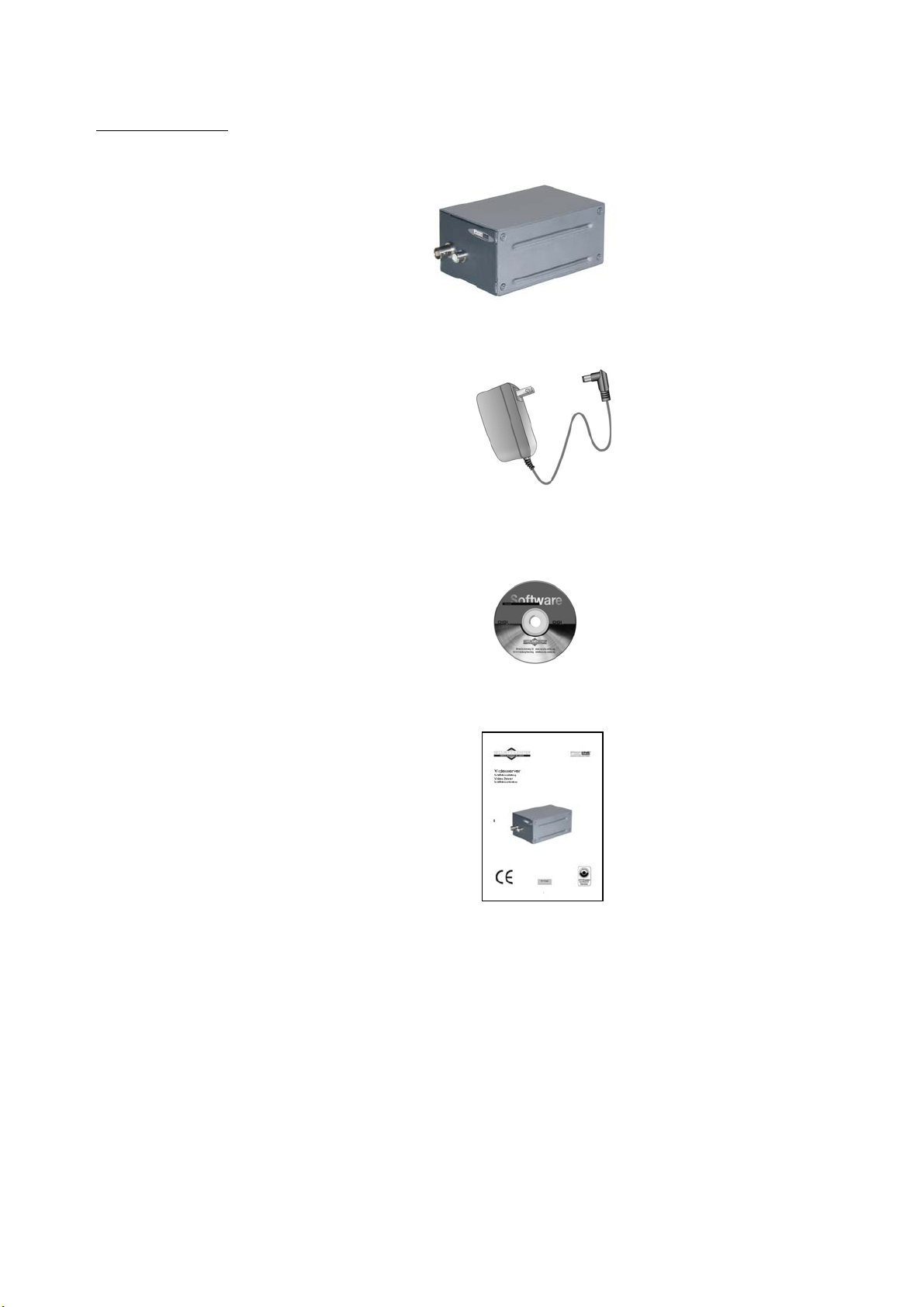
Scope of delivery
Video Server TV7202
Transformer
Software CD
Installation instructions (on CD)
5
Hardware installation
Make sure that all accessories and articles listed above are present in the scope of delivery. Depending on
application, an Ethernet cable may be required. This Ethernet cable must meet the specifications of UTP Category 5
(CAT 5) and must not be longer than 100 meters.
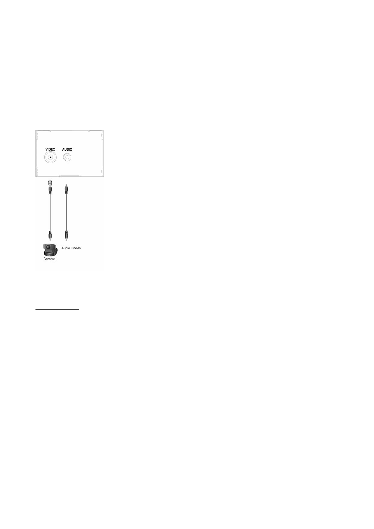
Front
BNC video input
The video port with 75-Ohm resistor is used for connecting an analogue camera. To ensure that the video
modulation mode is correctly detected, the camera must be connected and switched on before the video server is
switched on.
RCA audio input
The audio input is connected via the RCA port of the Mono-Audio-Line-In signal.
6
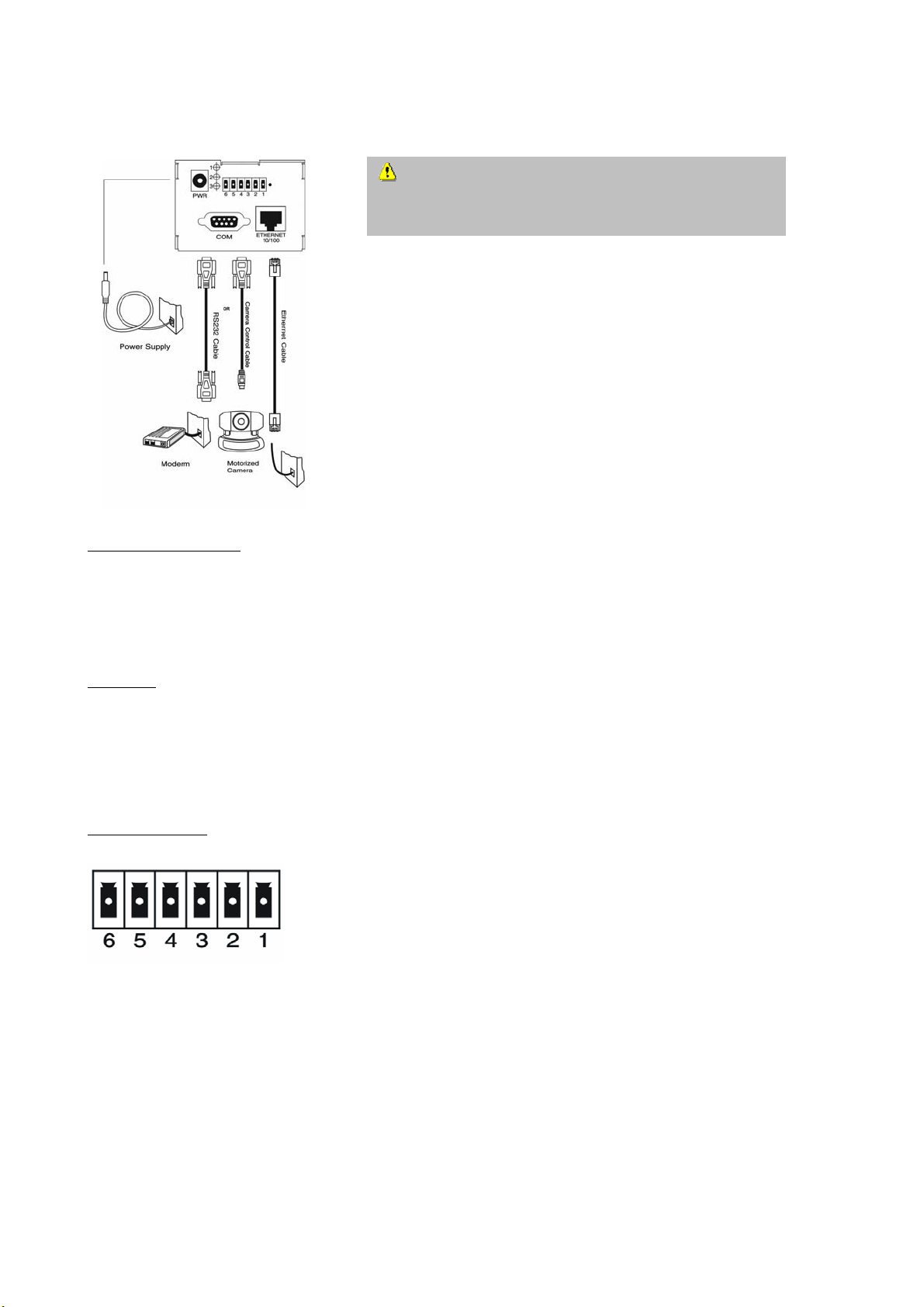
Rear
Ethernet 10/100 socket
Use a UTP category 5 (CAT 5) cable not longer than 100 meters to connect to the Ethernet. When the Ethernet
cable is correctly connected, the video server uses the Ethernet interface, regardless of any modem connection.
To prevent the risk of electric shock, first connect the
socket of the transformer to the video server before
inserting the transformer into the mains socket.
COM port
If no Ethernet is available, connect a modem cable or the null modem cable supplied to this serial RS232 port
(COM port) to be able to use the communication network. If an Ethernet connection is available, the administrator
can use this port for controlling a PTZ camera connected to the video port.
I/O terminal block
1 Å DI+ Input (max. 50mA, 12V DC)
2 Å DI- Input
3 Å SW_COMMON Output (NOC, normally open contact: switch closes on event)
4 Å SW_NOPEN Output (max. 1A, 24V DC)
5 Å RS485 - (RS485 interface)
6 Å RS485 +
7
The video server has a very flexible, general I/O interface to make it compatible with the user’s security equipment
such as sensors, alarm systems, lighting or door locks. The general I/O terminal block has 6 pins for device control.
These are divided into two categories according to their functions.
If the device connected to COM has an RS485 interface, connect two control lines to pin 5 and pin 6. After you
switch to RS485 on the configuration page, PTZ control commands are routed via pin 5 and pin 6. If the distance
to the controlled device is too great to ensure precise functioning, use an external voltage supply to amplify the
RS485 signal.
The video server has a digital input and a relay switch for device control. If you connect pin 1 and Pin 2 to an
external sensor, the status of the operating voltage is monitored according to the programmed script in the
configuration. You can switch the external device on and off with the relay switch.
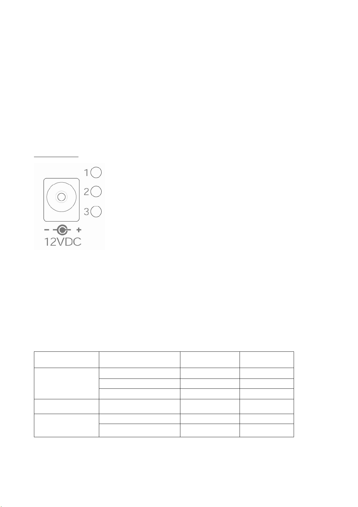
LED status display
Every time you start the video server, it runs a self-test. The self-test checks all hardware modules. When the
administrator connects the transformer both LEDs (LED 2 & 3) under the network LED flash until the self-test is run. If
any of the modules is faulty, both LEDs flash according to the pattern described in Appendix A. If the self-test is
passed, both LEDs switch off for a short time and then light according to the pattern described below. The network
interface depends on the Ethernet, modem or null modem cable peripherals. If the Ethernet connection between the
video server and the Ethernet is functioning, the video server chooses the Ethernet. If the Ethernet is not available
but a functioning modem is connected, a connection is established via the modem. If neither the Ethernet nor the
modem is available, the video server attempts to connect via the null modem.
Network interface Condition LED2 LED3
Ethernet
Before installation OFF OFF
After installation Flashing OFF
Camera control Flashing Flashing
PPP with modem After self-test Flashing ON
Before connection ON ON PPP with null modem
After connection Flashing ON
8
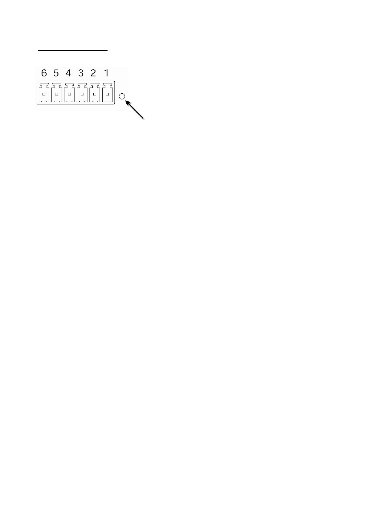
Resetting system settings
In the opening next to the I/O terminal block is a button. Press this button to reset the system or restore the factory
parameter settings. If the system cannot be not installed or is not working normally, use the pointer supplied and
follow these instructions for restoring the initial (factory) status of the system.
Insert the pointer in the hole and press the reset switch. Keeping the switch pressed, restart the system by
disconnecting and reconnecting the transformer. The system runs the self-test twice instead of the usual once, which
you can see by the flashing LEDs. After the second flashes of the LEDs, remove the pointer to release the reset
switch. The factory-set parameters are now restored.
Transformer
Connect the transformer to the voltage in socket of the video server (12V DC).
Switching on
Before installing further video servers, make a note of the serial numbers for future reference.
Before connecting up, all peripheral devices must be switched off. Use the cable supplied to connect the video
server to the peripherals as described below.
Important: Do not switch on the transformer until all other cables have been properly connected.
Make sure that all cables are correctly connected before switching on the video server. Switch on the cameras,
sensors and alarm device and then plug the transformer of the video server into the mains wall socket. If the self-test
is successful, the network speed and the video modulation mode are automatically detected. When the addressing
procedure is complete, the video server is ready to use. If the video modulation mode could not be detected, the
administrator can change the setting on the configuration page. For further information, see the section “System
configuration”.
9
First access to video server
Setting the IP address
To set the IP address of the camera:
Use a network cable to connect the video server to your computer network.
(The simplest way is to connect the video server direct to your PC using a cross-link cable.)
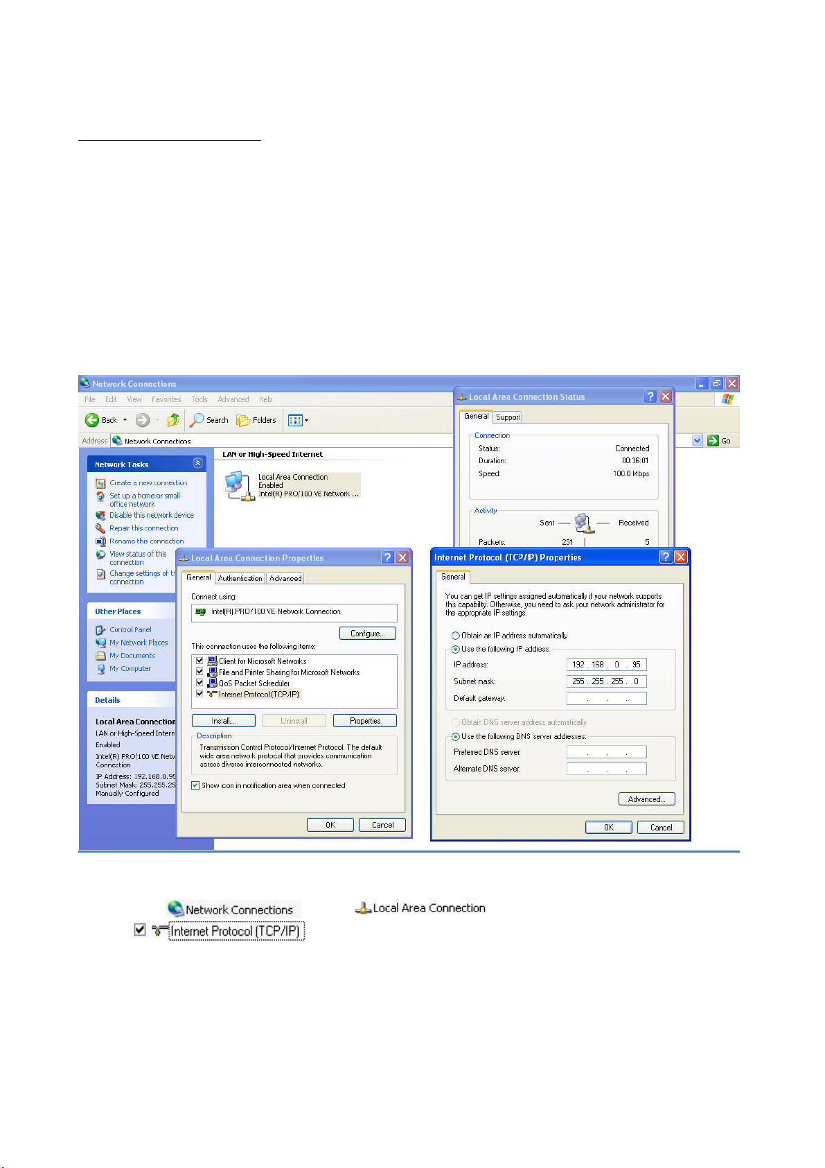
If your PC is not yet integrated into a network, you first have to configure it for the network application. Do this by
opening the Properties page for your network.
(This also applies if the camera is connected to the PC via a hub or switch.)
1. Click
2. Enter a fixed IP address and subnet mask
(e.g., 192.168.0.95 and as subnet mask 255.255.255.0).
- The network connection of your PC is now configured.
, select and open the Properties page of the
.
10
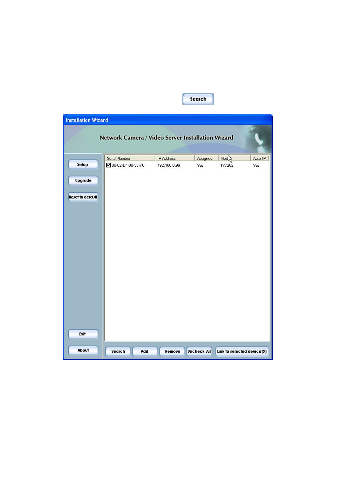
Now start the Installation Wizard from the software CD supplied.
3. Follow the installation instructions of the Installation Wizard.
4. If installation is successful, start the program under Programs/Installation Wizard.
5. Following the program start, the Installation Wizard automatically searches for a connected video server.
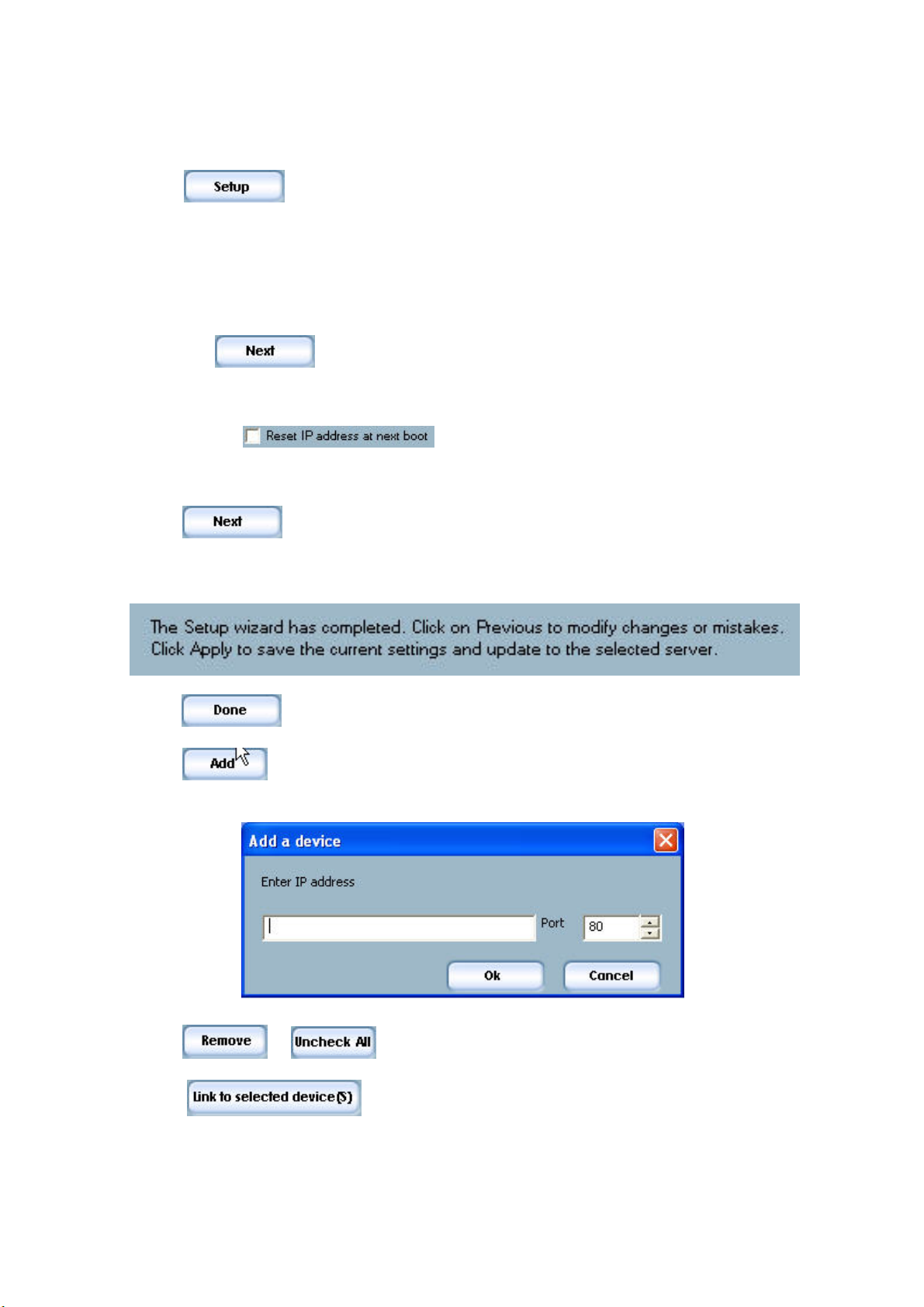
6. If no video server is found in the first search, click
Note: If no video server is found via the manual search, change the network settings of your PC as described
in the instructions.
for a new search.
11
7. Select one of the video servers found.
8. Click
to enter video server setup mode. You are prompted to enter the administrator
password (Server Root Password). For the first access to the video server, use the device serial
number as the password. This is printed on the bottom of the video server (observe uppercase
and lowercase!). You can change the hostname (e.g., videoserver) the administrator password and the
date/time settings of the video server. If you cannot access the settings, check the IP addresses of
your network adapter and your video server. The IP addresses must be in the same subnet area. If
necessary, change the IP address of the network adapter (page 7).
9. Now click
to change the IP address or the subnet mask of the video server or network
environment. If you use a router in your network, enter this IP address (gateway) in the “Default
Router” field.
10. If you disable
, you do not have to reassign the IP address of this video
serve following a power failure. Otherwise, you have to reassign the IP address after every video server
restart.
11. Click
.
12. Follow the instructions on the screen to save or change your settings.
Click
13. Click
only if the video server was not found by the automatic search.
14. Click
15. Click
Explorer.
.
to add a video server direct via the IP address or its domain name. You need this
or to remove one or all network video servers from the menu.
to set up a link to the selected video server via the Internet
12
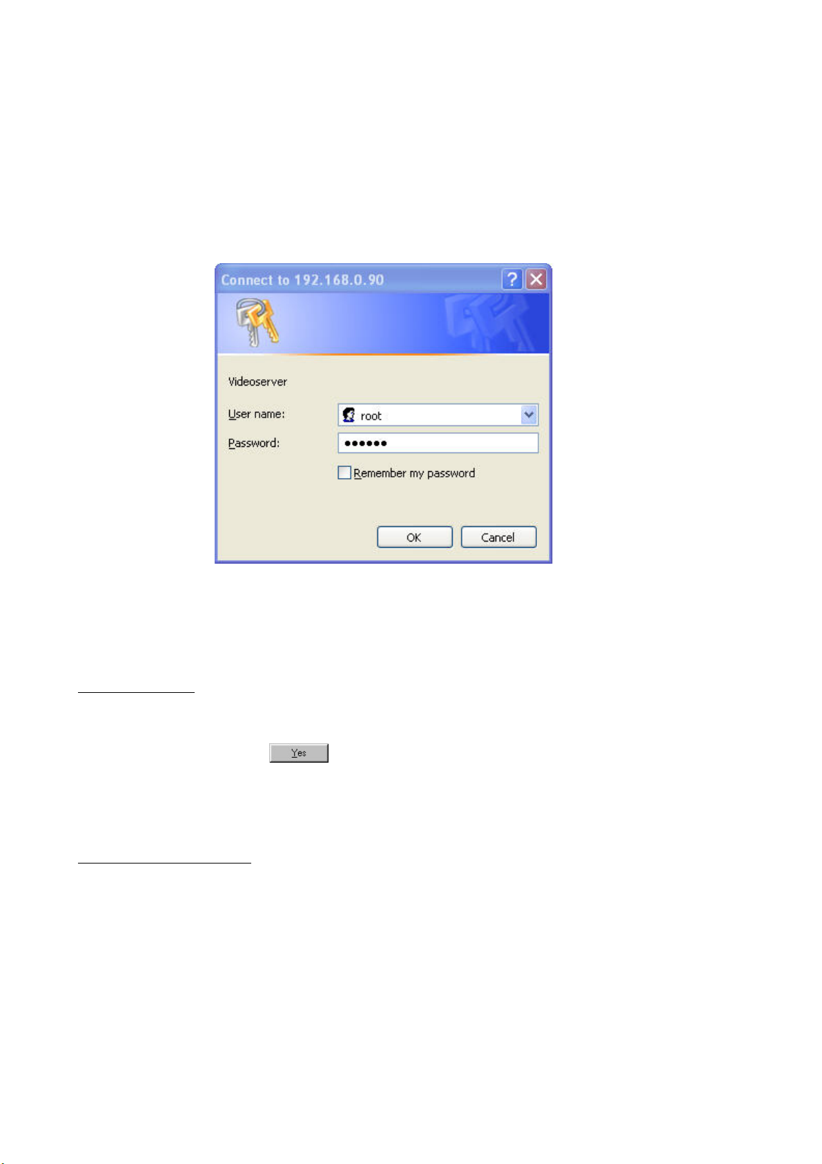
Access to the video server via the Internet Explorer
After starting the web browser and entering the URL of the video server (http://<IP address of video server>), enter
your user name and password in the login dialog box. The first time the administrator uses the video server,
he/she has to enter the user name root and the serial number as password (with no spaces and letters in
uppercase). If you changed the password in the Installation Wizard, use the new password. The serial number is
printed on the bottom of the video server casing. Primary users have access as soon as the administrator has
created and added the user profiles.
You are now connected with the video server and can see a video stream.
Note: Your PC’s security settings may prevent a video stream. You can change the security settings to a lower level
under To ol s /Internet Options/Security. Make sure you enable Active X Control Elements and Downloads.
Installing the plug-in
When you first access the video server under Windows, the web browser may ask for the installation of a new plugin for the security network camera. This plug-in was registered at certification and is used to display video pictures in
the browser. To continue, click
. If the web browser prevents continuation of the installation, open the
Internet security option and reduce the security level or consult your administrator.
Primary user privileges
Main screen with camera view
In the top left corner is a logo. This represents a link to other websites or resources, depending on the settings in the
configuration. The assigned subtitle and the system date and time are displayed on the banner over the window.
Click Configuration on the right of the window to open the configuration page.
13
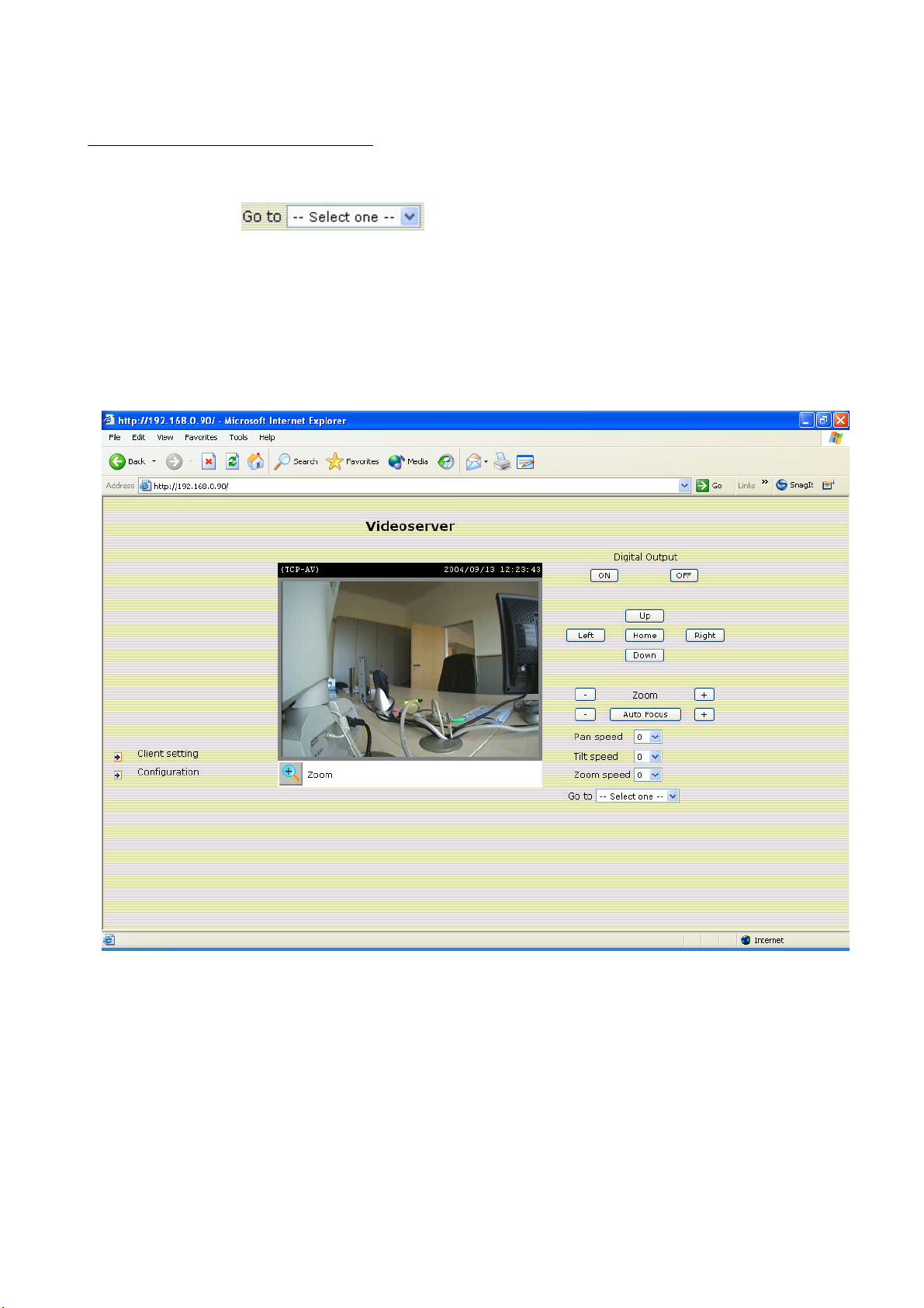
PTZ camera control (Pan/Tilt/Zoom camera)
A motor-driven PTZ camera first has to be configured in advance. Using the controls on the right of the video, you
can control the motor-driven camera connected with the video server. Open the list of preset positions to select the
camera, and then click
with camera control privileges can only view the preset locations. With the five buttons on the right of the picture,
the cameras can be controlled with other functions apart from pan, tilt and zoom. These should be preconfigured
by the administrator with the aid of the camera instructions.
If the PTZ camera is installed on the video server, you can click any position on the screen to move the camera to
this position. Currently, the video server supports Sony EVID30, Canon VCC4 and Pelco-D PTZ cameras for
this operation.
<url> http://<video server>
<video server> is the hostname or IP address of the video server.
. Only the administrator can preset the camera locations. Users
14
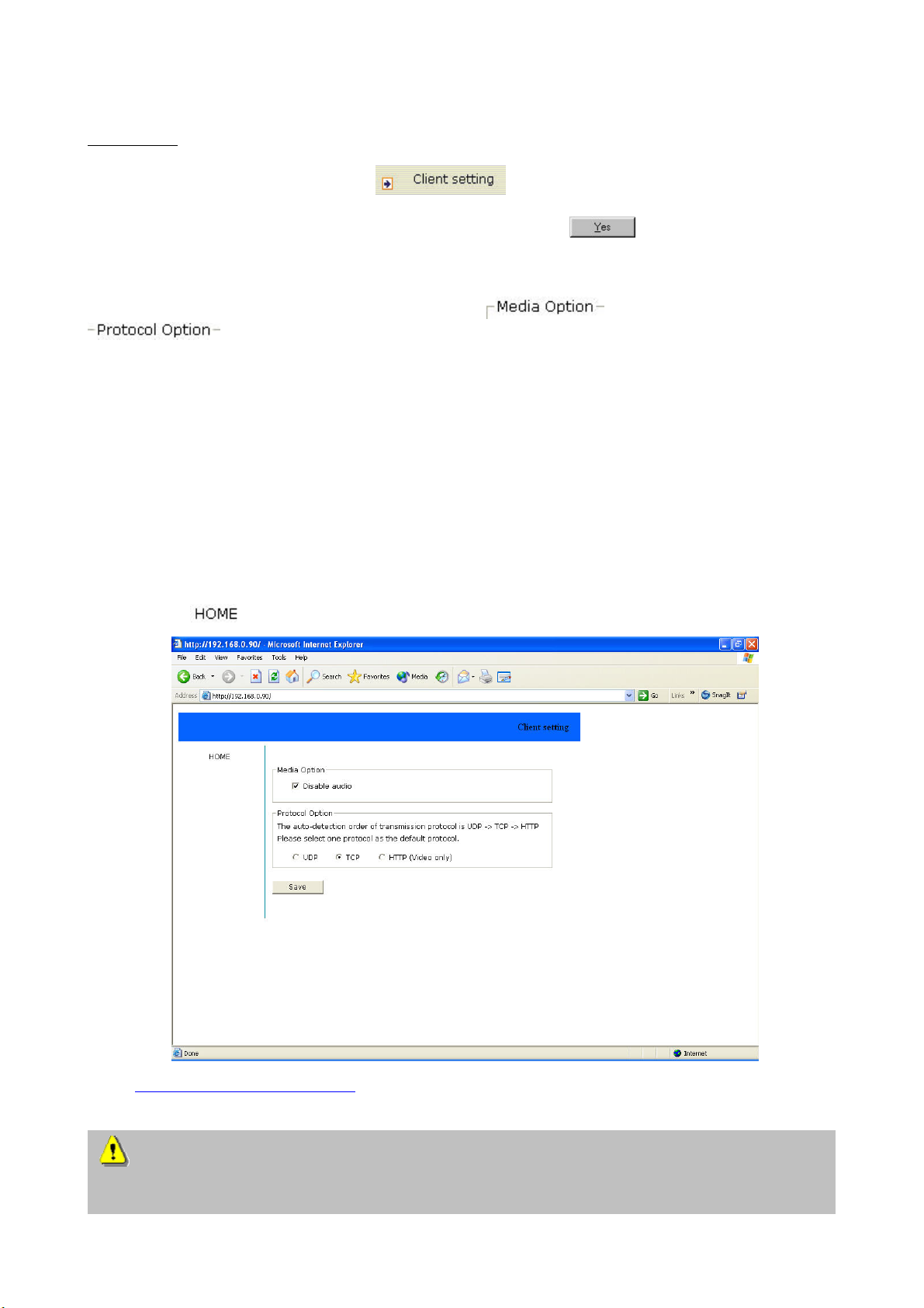
Client settings
When you first access the page with the
button under Windows, the web browser asks
for the installation of a new plug-in. This plug-in was registered at certification and can be used to change
parameters on the Client settings page. To install the plug-in, click
. If the web browser prevents
continuation of the installation, open the Internet security option and reduce the security level or consult your
administrator.
On the Client setting page, two settings are available,
for disabling audio output, and
for selecting the transmission protocol between the client and server. Three protocols are
provided for optimising the application: UDP, TCP and HTTP.
The UDP protocol gives you more realtime audio and video streams. However, some data packets can be
lost due to the large data volume in the network and pictures can be unclear.
With the TCP protocol, fewer data packets are lost and the video display is more accurate. The
disadvantage of this protocol is that the realtime stream is worse than with the UDP protocol.
Use the HTTP protocol if the network is protected by a firewall and only the HTTP port (80) is to be
opened. In this mode, no audio is transmitted with the video pictures. The UDP protocol is recommended if you
have no special requirements. The client is selected in this order: UDP / TCP / HTTP. When the security network
camera has been successfully connected, the Protocol Option box shows the selected protocol. The selected
protocol is registered in your PC and used for the next connection. After changing the network environment or
if you want to make a new search using the web browser, select the UDP protocol manually, save it and
then return to
to set up the connection again.
<url>
http://<Video Server>/client.html
<video server> is the domain name or the original IP address of the video server.
If you use a modem for the connection, the video server sends video data only (no audio), since the low
bandwidth does not meet the requirements for video and audio. On the Client settings page, the protocol
option is set to Http protocol.
15
System configuration
Two methods are available for configuration. The web interface offers a simple and clear application option,
whereas the FTP with the script file is suitable for mass installation. Access to system configuration is reserved for the
administrator only. The administrator can enter the URL in the figure below to jump direct to the configuration page.
If (as administrator) you want to set options via the URL, refer to the section about the extended application.
<url>
<video server> is the domain name or the original IP address of the video server.
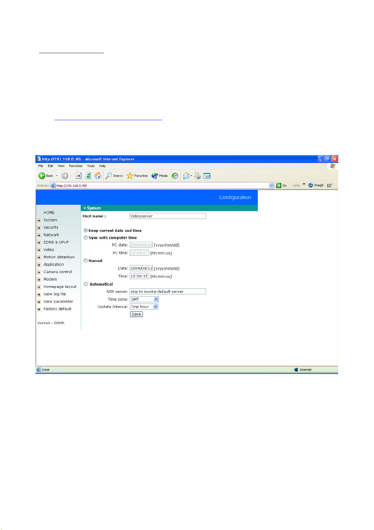
System
To change the system name, enter a name under Host name. This name then appears at the top of the main
page. To change only the hostname without changing the date and time of the video server, click Keep current
date and time.
There are three ways of setting the system date and time. The simplest way is to click Sync with computer time.
Or you can click Manual to set the date and time manually. Note the date/time format when entering in the
respective fields. Otherwise, click Automatical, which synchronises the video server with the time servers via the
Internet. This can fail if the associated NTP server cannot be reached or is located in a local network. If you leave
the NTP server field blank, the video server connects to the default time servers. If specific time servers have been
assigned, enter them here. The format of the domain name or the IP address is valid as long as the DNS server is
available. Don’t forget to set the correct Time zone for the local settings. This influences only the hour display in
the NTP method. If you enable Automatical, the video server occasionally synchronises with the NTP server. You
can set the time synchronisation interval to the hour, day, week or month under Update Interval.
http://<Video Server>/setup/config.html
16
Click
to enable your changes to take effect.
The server rejects an invalid date/time entered by the user and returns to the previous setting.
Valid years are between 2000 and 2035.
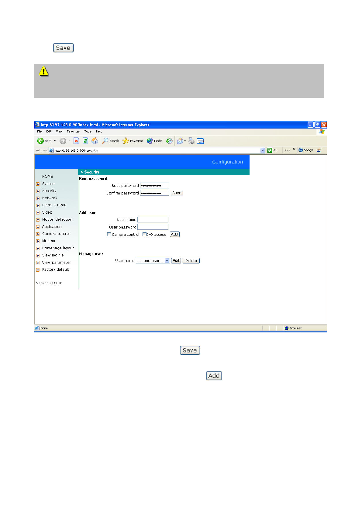
Security
To change the administrator password, enter the new password in both text boxes. For security reasons, the
password entered is represented by asterisks. After
is clicked, the web browser prompts the
administrator to enter the new password for accessing the equipment.
To add a new user, enter the user name and password and click
to confirm you input. Up to twenty user
accounts can be defined. Since only the administrator can change the user password, it is not necessary to confirm
the user password. The privileges of the user for I/O access and camera control can also be set by enabling the
corresponding boxes. The way the operation field is displayed on the main page depends on how you set the user
privileges.
17
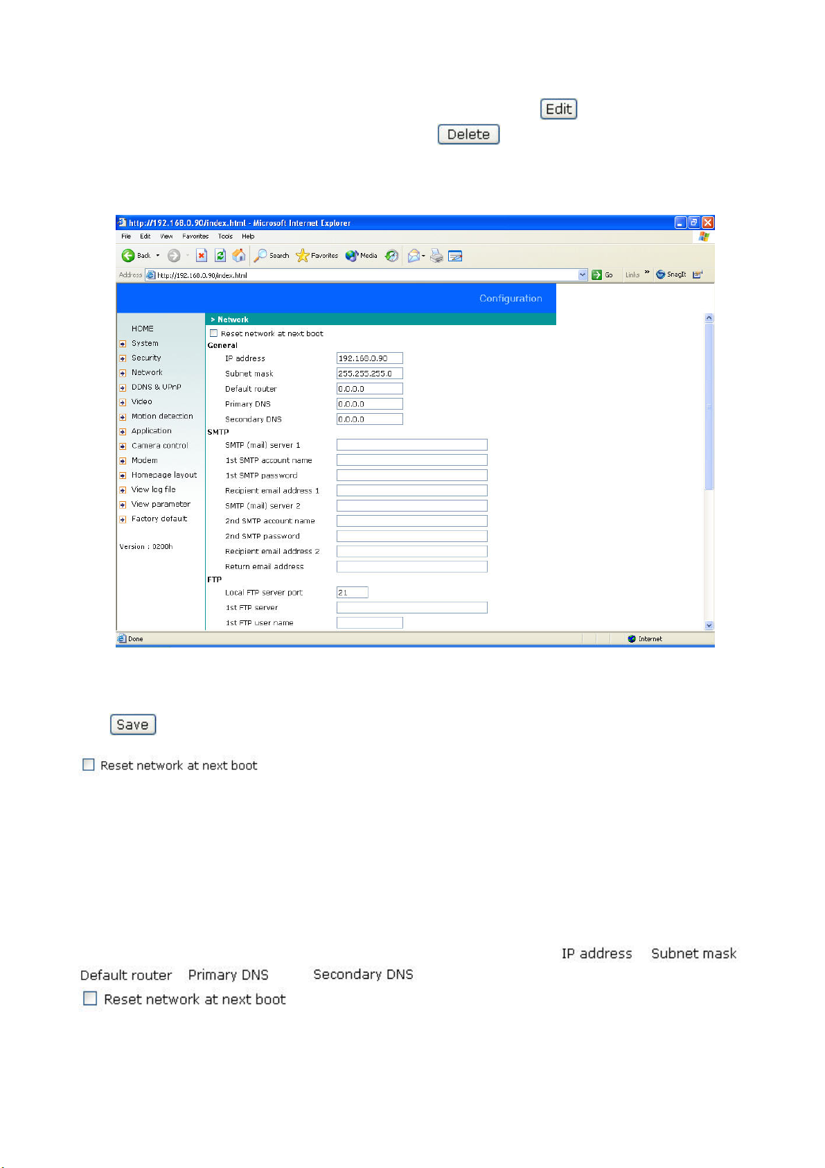
To edit a user account, first open the list of users. Select a user name and click
.
To delete a user, open the list of users and select a user. Click
to delete.
Network
The system is rebooted to make your changes effective. Make sure that each field is correctly filled before you
click
.
The default status is checked to prevent incorrect input during installation. This can
take a long time for the software installation at every reboot of the video server. For this reason, you should disable
this option after entering the network settings correctly (especially the IP address). If this option is disabled, the video
server is started with the current IP address. Following a power failure, the video server can be automatically
restarted and operated. The user can start the IP installation program to check the IP address assigned to the video
server if this address was forgotten or if the UPnP function is used by the video server (under MS Windows XP, the
UPnP function is offered under Network Location).
The administrator can change the network settings to adapt them to the networks used. Some of the subnet masks
with wideband service may be different from the default parameter 255.255.255.0 and the service provider may
assign his own specific network settings. The administrator should change the configuration according to the
parameters supplied by the service provider. The configuration can include
, ,
, and . After changing the network settings, leave the option
blank to skip the installation procedure when the system is rebooted, since
otherwise the settings are deleted.
18
 Loading...