

Page 1
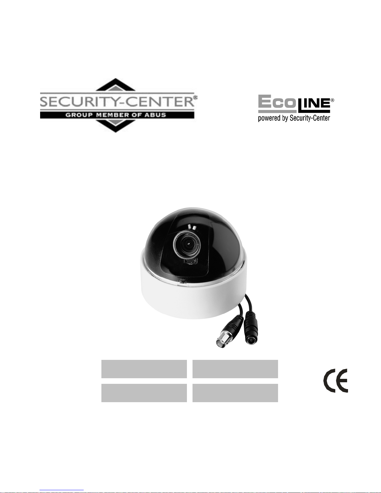
Video surveillance camera
Installation Guide
TV7014 TV7015
TV7016 TV7017
1
Page 2

1. Preface
Dear Customer,
Thank you for purchasing this ECOLINE digital surveillance camera.
You made the right decision in choosing this state-of-the-art technology. This
product complies with the current standards of domestic and European
regulations. The CE has been proven and all related certifications are available
from the manufacturer upon request. To maintain this status and to guarantee
safe operation, it is your obligation to observe these operating instructions!
The ECOLINE mid-size dome camera is equipped with a 3.5-8 mm DC variable
focus lens with a 1/3” SONY Super HAD interline transfer CCD image sensor.
The all state circuitry provides extremely long life and a high level of reliability.
These cameras use first class microelements that are resistant to external
electromagnetic fields. They offer cutting-edge technology for advanced video
surveillance.
2
Page 3

2. Scope of delivery
ECOLINE mid-size dome camera (model as described)
Installation instructions
Fastening screws
3. Features
All mid-size dome cameras of the ECOLINE series have the following functions:
a) Auto electronic shutter (AES)
b) Auto gain control (AGC)
c) Backlight compensation (BLC)
Additional for colour cameras of this series:
d) Auto white balance (AWB)
e) Digital signal processing (DSP)
f) Flicker compensation (FK)
4. Precautions
To reduce the risk of electric shock, do not remove cover (or back) – there are
no user serviceable parts inside. Refer servicing to qualified service personnel.
Do not expose the camera to rain or moisture or try to operate in
wet areas. This camera is designed for indoor use only. If the camera
becomes wet, turn the power off immediately and ask a qualified service
technician to check it before turning the power on again.
Never point the camera towards the sun. Whether the camera is in use
or not, never aim the CCD at the sun or other very bright objects (laser light).
3
Page 4

This can damage the CCD element and create white dots on the monitor, a sign
that CCD pixels are destroyed.
Operate the camera only within the specified temperature,
humidity and power ranges. Operating the camera outside the prescribed
ranges can lead to reduced product life and early malfunction. Greatly
exceeding the specified operating ranges can also result in immediate failure of
the camera. All specifications can be found in the technical data. Observe the
correct camera model.
Handle the camera with care. Do not abuse the camera. Avoid striking,
shaking, etc. Mount the camera in a shake-free area. The camera could be
damaged by improper handling, storage or transport.
4
Page 5

5. Installation instructions
This camera is designed for indoor use only. If the camera is used outdoors,
damage may occur as a result of dampness and temperatures outside the
prescribed range. The ECOLINE colour cameras are equipped with an IR cut
and cannot be used in combination with IR illumination.
Perfect (colour) video pictures depend a great deal on the illumination. Please
take this into account when installing artificial light sources. Light sources with a
colour temperature different from daylight may effect colour drifts for colour
cameras.
The cause of bad picture quality goes hand in hand with improper cabling.
Ensure professional installation and avoid passive video distributors. Always
select the shortest distance between the camera and the video unit.
Before installing a video surveillance system with camouflaged cameras, please
be aware of any possible legal regulations that may apply.
5
Page 6
6. Description of the camera
6
Page 7
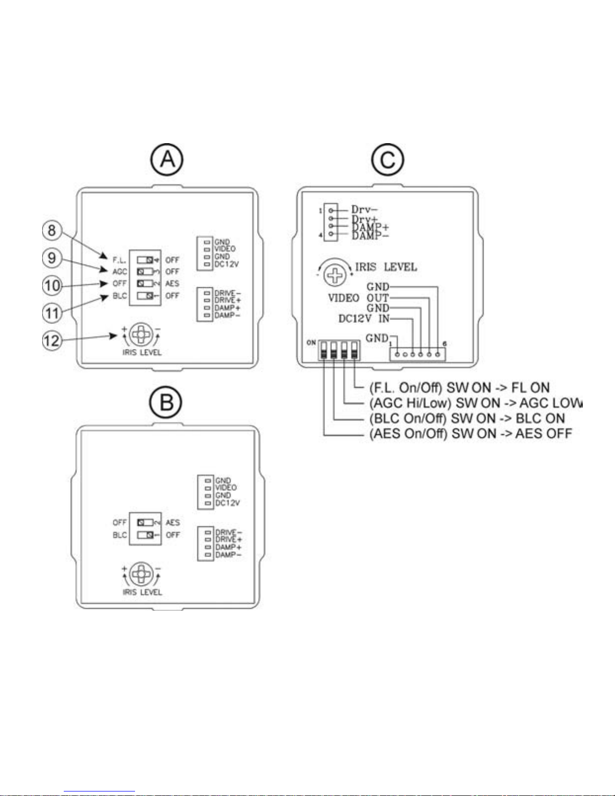
(A) Colour camera
291,000 pixel
(B) Colour camera
438,000 Pixel
(C) B&W camera
291,000 / 438,000 pixel
7
Page 8

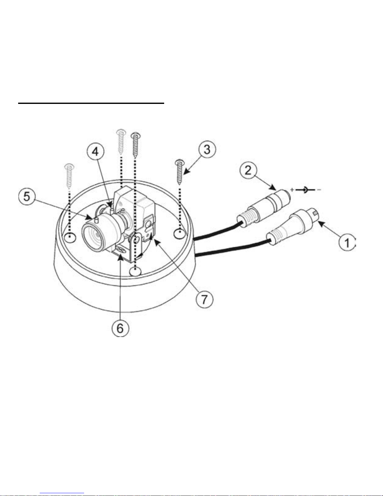
(1) Video output connector (VIDEO OUT)
BNC output. This connector is for connecting the camera video signal to the
VIDEO IN connector of, for example, the monitor (composite signal: 1Vp-p).
(2) Power input
12V DC voltage. Approved for DC voltage are class 2 power supply units only.
Ensure the polarity is correct.
(8) Selector for flicker compensation (FL)
- adjustable for colour cameras
This function compensates image flickering occurring with 100Hz fluorescent
lamps. As a rule this function is not necessary for the European market. The
switch should therefore be positioned to OFF.
(9) Selector for automatic gain control (AGC)
- adjustable for colour cameras
Select the desired mode.
AGC high (OFF position): The image is maximally amplified (approx. 26 dB).
Noise may appear in the image. Suitable for low illumination.
AGC low (ON position): Normal amplification of the image (approx. 16 dB).
Suitable for sufficient illumination.
8
Page 9

(10) Automatic / electronic illumination selector (AES)
The ECOLINE mid-dome camera is equipped with a DC controlled auto-iris lens
(automatic illumination control by the lens). Please do not change the factory
setting (OFF).
(11) Backlight compensation mode selector (BLC)
Depending on the lighting conditions, select one of the following.
BLC ON: The centre of the screen is brighter than the edges of the screen.
Select this mode if the background light is as strong as a spotlight.
BLC OFF: Select this mode if the main object is not located in the centre of the
screen and a source of bright light is located near the centre of the screen.
9
Page 10

7. Installation
Proceed as follows when installing the camera.
1. Select a suitable place on the ceiling of the room where you would like to
mount the camera.
2. Connect the video cable (recommended cable type: RG58) to the BNC
video out (1) of the camera and to the following connected video unit. The
maximum cable length should not exceed 200 m.
3. Connect a 12V DC power supply to the power input of the camera (2).
4. Hold the camera at the location where you want to mount it. Check the
orientation and angle of the camera.
5. Remove the plastic dome from the housing by carefully unscrewing it
counter-clockwise.
6. Change the orientation of the camera module (7) if necessary by loosening
the fixing screws (6), modifying the inclination and direction of the camera
module, and then tightening the fixing screws.
7. Select the desired image framing at the lens by setting the zoom (5).
Optimise the sharpness by adjusting the focus (4) at the lens.
10
Page 11

8. If it is necessary, you can manually change the opening of the power-
regulated auto-iris aperture using the regulator (12) on the camera
module.
9. If there is a video picture visible on the monitor, adjust focus and
zoom as required. If there is no video picture on the monitor, please
check the following.
• Is the monitor switched on and is the level of contrast and brightness
set correctly?
• Is the video cable between the camera and monitor connected
properly (also check the resistor settings)?
• Has the auto-iris connector of the lens been inadvertently
disconnected?
• Is the regulator (12) for the auto-iris lens correctly set?
• Is the illumination where the camera is located sufficient for this
camera model?
10. Fasten the dome camera to the desired mounting location using the
supplied screws (3) and screw on the plastic housing again.
11
Page 12
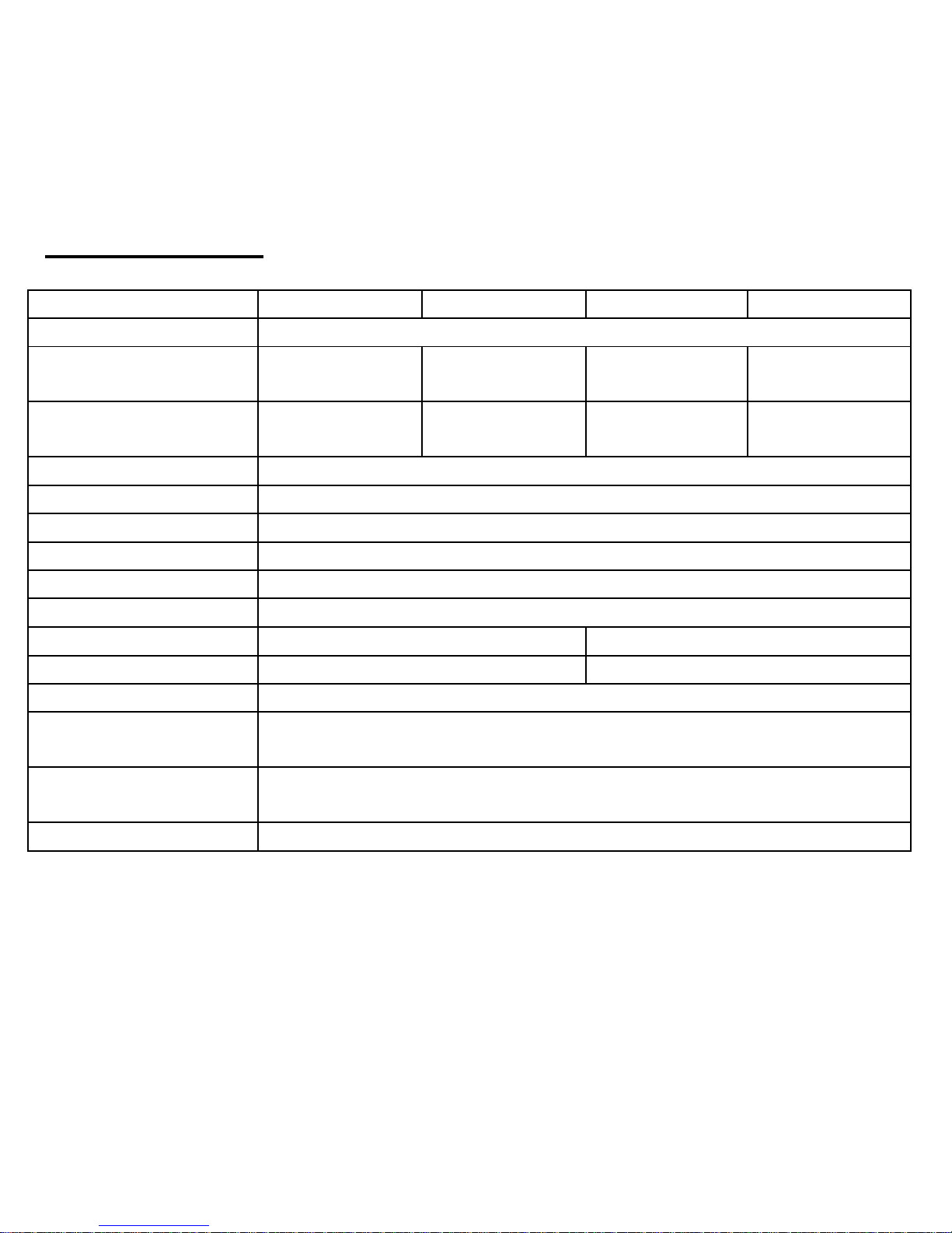
8. Technical data
Model number TV7014 TV7015 TV7016 TV7017
Image sensor 1/3” SONY Super HAD CCD
TV lines / pixels 420 /
291,000
600 /
438,000
380 /
291,000
470 /
438,000
Minimum
illumination (IRE 30)
0.065 lux
(F1.6)
0.13 lux
(F1.6)
0.13 lux
(F1.6)
0,26 lux
(F1.6)
Signal-to-noise ratio > 48 dB
AES 1/50s – 1 / 110,000s
Lens 1/3” / 3.5 – 8 mm / F1.6 / DC auto-iris
Horizontal angle 35°-78°
Video out 1Vp-p / 75 Ohm / BNC connector
Power source 12V DC
Power consumption 1.32W 2.64W
Video norm CCIR PAL
Dimensions / Weight Ø107 x 91 mm / 250 g
Ambient operating
temperature
-10°C – +50°C
Ambient operating
humidity
max. 90% / non-condensed
Protection type IP 54
12
 Loading...