

Page 1

1
O P E R A T I N G I N S T R U C T I O N S
Radio alarm equipment SECVEST 868
OPERATING INSTRUCTIONS
Perfect security for apartment, home
and office
These operating instructions are an important product
accessory. They contain important installation and operation
information. Bear this in mind if you pass the product on to
others. Store these instructions in a safe place for future
reference.
For a list of contents with page numbers, see page 3.
Inv. 11772594
Page 2

2
0. Introduction
Dear Customer,
Thank you for purchasing the SECVEST 868 radio alarm panel. You
made the right decision in choosing this state-of-the-art technology,
which complies with the current standards of domestic and European
regulations. The CE has been proven and all related certifications are
available from the manufacturer upon request.
To maintain this status and to guarantee safe operation, it is your
obligation to observe these installation instructions.
In the event of questions, please contact your local specialist dealer.
© Security-Center GmbH & Co. KG, June 2007
Every effort has been made to ensure that the contents of this manual
are correct. However, neither the authors nor Security-Center GmbH &
Co. KG accept any liability for loss or damage caused or alleged to be
caused directly or indirectly by this manual. The contents of this manual
are subject to change without notice.
1. Usage in accordance with regulations
This radio alarm panel is used in combination with the detectors and
signalling devices for protecting your property. You can use it to
protect your company, house, garage, garden house, weekend
cottage, etc.
The alarm system registers unauthorised break-ins by switching output
contacts to which you can connect visual, acoustic or silent alarm
transmitters.
The alarm contacts and connected components must be kept free of
moisture (bathrooms and similar surroundings are to be strictly avoided).
Use of this product for other than the described purpose may lead to
damage of the product.
Other hazards such as short-circuiting, fire, electric shock, etc., are also
possible. The power unit is designed for operation with mains electricity
at 230 Volt AC / 50 Hz.
No part of the product may be changed or modified in any way.
Connection to the public power network is subject to country-specific
regulations. Please be aware of applicable regulations in advance.
Page 3

3
2. Contents
0. Introduction.................................................................................................... 2
1. Usage in accordance with regulations .................................................... 2
2. Contents ......................................................................................................... 3
3. Precautions .................................................................................................... 4
4. Overview of panel and keypad ................................................................ 5
5. Graphic display ............................................................................................. 6
6. Activating the radio alarm system ............................................................ 7
6.1. Quick activation .................................................................................... 7
6.2. User code................................................................................................ 7
6.3. Telecommand ....................................................................................... 7
6.4. Proximity tag........................................................................................... 7
6.5. Radio cylinder ........................................................................................ 7
7. During the delay period .............................................................................. 8
8. Unsuccessful activation ............................................................................... 8
8.1. The delay time was not started .......................................................... 8
8.2. Important differences when setting the panel with force set
functions (force omit set) ............................................................................ 9
8.2.1. Automatic omit (force set) with acknowledgement ............. 9
8.2.2. Automatic omit (force set) without acknowledgement ....... 9
8.3. The delay time was started ............................................................... 10
9. Following successful activation ................................................................ 11
9.1. Acknowledgement tone on alarm panel ......................................11
9.2. Acknowledgement tone on info module ...................................... 11
9.3. SMS message .......................................................................................11
9.4. Acknowledgement on siren.............................................................. 11
9.5. Universal module ................................................................................. 11
10. Deactivating the radio alarm system ................................................... 12
10.1. User code............................................................................................ 12
10.2. Telecommand ................................................................................... 12
10.3. Proximity tag....................................................................................... 12
10.4. Radio cylinder .................................................................................... 12
11. Activating partitions ................................................................................. 13
11.1. On the panel......................................................................................13
11.2. Using radio remote control..............................................................13
12. Internal activation .................................................................................... 14
12.1. On the panel......................................................................................14
12.2. Using radio remote control ..............................................................14
13. In case of alarm.........................................................................................15
13.1. Local/Internal alarm .........................................................................15
13.2. External alarm ....................................................................................15
13.3. Silent alarm .........................................................................................15
14. Resetting an alarm....................................................................................16
15. Alarm transmission by telephone ...........................................................17
16. Remote Control by Phone ......................................................................17
17. User menu...................................................................................................18
18. Settings in the user menu.........................................................................19
18.1. First steps in the user menu ..............................................................19
18.2. List of menu items in user menu ......................................................19
18.3. Recording voice messages .............................................................20
18.4. Omit zones ..........................................................................................21
18.5. Install user ............................................................................................21
18.5.1. Edit user........................................................................................22
18.5.2. Add new user .............................................................................26
18.5.3. Delete user ..................................................................................26
18.6. View log...............................................................................................27
18.7. Additional functions ..........................................................................29
18.8. Test........................................................................................................30
18.9. System configuration ........................................................................31
18.10. Follow me..........................................................................................33
18.11. Exits on/off.........................................................................................33
18.12. Telephone call .................................................................................34
19. Error display ................................................................................................34
19.1. Errors, meaning, causes and suggested solutions....................... 35
20. Declaration of Confirmity ........................................................................37
21. Operating Mode Overview..................................................................... 37
Page 4

4
3. Precautions
!WARNING!
To avoid fire and injury, please observe the
following:
• Securely fasten the device at a dry
location in the building.
• Ensure sufficient air circulation for the alarm
panel.
• Do not expose the device to temperatures
less than 0°C or more than 50°C.
• The device is designed for indoor use only.
• Humidity must not exceed 90% (non-
condensed).
• Make sure that no metal objects can be
pushed into the equipment from outside.
• Ensure that the voltage is disconnected
when performing work on the device.
!IMPORTANT!
Please observe the following regulations to
ensure trouble-free operation of your
system.
• The alarm panel is supplied with DC power
by means of the internal transformer.
• The transformer is connected to the 230V
AC building mains by means of a separate,
electrically protected line.
• Connection work to the building mains is
subject to country-specific regulations.
• An internal rechargeable battery supplies
emergency standby power.
• Always replace fuses with fuses of the
same rating, never higher.
!IMPORTANT INFO!
Burglar alarm centres in general:
If the equipment is not correctly installed,
signals may be misinterpreted and result in
false alarms. The costs resulting from the
deployment of rescue organisations, e.g.: fire
or police, are borne by the operator of the
equipment. Therefore please read the
instructions very carefully and follow the
installation instructions for lines and
components precisely.
Page 5

5
4. Overview of panel and keypad
Integrated siren
and loudspeaker
Button for
deactivating radio
alarm panel
Control buttons
Keypad alarm keys
for panic, fire,
medical and social
Integrated
microphone
Graphic display
multiline display
Read area of
proximity tag.
Button for
activating radio
Keypad for
programming
and operating
Keypad cover
Page 6

6
5. Graphic display
The graphic display informs you about all events concerning the radio alarm system. The following is a summary of the different display messages and
their meaning:
This symbol appears when the
activity monitoring is active. Make sure
you also define the period
of monitoring. Activity monitoring
also works when the radio alarm system
is deactivated.
This symbol appears if a voice message
exists that you should listen to. An
acoustic message is issued every time
you deactivate the radio alarm panel.
This is: „There ia a message waiting“
Menu
MenuMenu
Menu
Press the button under the menu display.
The alarm panel asks you to enter your
access code (user code). If the code is
accepted, you see the user menu. Here
you can perform all user functions
released for the installer. Note that some
functions in the user menu require a user
code with administrator rights (master
code).
The four black bars stand for the
four individual partitions of the
Secvest 868. A letter in the black
bar represents the state of the
partition (1–4). The letters and
their meaning:
U:
U:U:
U:
Deactivated
S:
S:S:
S:
Activated
P:
P:P:
P:
Internally activated
Note: A letter is displayed in a bar
only if at least one detector is
present in this partition.
This symbol indicates an error that
must be cleared immediately. For
a summary of the different error
displays and their meaning, see
the table at the end of these
instructions. To display the error,
press the button under the
display.
You are prompted to enter a
valid user code.
21:00
21:0021:00
21:00
01/08/2007
01/08/200701/08/2007
01/08/2007
Displays the current time and date.
Page 7

7
6. Activating the radio alarm system
You can activate the radio alarm system in different ways. The panel gives acoustic messages. Depending on whether a partition or the complete
system has been activated, this message is either “The partition is setting” or “The system is setting”
6.1. Quick activation
Note that this function can
be deactivated to prevent
unauthorised operation of
the equipment. This
function is located in the
Installer menu under System
Options \ User access \
Quick set.
To activate the complete
radio alarm system, just
press the quick set key as
shown.
6.2. User code
If the quick set function is
deactivated, you have to
enter a user code to
activate the equipment. If
the panel has only one
area, just enter your user
code. The area for which
this user code is valid is now
activated. If your user code
is valid for two or more
areas, you now receive a
selection of areas to
activate. Read the sections
“Activating partitions” and
“Part set” (p. 12/13).
6.3. Telecommand
With a telecommand, you
can activate the complete
radio alarm system by
pressing the “fully set”
button. The other buttons
on the telecommand are
for activating a partition or
to activate the radio alarm
system internally. Read the
sections “Activating
partitions” and “Part set”
(p. 12/13).
Do you have zones with the
attribute Force Arm Set, it
may be necessary to
confirm the activation by
pressing the full set button
again.
6.4. Proximity tag
You can use the proximity
tag to fully
activate/deactivate the
radio alarm system or a
partition. The proximity tag
is used instead of the entry
of a user code. If you have
a proximity tag and the
authorisation to activate
two or more partitions, you
have to decide which
partition you want to
activate after holding the
proximity tag in front of the
system. Read the sections
“Activating partitions” and
“Part set” (p. 12/13).
6.5. Radio cylinder
You can also use the radio
cylinder to fully activate
the system or a partition. To
activate the radio alarm
panel, first press the button
on the cylinder and then
lock the door. After you
lock the door, the alarm
system is activated.
Page 8
8
7. During the delay period
If no errors occur that prevent activation (zone open), the radio alarm system starts the configured exit delay period. The panel gives acoustic
messages. Depending on whether a partition or the complete system has been activated, this message is either “The partition is setting” or “The system
is setting”. During this period, you must leave the premises.
A continuous tone sounds during the delay period. This tone is also emitted by the info module (if fitted).
Some zones can be open during activation and during the exit delay period (entry/exit, entry to follow). However, these zones must be closed before
the delay period expires – otherwise, there is a local alarm.
When entry/exit or entry to follow zones are open, a pulsed tone is emitted during the exit delay period until all zones are closed.
8. Unsuccessful activation
There are two different situations here:
a) The delay time was not started.
b) The delay time was started.
8.1. The delay time was not started
The system does not start the delay time due to a system error.
If you try to activate the system with the following:
• Fast activation
• Telecommand
• Radio keypad
• Radio cylinder
You see the following graphic display:
At the same time an acoustic warning is issued.
This is: “The system cannot set“
Please enter a valid user (access) code and go on as described on the
next column.
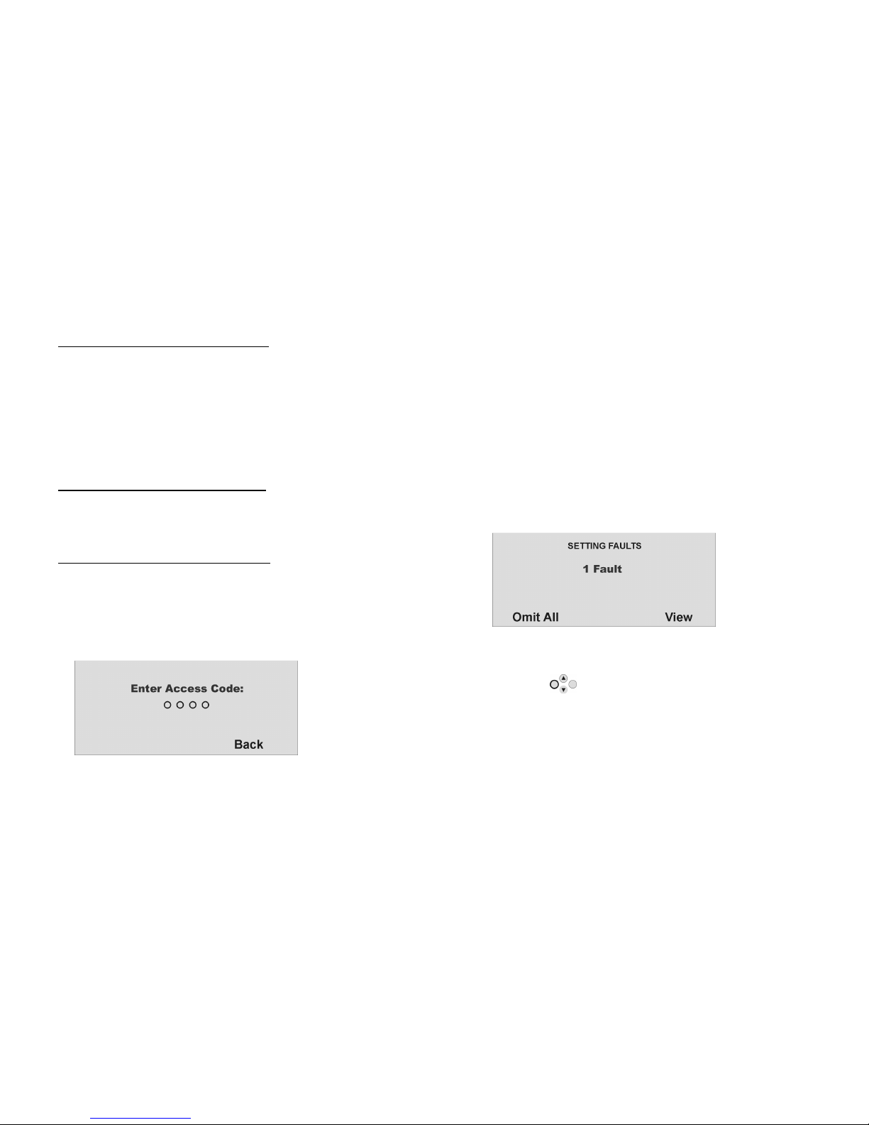
If you try to activate the system with the following:
• User code
• Proximity key
The display shows the current error. You see the following graphic
display:
Select “Omit All” to remove the zone(s) from surveillance by pressing
the control button under the words “Omit All”. When you have
blocked this error, the delay time starts. You receive an acoustic
message. “The system is setting with detectors omitted“.
Page 9

9
With the control button, select the item under the word “View” to
display the error. You see the following graphic display:
The radio alarm panel now shows all zones that are open or have an
error state. Note here the code following the zone number directly in
front of the zone name. This code stands for:
A: Alarm
T: Tamper
Now close the zones until the display shows “0Faults”, or omit the zones
and remove them from surveillance.
8.2. Important differences when setting the panel with
force set functions (force omit set)
To ease up the operation of the panel, it is now possible to
automatically omit open zones when setting the panel. In this way you
can leave your premises for a short period of time without being forced
to close all windows and doors. Omitted zones will stay omitted for the
complete setting period and will not submit an alarm even when
closed and reopened.
NOTE:
You should only use the force set omit option on those zones which are
no critical access points such as main entrance, cellar door, back
door, etc.
There are two ways to automatically omit open zones:
a) force set omit with acknowledgement
b) force set omit without acknowledgement
8.2.1
8.2.18.2.1
8.2.1.... Automatic omit (force set) with acknowledgement
Automatic omit (force set) with acknowledgement Automatic omit (force set) with acknowledgement
Automatic omit (force set) with acknowledgement
If you try to activate the system with the following:
• Fast activation
• Telecommand
• Radio keypad
• Proximity tag
• Radio cylinder
You see the following graphic display:
At the same time an acoustic warning is issued.
This is: “The system cannot set“
If you get this message you can now:
• by pressing the complete set button on the telecommand
again
• or by entering the user code plus pressing the complete set
button again on the radio keypad
automatically omit all currently open zones with the zone attribute “F”
(force set) and activate the panel.
8.2.2
8.2.28.2.2
8.2.2.... Automatic omit (force set) with
Automatic omit (force set) with Automatic omit (force set) with
Automatic omit (force set) without
outout
out acknowledgement
acknowledgement acknowledgement
acknowledgement
If you try to activate the system with the following:
• Fast activation
• Telecommand
• Radio keypad
• Radio cylinder
the panel will automatically omit all currently open zones with the zone
attribute “F” (force set) and the panel will be activated.
Page 10

10
8.3. The delay time was started
The alarm system starts the delay time, but instead of a continuous
tone, a pulsed tone is emitted. This indicates that one or more zones
are still open.
Close these zones within the delay time so that a continuous tone is
emitted again.
If these zones are not closed within the delay time, a local alarm is
issued.
Confirm this alarm by entering a valid user code.
Acknowledge this alarm by either entering a valid user code or by
sending a deactivity signal via telecommand or wireless key switch.
The system acknowledges the alarm confirmation with an acoustic
message. This is: “Attention! There has been an alarm. A reset is required”. The reason
for the alarm is shown in the system’s graphic display. E.g., you see the
following graphic display:
Important: The graphic display disappears after 30 seconds.
You can reset the alarm only on the panel itself. You cannot reset the
alarm via telecommand, radio cylinder or radio remote control unit.
If the graphic display has disappeared, press the control button
under the display of the exclamation mark ( ). You are prompted to
enter your user code. After entering your user code, you receive an
acoustic message. This is: “Attention! There has been an alarm. A reset is required”
After entering the correct user code or immediately after confirming
the alarm, you see the following graphic display:
To reset the alarm, press the control button under the word “Reset
All”.
When the cause of the alarm has been cleared, the panel can make a
reset. The system acknowledges alarm reset with an acoustic message.
This is: “The system has reset”. The exclamation mark ( ) in the display
disappears.
If the cause of the alarm is not cleared (e.g.: the tamper contact of the
detector is still open, or the technical zone is still triggered), the alarm
cannot be reset. You do not receive an acoustic acknowledgement of
the reset. The exclamation mark ( ) in the display does not
disappear, and you cannot activate the system. First remove the cause
of the alarm and then reset the alarm system again.
After you have reset the alarm and this is confirmed acoustically by the
system, the exclamation mark ( ) in the display disappears. If not,
there is a system fault. For more information, see section 19.
Page 11

11
9. Following successful activation
If the system is successfully activated (also with automatically omitted zones), you receive an acknowledgement following expiry of the delay time.
This acknowledgement can have different forms:
• Acknowledgement tone on the radio alarm panel
• Acknowledgement tone on the info module
• An SMS (text message) from the radio alarm panel
• Acknowledgement display on the external radio siren
• Activation of a switch output on the universal module
9.1. Acknowledgement
tone on alarm panel
The radio alarm system is
activated following expiry
of the delay time.
Activation is
acknowledged on the
panel by an acoustic
signal.
9.2. Acknowledgement
tone on info module
Following expiry of the
delay time and successful
activation of the system,
the info module
acknowledges activation
with an acoustic signal. At
the same time, it shows an
active state via the red
LED.
9.3. SMS message
The alarm system sends an
SMS following expiry of the
delay time. This message
tells you who activated the
system and when. In
certain circumstances,
transmission of the SMS can
be slightly delayed.
9.4. Acknowledgement
on siren
The alarm system sends a
message to the external
siren following expiry of the
delay time. This activates
the flashlight for approx. 5
seconds. The light flashes 3
to 5 times as
acknowledgement.
9.5. Universal module
Via the universal module,
all types of
acknowledgement displays
can be addressed. E.g., an
LED, the exterior light, or an
additional buzzer. The
output can be addressed
continuously (for the entire
activation period) or with
pulses.
After you receive the acknowledgement, the system is activated and intrusion into a monitored area results in an alarm. Activated areas are marked
with an “S” on the display. If you want to enter a monitored area, you have to deactivate the radio alarm system. You can do this in different ways.
Beep beep
Beep beep
FLASH
FLASH
FLASH
Page 12

12
10. Deactivating the radio alarm system
You can deactivate the radio alarm system in different ways:
• Deactivation of the entire system or a partition with a user code
• Deactivation of the entire system or a partition via telecommand
• Deactivation of the entire system or a partition via a proximity tag
• Deactivation of the entire system or a partition via radio cylinder
Note: When using the Secvest 868 with the wireless keypad, please see the product instructions.
10.1. User code
Enter your user code. If the user
code is authorised for
deactivating one partition only,
this partition is deactivated
immediately. If your user code is
authorised to deactivate more
than one partition, all partitions
are displayed that can be
deactivated with this user code.
Select the area you want to
deactivate.
10.2. Telecommand
With a telecommand, you can
deactivate the complete radio
alarm system by pressing the
“deactivate” button. All areas that
you can operate with the
telecommand are deactivated.
10.3. Proximity tag
Hold the proximity tag over the
read area of the alarm panel. If
your proximity tag is authorised for
deactivating one partition only,
this partition is now deactivated. If
the proximity tag is authorised to
deactivate more than one
partition, you see a list of the
partitions you can deactivate with
this proximity tag. Select the area
you want to deactivate.
10.4. Radio cylinder
Using the radio cylinder, you can
easily send a deactivation signal
to the radio alarm system (to
unlock the entrance door or
withdraw the trap). All areas that
you can operate with the
telecommand are deactivated.
If the radio alarm system is not deactivated before you enter a protected area (e.g., when you operate the system with a user code or a proximity
tag), the delay time starts as a rule after you open the entrance door. Approach the panel as specified by the installer and then deactivate the areas
concerned. Note that an acoustic signal is emitted by the radio alarm system during the entry delay time. This signal indicates that surveillance is still
active and that you must not deviate from the prescribed route, otherwise you will trigger an alarm.
Following successful deactivation, the deactivated areas are now marked with a “U” on the display. At the same time, the panel issues an acoustic
message. This is: “The system is unset”..
Page 13

13
11. Activating partitions
If the alarm system is set up so that two or more partitions can be monitored independently of each other, these partitions can now be individually
activated or deactivated. A user can now activate/deactivate one or more partitions, depending on the user authorisation. If the entire alarm system
is activated, each partition is activated.
If the user is authorised to activate one partition only, he or she can now activate this partition by entering the user code. If the user is authorised to
activate two or more partitions, he or she now has to select the partition to be activated. You can also activate/deactivate partitions using the
telecommand or the remote radio module. The telecommand has the same authorisation as its user.
11.1. On the panel
Enter your user code or hold your proximity
tag over the panel. If you are authorised to
activate more than one area, you see the
following graphic display:
Press the control button to select
“Partitions” and confirm by pressing the
control button under the word “Select”.
You see the following graphic display:
Press the control button to select the
partition you want to activate.
Change the setting for this partition by
pressing the control button under the
word “Change”.
The code next to the partition means:
Display Meaning
U This partition remains
deactivated.
U>P This partition is activated
internally.
U>S This partition is activated.
S>U This partition is deactivated.
P>U This partition is deactivated
internally.
S This partition remains activated.
P This partition remains activated
internally.
To activate one or more partitions, select
U>S next to the corresponding partition.
When you have made your setting, confirm
your input by pressing the control button
under the word “Done”. The system
then performs the entered actions
(activate/deactivate).
11.2. Using radio remote control
You can activate partitions with the radio
remote control unit in two ways:
a) The remote control activates all partitions
within the user’s authorisation.
b) The keys of the remote control unit are
programmed in the user menu to activate
areas individually.
Example of key settings:
See also System settings.
If activation is confirmed, the system starts the delay time for the corresponding partition. At the same time, the panel issues an acoustic message. This
is: “The partition is setting“. If the user activates all partitions for which he/she has authorisation, the message is: “The system is setting.
Complete activation (partitions 1 and 3)
Activate
partition 1
Activate
partition 3
Complete deactivation
Page 14

14
12. Internal activation
In addition to the option of monitoring one or more partitions (i.e., objects or company departments) separately, the system also has the internal
activation option. This activation option is often used to monitor the exterior of the object when it is still occupied. In this case, specific detectors within
the object such as motion sensors are removed from surveillance. For internal activation, the same authorisations apply as for any other activation.
That means that only the user who is authorised to activate the entire system can internally activate an area. The same applies to remote control.
12.1. On the panel
Enter your user code or hold your proximity
tag over the panel. If you are authorised to
activate more than one area, you see the
following graphic display:
Press the control button to select “Part
Set All” and confirm by pressing the control
button under the word “Select”.
All areas of the alarm system for which the
user code is authorised are now internally
activated. The system emits this acoustic
message: “The system is part setting”.
To activate separate partitions internally,
select “Partitions” until you see this graphic
display:
Press the control button to select the
partition you want to activate.
Change the setting for this partition by
pressing the control button under the
word “Change”.
The code next to the partition means:
Display Meaning
U This partition remains
deactivated.
U>P This partition is activated
internally.
U>S This partition is activated.
S>U This partition is deactivated.
P>U This partition is deactivated
internally.
S This partition remains activated.
P This partition remains activated
internally.
To activate one or more partitions internally,
select U>P next to the corresponding
partition. When you have made your setting,
confirm your input by pressing the control
button under the word “Done”. The
system then performs the entered actions
(activate/deactivate). If only one partition is
internally activated, the system issues this
message: “The partition is part setting”.
12.2. Using radio remote control
You can part set partitions with the radio
remote control unit in two ways:
a) The remote control part sets all partitions
within the user’s authorisation.
b) The keys of the remote control unit are
programmed in the user menu to part set
individual partitions.
Example of key settings:
See also System settings.
Complete activation (partitions 1 and 3)
Complete
part set
Part set
Complete deactivation
Page 15

15
13. In case of alarm
The radio alarm system has three different alarm types. Depending on the system state (deactivated, internally activated, activated) or triggered
alarm zone (technical alarm, panic alarm, intrusion alarm, fire alarm …), one of the following alarms can be triggered:
• Local/Internal Alarm
• External alarm
• Silent alarm
13.1. Local/Internal alarm
In the case of a local alarm, the following
are activated:
• The alarm system siren
• The info module siren
• Only local alarm: The external siren
(where the acoustic alarm is active
for 3 minutes, and the visual alarm is
active until the system is
deactivated)
• The relay of the universal modules if
programmed
.
A local alarm is caused by:
• A tamper alarm in deactivated
system state
• An alarm in the technical zones
• An alarm in each zone of the system
(except zones with entry/exit delay)
• An unsuccessful activation die to
exceeding the exit delay time
• Exceeding the first entry delay time
13.2. External alarm
In the case of an external alarm, the
following are activated:
• The alarm system siren
• The info module siren
• The external siren (where the acoustic
alarm is active for 3 minutes, and the
visual alarm is active until the system
is deactivated)
• Alarm transmission by telephone
• The relay of the universal modules if
programmed
.
An external alarm is caused by:
• A tamper alarm in activated system
state
• An alarm of the 24-hour zones and
the fire zones in active and inactive
system state
• An alarm in each zone of the system
(except zones with entry/exit delay)
• Exceeding the second entry delay
time
13.3. Silent alarm
In the case of a silent alarm, the following
are activated:
• No acoustic or visual alarm
• Alarm transmission by telephone only
• The relay of the universal modules if
programmed
.
A silent alarm is caused by:
• A panic alarm if programmed
• An alarm in each zone of the system
(except zones with entry/exit delay)
in active system state if programmed
Whatever type of alarm is triggered, keep calm. Not every alarm is an intrusion. Most alarms have other causes. Check the situation carefully and take
considered action accordingly. Deactivate the system, check the reason for the alarm and then reset the alarm. If you receive news of the alarm by
telephone, follow the steps in section 15.
Page 16

16
14. Resetting an alarm
If your alarm system triggers an alarm (whether local, external or silent),
confirm and then reset the alarm. To confirm the alarm, you just have
to deactivate the system. Do this as described in section 10.
When the alarm is confirmed, the sirens of the panel, of the info
module(s) and of the external sirens, as well as the relay of the universal
module, are deactivated.
The system acknowledges alarm confirmation with an acoustic
message. This is: “Attention! There has been an alarm. A reset is required”. The reason
for the alarm is shown in the system’s graphic display. E.g., you see the
following graphic display:
Important: The graphic display disappears after 30 seconds.
You cannot reactivate the system or a partition (even part set) until you
have reset the alarm (exception: automatic system activation).
You can reset the alarm only on the panel itself. You cannot reset the
alarm via remote control, radio cylinder or radio remote control unit.
If the graphic display has disappeared, press the control button
under the display of the exclamation mark ( ). You are prompted to
enter your user code. After entering your user code, you receive an
acoustic message. This is: “Attention! There has been an alarm. A reset is required”.
After entering the correct user code or immediately after confirming
the alarm, you see the following graphic display:
To reset the alarm, press the control button under the word “Reset
All”.
When the cause of the alarm has been cleared, the panel can make a
reset. The system acknowledges alarm reset with an acoustic message.
This is: “The system has reset“. The exclamation mark ( ) in the display
disappears.
If the cause of the alarm is not cleared (e.g.: the tamper contact of the
detector is still open, or the technical zone is still triggered), the alarm
cannot be reset. You do not receive an acoustic acknowledgement of
the reset. The exclamation mark ( ) in the display does not
disappear, and you cannot activate the system. First remove the cause
of the alarm and then reset the alarm system again.
After you have reset the alarm and this is confirmed acoustically by the
system, the exclamation mark ( ) in the display disappears. If not,
there is a system fault. For more information, see section 19.
Page 17

17
15. Alarm transmission by telephone
In addition to alarms from the sirens and signalling devices, your radio
alarm system can transmit an alarm via telephone (PSTN, ISDN, GSM).
There are two types of alarm transmission by telephone:
• Alarm transmission of a digital protocol to a security service
• Alarm transmission of a voice message on any telephone
If a connection to a security service has been set up, the security
service reception confirms the alarm transmission. If the alarm is
transmitted on a normal telephone, the called party must
acknowledge the alarm transmission to prevent further dial attempts.
This is the procedure:
1. The call is received on the telephone and is displayed there like
any other call.
2. Accept the call.
3. Listen to the complete message text. A distinction is made
between different alarm causes.
4. The recorded message text is repeated 3 times. After the third
repetition, the microphone of the Secvest wireless alarm panel
will be activated and you can listen in. In addition you have the
following telephone commands:
Button (DTMF) Meaning
1 Switch from Listen to Talk.
2 Switch from Talk to Listen.
3 Switch to Listen and restart alarm transmission.
5 Acknowledge emergency call for called
telephone number.
9 Acknowledge all emergency calls.
5. If you are able to take action yourself, acknowledge the alarm
transmission by pressing “5” or “9” on your telephone (DTMF
telephones).
6. If you cannot take action, just hang up or press “5”. The alarm
transmission is continued, informing other subscribers.
16. Remote Control by Phone
Radio Alarm Panel can call your phone to report an alarm. After
listening to the message you can give the system commands by
pressing keys on your phone’s keypad. The system tells you the progress
of your commands by playing short tones in your phone’s earpiece.
When you have finished, simply hang up.
Calling In To Your Alarm System
If you want to check your system when there is no alarm call:
1. Dial the alarm system phone number:
You should hear: “beep beep beep”.
2. Key in your access code.
xxxx
You should hear: “beep beep”.
You can use all the commands shown below. To end the call, hang up.
To: Press:
Listen in 1
Talk 2
Toggle listen/talk *
Re-play messages 3
End call 5
End all calls 9
Unset the system # 0*0
Set the system # 0*1
Part set the sytem # 0*2
Silence the Sounders # 1*0
Reset the system # 1*1
Interrogate the system # 3*
Switch output nn ON # 9*nn*1
Switch output nn OFF # 9*nn*0
Toggle output nn # 9*nn*
Page 18

18
Tones
The system signals the progress of your commands by sounding various
tones:
“Bip” = command accepted
“Beep beep” = action completed
“Boop” = action failed
“Ee Or” three times = alarm
“Pip pip pip pip pip” = reset required
17. User menu
The user menu is graphically designed to be used almost intuitively. You
move within the user menu by pressing the control buttons.
With the arrow keys, you navigate up and down within a menu item
according to the direction of the arrow. The buttons on the left and
right refer to the LCD display and have various functions.
Page 19

19
18. Settings in the user menu
18.1. First steps in the user menu
In user mode, do the following:
Press the control button under the word “Menu”.
Now enter a valid user code or the master code. When delivered, the
master code is 1234:
1 2 3 4
The radio alarm system changes to the user menu and you see the
following graphic display:
With the control buttons you can now scroll through the menu
items in Installer mode. For a list of the menu items, see the next page.
To select a menu item, press the control button under the word
“Select”.
To exit a menu item, press the control button under the word
“Cancel”.
To exit the user menu, press the control button under the word
“Exit”.
18.2. List of menu items in user menu
In the user menu, you can program the user code, lock zones, record
voice messages, read the log, activate control functions and test
detectors, etc.
Some functions may have been blocked for the user by the installer.
The following table is a list of all possible menu items.
Menu item Settings
Voice Memo Record, save, delete and play voice messages
Omit Zones Block zones and remove them from surveillance
Users Install, edit and delete users
View Log Read log entries
Facilities On/Off Activate/deactivate additional functions of door
chime, voice announcement and activity
monitoring
Test Test central functions and detectors
System config Enter date & time, activate remote control,
summer/winter time, communication information
Follow me Entry of follow-me function
Outputs On/Off Control manual exits
Telephone call Start manual telephone call
The user menu has a time control. If there is no input within 30 seconds,
the user menu exits automatically.
Page 20

20
18.3. Recording voice messages
The radio alarm system enables the user to record individual voice
messages. These voice messages can be listened to and deleted at
any time. The system informs the user of the existence of a voice
message when the radio alarm system is deactivated.
This enables you to leave messages for other persons.
To record a message:
In the user menu, you see the following graphic display:
Select this menu item by pressing the control button under the
word “Select”.
You see the following graphic display:
To record a voice message, use the control button to select
“Select”. To cancel input, press the control button under the word
“Back”.
When you confirm “Select” with the control button, recording begins
and you see the following graphic display:
You can stop recording at any time by pressing the control button
under the word “Done”. Recording stops automatically after 30
seconds. When recording is finished, you see the following graphic
display:
,
Select an option the control button .
Option Meaning
Play Plays back the recorded voice message.
Record Starts recording again. The old message is deleted.
Delete Deletes a stored voice message.
Confirm your selection by pressing the control button under the
word “Select”. To exit this menu item, press the control button
under the word “Back”.
Page 21

21
18.4. Omit zones
If necessary, you can remove zones from surveillance (e.g., if a
detector is defective or a zone cannot be closed). Select the second
item from the user menu and you see the following graphic display:
Confirm this menu item with the control button under the word
“Select” and you receive the following graphic display:
The system shows you all zones that have been trained. Press the
control button to select the zone whose settings you want to
change. The setting means: I = Monitored / O = Blocked (not
monitored)
Change the setting with the control button under the word
“Change” and the setting changes.
When you have made your setting, end your input by pressing the
control button under the setting “Done”.
When the radio alarm system is activated, these zones are not
monitored. Next time the alarm system is deactivated, these zones are
automatically included again and have to be removed from
monitoring manually.
18.5. Install user
As administrator, you can use your code (master code) to install further
users for the radio alarm system. You can install up to 50 users on the
system. This menu item is also used for teaching the remote control,
the emergency and panic detectors, and the proximity tag. Select the
third item from the user menu and you see the following graphic
display:
Confirm this menu item with the control button under the word
“Select” and you receive the following graphic display:
You can now edit user settings, add a new user or delete an existing
user with all settings.
To edit user settings, use the control button to select “Edit User”
and confirm your input by pressing the control button under the
word “Select”.
Page 22

22
18
1818
18.5.1. Edit user
.5.1. Edit user.5.1. Edit user
.5.1. Edit user
After confirming this menu item, you can edit a user’s properties. You
see the following graphic display:
Press the control button to select the user whose properties you
want to edit. Confirm your selection by pressing the control button
under the word “Select”. To exit this menu item, press the control
button under the word “Back”.
After confirming this setting with “Select”, you can change the following
properties of the selected user.
Property Meaning
Name Enter the user’s name.
Type Define the user type.
Partition Define the Partition(s) this user can control.
Code Enter the user code.
Tag Add a proximity tag to the user.
Telecommands Add a remote control to the user.
Pendant Add an emergency detector to the user. (Social
call)
Panic (PA) Add a panic detector to the user. Alternatively, you
can also teach the dual key function of the remote
control.
18.5.1.1. Change user name
Press the control button to select “Name” and confirm by pressing
the control button under the word “Select”. After confirming this
menu item, you receive the following graphic display:
Press the control button under the word “Delete” to delete
existing input. Enter letters via the keypad. Letter-to-key assignment:
Use the control key to move the cursor to the left or the right. To
save your input, press the control button under the word “OK”.
Proximity tag
Remote control
Emergency detector
Page 23

23
18.5.1.2. Change user type
Press the control button to select “Type” and confirm by pressing
the control button under the word “Select”. After confirming this
menu item, you receive the following graphic display:
You can choose between two user types:
• Normal user
• Administrator
In contrast to the normal user, the Administrator
dministratordministrator
dministrator can make many
different settings in the user menu. The normal user
normal user normal user
normal user can only change
his/her user code, but cannot create users or make system setting
changes.
18.5.1.3. Define partitions
In this menu, you define user authorisations. In this way, different users
can control different partitions. The settings refer to the proximity tag
trained for this user. After confirming this menu item, you receive the
following graphic display:
The system shows you all four partitions. Press the control button to
select the partition whose settings you want to change. The setting
means:
• Yes = This user can (de)activate this partition.
• No = This user cannot (de)activate this partition.
Change the setting with the control button under the word
“Change” and the setting changes.
When you have made your setting, end your input by pressing the
control button under the setting “
Done
”.
Page 24

24
18.5.1.4. Change user access code
Press the control button to select “Code” and confirm by pressing
the control button under the word “Select”. After confirming this
menu item, you receive the following graphic display:
Enter the new four-digit code via the keypad. After entering the last
digit, you are prompted to repeat your input. If the new code and the
repeat are identical, the code is stored.
18.5.1.5. Teaching and removing proximity tags, remote control,
emergency transmitter and panic detector
Follow the instructions in the display to teach the corresponding
components to work with the radio alarm system. The next page shows
you how to teach the different components.
You can remove components from a user in the same way as you
assign them to him/her. In this case, follow the instructions in the display.
Page 25

25
Teaching the proximity
tag
Select “Tag”. The system
prompts you to hold the
proximity tag over the
panel.
Hold the proximity tag
over the alarm panel as
shown in the picture.
When the system detects
the proximity tag, it
confirms that learning
was successful.
Important:
Important: Important:
Important: One proximity
tag can be trained for
each user. The user code
is still active.
Teaching the
telecommand without PA
function (FU5155)
Select “Telecommand”.
The system prompts you
to press a button on the
remote control until the
system has detected
and learnt to recognise
the remote control. You
can press any key for this
step.
When the system detects
the remote control, it
confirms that learning
was successful. You can
teach up to 16
telecommands. You can
assign more than one
telecommand to a user.
Teaching the
telecommand with PA
function (FU5150)
Teaching the alarm
panel the telecommand
with PA function is similar
to the process of learning
a telecommand without
PA function (see left
column) The difference
by using theis kind of
telecommands is that by
learning the
telecommand function
you also learn the PA
function You cannot
learn/erase the PA
function individually.
When the system detects
the remote control, it
confirms that learning
was successful. You can
teach up to 16 remote
controls. You can assign
more than one remote
control to a user.
Teaching the radio
cylinder
Select “Telecommand”.
The system prompts you
to teach the radio
cylinder. Press the button
on the radio cylinder and
lock the door. The
cylinder sends a learn
message to the radio
alarm system.
When the system detects
the radio cylinder, it
confirms that learning
was successful. A radio
cylinder is treated like a
telecommand device,
i.e., up to 16
telecommands and/or
radio cylinders can be
trained. Depending on
the user for which the
radio cylinder was
trained, the user can
activate or deactivate
the corresponding areas.
For example: If user 2 is
authorised to control
partitions 2 and 3, these
two partitions are
activated via the radio
cylinder.
Teaching the Pendant
The radio alarm system
can handle two types of
emergency detectors.
This emergency alarm is
used for a social call and
has the same function as
the social call button on
the keypad. Select
“Pendant”. The system
prompts you to teach
the emergency
transmitter.
When the system detects
the emergency
transmitter, it confirms
that learning was
successful. You can
teach up to 16
emergency transmitters.
This number includes the
other emergency
transmitters (PA).
Page 26

26
18
1818
18.5.2
.5.2.5.2
.5.2.... Add new user
Add new user Add new user
Add new user
To add a user to the radio alarm system, select “Add User” and confirm
your input by selecting the control button under the setting
“Select”. You see the following graphic display:
Press the control button under the word “Delete” to delete
existing input. Enter letters via the keypad as described above. Confirm
your selection by pressing the control button under the word
“OK”. You are now guided through the remaining menu items as
described in the section “Edit user”.
18
1818
18.5.3
.5.3.5.3
.5.3.... Delete user
Delete user Delete user
Delete user
To delete a user and all user settings (e.g., telecommand or proximity
tag) of this user, select “Delete User” and confirm your input by
selecting the control button under the setting “Select”. With the
control button , select the user you want to delete and confirm
your input. You see the following graphic display:
Confirm your selection by pressing the control button under the
word “OK”. The user is then deleted. Note that at least one
administrator must be present in the system. For this reason, the last user
with administrator properties cannot be deleted.
IMPORTANT:
IMPORTANT: IMPORTANT:
IMPORTANT: To change or delete a single component of a user, select
“Edit User
Edit UserEdit User
Edit User” and then select the item you want to change or delete.
Page 27

27
18.6. View log
This function enables you to read the event log. This log contains the
last 250 events with date and time. The log cannot be deleted. When
the log is full, the oldest event is deleted to make room for a new event
(FIFO memory). Select the fourth item from the user menu and you see
the following graphic display:
Confirm this menu item with the control button under the word
“Select” and you receive the following graphic display:
Select a field using the direction keys . To view details such as date
and time of an event, press the control button under the word
“Expanded”. To end the display, press the control button under
the word “Back”.
When you confirm “Expanded” with the control button, you see the
following graphic display:
Here too you can scroll through the log using the control buttons .
To return to the list, press the control button to select “List”. To exit
the log, press the control button under the word “Back”.
The following list gives an overview of the entries and their meaning.
Entry Meaning
Lid Tamper The tamper contact of the case lid was opened.
Lid Tamp Restore The tamper alarm of the case lid was confirmed.
Telecmd U-- Low Bat The remote control battery of user -– must be
changed.
Pendant U-- Low Bat The emergency detector of user -– must be
changed.
Batt Missing There are no batteries in the system.
Batt Fault Restore Batteries were fitted in the system.
Invalid No entry
Configuration Fail Error in storing program
Codes Defaulted All user codes reset
Defaults Loaded The factory settings were loaded.
System Startup System has been started.
System Tamper Tampering in a detecotr or system
System Tamper Rstr The tamper alarm was confirmed.
U-- On-Site The installer has entered Installer mode.
U-- Off-Site The installer has exited Installer mode.
U-- Change U== User -- has edited user --.
U-- Delete U== User -- has deleted user --.
U-- Ptn # Set User -- has activated partition#.
U-- Ptn # UnSet User -- has deactivated partition#.
Page 28

28
System Rearmed The system has automatically reactivated itself
following an alarm.
U-- Z== Omit User -- has locked zone==.
Fire Z== Alarm Zone== has triggered a fire alarm.
Fire Z== Restore The fire alarm was confirmed.
Fire Reset
The fire alarm on the operating module was
confirmed.
PA Z== Alarm Zone== has triggered a panic alarm.
PA Z== Restore Panic alarm of zone == confirmed
U-- System Reset User -- has reset the system.
Fire K== Alarm
A fire alarm on the operating module was
triggered.
PA K== Alarm
A panic alarm on the operating module was
triggered.
Medical K== Alarm
A medical emergency on the operating module
was triggered.
Burg Z== Alarm Zone== has triggered an intrusion alarm.
Set Fail Z== System activation failed due to error in zone ==.
Burg Z== Restore The intrusion alarm was confirmed.
Tamper Z== Zone== has triggered a tamper alarm.
Tamper Z== Restore The tamper alarm was confirmed.
K== Excess Keys
The extra keys of the operating module were
activated.
Low Bat Z== The battery of the detector in zone == must be
changed.
Low Bat Z== Rstr The battery in this zone is OK.
RF Jamming A radio frequency interference has occurred. The
radio band was disturbed for min.
30 seconds.
RF Jamming Restore The interference message was confirmed.
RF Sup Fail Z== No surveillance in zone==. This zone has not
reported to the system for 2 hours.
RF Sup Rstr Z== The surveillance error message was confirmed.
PSTN Line Fault Error in analogue telephone line
PLGON Line Fault Transmission error via ISDN/GSM
PSTN Line Restore Error in analogue telephone line confirmed.
PLGON Line Restore Error in ISDN/GSM transmission confirmed.
Comms Fail Error in transmission to security service
U-- Remote Download User -- has carried out remote maintenance.
U-- Download Fail User -- has made an error in remote maintenance.
AC Fail Power failure
AC Restore The power failure was confirmed.
Low Battery The system battery is not loaded.
Low Batt Restore The battery message was confirmed.
Battery Load Fail The battery cannot be recharged.
Tech Z== Alarm Zone== has triggered a technical alarm.
Tech Z== Restore The technical alarm was confirmed.
U-- Time/Date User -- has changed date and/or time.
Soak Fail Z== Detector test in zone== failed.
Test Call The system has made a test call.
Bad Checksum Misinterpretation in radio transmission.
Social Emergency A social care call has been triggered.
Social Inactive The social care call has been deactivated.
Key Box Open Z== The keybox of zone== was opened.
Key Box Close Z== The keybox of zone== was closed.
Key Sw Set Z== The keyswitch of zone== has activated the system.
Key Sw Unset Z== The keyswitch of zone== has deactivated the
system.
U-- Ptn # Reset User -- has reset partition# .
RF Failure Radio transmission error
RF Failure Restore Radio transmission is OK again.
Social Emergency K==
A social care call on the operating module was
triggered.
Fire Restore K== The fire alarm was confirmed.
PA Restore K== The panic alarm was confirmed.
U-- Ptn # PtSet User -- has activated a partition internally.
PA U-- Alarm User -- has triggered a panic alarm.
RF PA U-- Low Bat Panic detector battery must be changed.
Entry Stray Z== Zone== has triggered an alarm during the entry
delay time.
Page 29

29
18.7. Additional functions
This menu enables the user to assign additional functions to zones.
Select the fifth item from the user menu and you see the following
graphic display:
Confirm this menu item with the control button under the word
“Select” and you receive the following graphic display:
Press the control button to select the function whose setting you
want to change. Change the setting with the control button
under the word “Change” and the setting changes.
When you have made your setting, end your input by pressing the
control button under the setting “Done”.
Function Meaning
Chime In deactivated state, the system emits a signal tone
if a door chime detector is triggered. You can
deactivate this signal tone here.
Voice Promts (De)activates the voice message.
Activity
Monitor
(De)activates the activity surveillance of the social
care call.
Page 30

30
18.8. Test
With this menu, the user can test the different system functions. Select
the sixth item from the user menu and you see the following graphic
display:
Confirm this menu item with the control button under the word
“Select” and you receive the following graphic display:
Press the control button to select the function you want to test.
Change the setting by pressing the control button under the
word “Select”.
To end the test, press the control button under the word “Back”.
Function Meaning
Siren Tests local alarms of the system and exterior sirens.
Loudspeaker Tests the loudspeaker function.
Keypad Tests the keypad buttons.
Walk Test Tests the functions of the zones.
Outputs Tests the wired and wireless radio outputs.
Remote
control
Tests the function of the remote control
Emergency
detectors
Tests the function of the emergency detectors.
Panic Alarms Tests the function of the panic alarms
proximity tag Tests the function of the proximity tags
Siren
Press On/Off to turn the siren on and off again. The word "On" or "Off" at
the top right of the display shows whether you should be hearing the
siren.
Loudspeaker
Press On/Off to play a test message from the loudspeaker. The word
"Playing" appears at the top right of the display when you should be
hearing the message.
Keypad
Press each key once. The display shows a character in response. Press
both dual keys together to test. Press OK to end the test.)
Walk test
The display shows a list of all the detectors installed on the system. Walk
round and trigger each detector. Every time you trigger a detector the
control unit gives a double tone and the display shows an "A" at the
end of the line for that detector.
Note that you cannot test 24 hour or fire zones.
Page 31

31
Outputs
The display shows a list of the outputs installed on the system. Select the
output you wish to test. Press DONE to finish the test.
NOTE: Make sure no one tries to activate the radio output module using
a telecommand or pendant when you perform the test.
When you complete the test check that the output is still in the state
you wish it to be in.
Telecommands
Press any button on the telecommand. The display shows the identity
and user of the telecommand, and the button that the control unit
believes you pressed. Press all the buttons on the telecommand in turn.
Pendants
Press the button on the pendant. The display shows the identity and
user assigned to the pendant.
Panic Alarms
Press both buttons on the panic alarm transmitter. The display shows the
identity of the user assigned to the panic alarm.
Tags
Present the tag to the top left hand corner of the front of the control
unit. The display shows the user assigned to the tag.
18.9. System configuration
This menu enables the user to make system configuration settings such
as date and time, outputs, remote controls, etc. Select the seventh
menu item and you receive the following graphical display:
Confirm this menu item with the control button under the word
“Select” and you receive the following graphic display:
Press the control button to select the item whose settings you
want to change. Change your selection by pressing the control button
under the word “Select”. When you have made your setting, end
your input by pressing the control button under the setting “Back”.
Page 32

32
The items mean:
Function Meaning
Set Date & Time Select to enter the date and time of the radio
alarm system.
Edit Outputs Select to change the times of manual exit. The
manual exit is activated by the first time entered
and deactivated by the second.
Note: You can switch the output on and off from
the User Menu by selecting Outputs On/Off .
If you want to program a telecommand to
control the output, see Telecommands.
Telecommands Select to redefine the remote control buttons.
You can also program the fourth button function
of the remote control.
Note: If you do not have the telecommand press
"NO TELECOMMAND". The display presents a list
of the registered telecommands and their users.
Select the telecommand you want to edit. Press
to select the button you wish to reprogram.
Once you have selected the button you wish to
reprogram the display gives you the option of
reprogramming the button to either set/unset
some part of the system, or to operate one of
the outputs. Select the option you wish to use
from the display.
Call Downloader Manually activates the selection of a telephone
number for the remote control (if installed).
Summer/Winter
Time
Select between automatic and manual change
from summer to winter time.
Message Volume Select the volume of the voice message.
Installer access Define whether not only the installer code but
also the administrator code must be entered to
activate Installer mode.
About Comms If you wish to check what type of
telecommunication line your control unit has,
enter this Menu and select About Comms.
Shows information about the analogue line and
the ISDN/GSM/Ethernet/GPRS modules.
If your alarm panel has a ISDN module fitted, the
screen displays
ISDN
If your alarm panel has a GSM module fitted, the
screen displays
GSM IMEI
GSM signal strength
GSM network provider
GSM telephone number.
(Note that some mobile phone service providers
withhold the GSM number from the display.)
If your alarm panel has a Ethernet module fitted,
the screen displays
IP-address
IP-subnetmask
IP-gateway address
MAC-adress
If your alarm panel has a GPRS module fitted, the
screen displays
GSM IMEI
GSM signal strength
GSM network provider (network identification, D1
e.g. 26201
GSM telephone number.
(Note that some mobile phone service providers
withhold the GSM number from the display.)
Follow the instructions in the display to make settings. The display guides
you through the settings.
Page 33

33
18.10. Follow me
This menu is used for entering the follow-me telephone number. This
number is dialled to send a voice message to a telephone of your
choice. Apart from the follow-me number, up to four other telephone
numbers can be dialled; these can only be changed in Installer mode.
The follow-me number can also be change in the user menu. Select
the eighth item from the user menu and you see the following graphic
display:
Confirm this menu item with the control button under the word
“Select” and you receive the following graphic display:
Enter the new number via the keypad. To save the number, press the
control button under the word “OK”. To delete a number, press
the control button under the word “Delete”.
18.11. Exits on/off
In this menu, you can activate or deactivate exits manually. You can
only activate exits programmed as manual. Select the ninth item from
the user menu and you see the following graphic display:
Confirm this menu item with the control button under the word
“Select” and you receive the following graphic display:
Press the control button to select the exit whose settings you want
to change. Change the setting with the control button under the
word “Change” and the setting changes. The selected exit is
(de)activated.
When you have made your setting, end your input by pressing the
control button under the setting “Done”.
Page 34

34
18.12. Telephone call
Here you can start a telephone call manually and thus test the
telephone line or the GSM link. The system uses the integrated
loudspeaker and the microphone to establish a connection. Select the
tenth item from the user menu and you see the following graphic
display:
Confirm this menu item with the control button under the word
“Select” and you receive the following graphic display:
Enter the new number via the keypad. To dial the number, press the
control button under the word “OK”. To delete a number, press
the control button under the word “Delete”.
The system starts to dial the entered number and establishes a voice
connection.
19. Error display
There are several errors that can occur during normal system operation.
These errors to not immediately trigger an alarm or prevent system
activation. All errors should be cleared immediately by the user or
reported to the Installer since they indicate a malfunction. Errors and
error-clearing measures are entered in the event log. An error always
results in the following graphic display (exception: following an alarm):
The exclamation mark ( ) in the display indicates en error. To display
the error, press the control button under the exclamation mark
( ). You are prompted to enter your user code. The error is then
displayed. E.g., you see the following graphic display:
See the next page for error displays, their meaning and possible causes.
After clearing the eror, press the control button under the word
“OK”. The display of the exclamation mark ( ) disappears.
Page 35

35
19.1. Errors, meaning, causes and suggested solutions
Error display Meaning Possible causes Suggested solutions
Mains Fail 230V AC system power
supply missing.
• The main fuse of the transformer of the
radio alarm system is not fitted correctly or
defective.
• The connecting cable between the
system and the base plate is not inserted
correctly.
• The main power supply to the transformer
of the base plate has failed or the power
cable was not fitted correctly.
• Defect of base plate transformer.
• Replace the main fuse.
• Check the fuse is correctly fitted.
• Check for correct installation of the system
with the base plate and plug the
connecting cable into the proper base
plate socket.
• Check that your mains power fuse is
active for the system. Is there a 230V
power supply?
• Check for correct connection between
the mains power line and the transformer
clamp.
• Contact your installer.
WAM__ PSU Fail 230V AC power supply
missing in universal module.
• The mains power cable to the 12V supply
is not correctly connected.
• The transformer is not supplied with power.
• The transformer that supplies power to the
universal module is defective.
• Check for correct installation of the 12V
DC connecting cable.
• Check that the transformer is plugged in
and the red LED on the transformer is
alight.
• Contact your installer.
Batt low No battery power supply to
system.
• The system batteries are not fully charged. • This error should disappear when the
batteries are fully charged.
• After max. 4 hours, the batteries are
charged and this display disappears.
WAM__ Low Batt No battery power supply to
universal module.
• The lead-acid battery is not yet charged.
• No lead-acid battery was connected.
• This error should disappear when the
battery is fully charged.
•
Check for correct installation of the 6V,
Page 36

36
1.2Ah lead-acid battery in the system.
Low Batt Z__ No battery power supply in
zone __.
• The battery capacity in the detector of
zone __ is almost used up.
• Change the detector battery within 14
days.
Error display Meaning Possible causes Suggested solutions
Zone Supervision
Faults
No surveillance signal from
detector of zone __.
• The detector is not within radio range of
the system.
• Radio unit of detector failed.
• Check radio communication between the
system and the transmitter using the radio
measurement box.
• Install the detector in a better place.
• Contact your installer.
Jamming Radio interference of radio
band for more than 30
seconds a minute.
• Intentional or natural disturbance within
the radio band
• Contact your installer.
PSTN Line Fault Failure of analogue
transmission route
• The analogue telephone unit is not
correctly connected to the telephone
line.
• The transmission route was programmed
for an analogue telephone, although this
is not used.
• Check for correct connection of the
analogue telephone line.
• Check whether the analogue line is busy
for a long period or disconnected.
• Contact your installer. Programming must
be changed.
PLGON Line Fault Failure of digital transmission
route
Failure of GSM connection
• The ISDN telephone unit is not correctly
connected to the telephone line.
• The GSM device is not connected to the
network.
• Check for correct connection of the ISDN
telephone line.
• Check that the SIM card is correctly
inserted and that you still have credit.
• Use the “Komm-Info” (comm. info) item in
the user menu to check the signal strength
and the state of the GSM module. If the
signal strength is too weak, no transmission
can take place.
Page 37

37
20. Declaration of Confirmity
see next pages
21. Operating Mode Overview
see next pages
Page 38

Secvest
868
Operating
Mode
Voice Memo
Play Message
Record Message
Delete Message
18.3.
Omit Zones
I=Monitored
O=Blocked
18.4.
Users
Edit User
Name
18.5.1.1.
Type
Normal User
Admin User
18.5.1.2.
Partitions Partition 1..4
18.5.1.3.
Code
18.5.1.4.
Tag
18.5.1.5.
Telecommands 18.5.1.5.
Pendant
18.5.1.5.
PA
18.5.1.5.
18.5.1.
Add User
Name
Normal User
Partition 1..4 / Code /
Tag / Telecommands /
Pendant / Pa
Admin User
Partition 1..4 / Code /
Tag / Telecommands /
Pendant / Pa
18.5.2
Delete User
18.5.3.
18.5.
View Log
18.6.
Facilities On/Off
Chime
Voice Prompts
Activity Monitor
18.7.
Test
Siren
Loudspeaker
Keypad
Walk test
Outputs
Telecommands
Pendants
Panic Alarm
Tags
18.8.
System Config
Set Date & Time
Edit Outputs
Name
Type
On Time
Off Time
Telecommands
Edit
Button 1..4
No Action
Set/Unset
Full Set All
Part Set All
Partitions
Full Set
Part Set
Unset
Unset All
Output channel
On
Off
Toggle
Pulsed
Delete
Delete All
Call Downloader
Summer/Winter Time
Automatic
Manual
Message Volume
Installer accesss
About Comms
18.9.
Follow
me
18.10.
Outputs On/Off
18.11.
Telephone Call
18.12.
Main S/W: 3.04.05,
Part Nr. 11775892,
R/F S/W: 03.00,
English: 3.04
Page 39

Wir / We Security-Center GmbH & Co.KG
ABUS Group
Linker Kreuthweg 5
D-86444 Affing / OT Mühlhausen
erklären hiermit, dass das Produkt / herewith declares that the product
Typ / Type: Funkalarmzentrale Secvest 868
Auch benannt /also named: DFU5002, DFU5004, DFU5006, DFU5000
Artikel-Nr. / Article No.: FU5000, FU5002, FU5004, FU5006,
konform ist mit den Anforderungen und einschlägigen Bestimmungen der
• Richtlinie 1999/5/EC des Europäischen Parlaments vom 9. März 1999. Das in Artikel
10 (4) genannte und im Anhang III der Richtlinie beschriebene Verfahren zur
Bewertung der Konformität ist eingehalten worden.
complies with the requirements and the provisions of the
• Directive 1999/5/EC of the European Parliament and of the council of 9 march 1999
on Radio equipment and Telecommunications Terminal Equipment and the mutual
recognition of their conformity and Annex III (Conformity Assessment procedure
referred to in article 10 (4)).
Weiterhin erklären wir, dass Teile aus folgenden Normen und Standards zur Anwendung
gelangten:
And furthermore declares that the following parts of standards and documents have been
applied:
EN 300 220-3 : 2000
EN 300 330-2 : 2001
EN 300 489-1&3 : 2002
EN 50130-4 : 1995 +A1 : 1998 + A2 : 2003
EN 50131-5-3 : 2004
TBR21 : 1998, EG201-121 : 2000
Darüber hinaus wird die LVD erreicht:
Furthermore the LVD is fulfilled:
EN60950-1 : 2001
Ort und Datum der Ausstellung
Place and date of issue Affing, 01.01.2007
Name, Funktion und Unterschrift des Befugten
Name, function and signature of authorised person
EG
EG EG
EG –––– KONFORMITÄTSERKLÄRUNG
KONFORMITÄTSERKLÄRUNG KONFORMITÄTSERKLÄRUNG
KONFORMITÄTSERKLÄRUNG
EC
EC EC
EC –––– DECLARATION OF CONFIRMITY
DECLARATION OF CONFIRMITY DECLARATION OF CONFIRMITY
DECLARATION OF CONFIRMITY
Andreas Kupka, Managing Director
 Loading...