

HD-CVI Camera
User’s Manual
Welcome
ank you for purchasing our HD-CVI camera!
is user’s manual is designed to be a reference
tool for your system. Please read the following
safeguards and warnings carefully before you use
this series of product!
Please keep this user’s manual for future
reference!
Important Safegaurds and warnings
1.Electrical Safety
All installation and operation should conform to your local
electrical safety codes. e power shall conform to the
requirement in the SELV (Safety Extra Low Voltage) and the
Limited power source is rated 12V DC (24V AC) in the
IEC60950-1. We assume no liability or responsibility for any
res or electrical shock caused by improper handling or
installation.
2.Transportation Security
Heavy stress, violent vibration or water splash are not
recommended during transportation, storage, and
installation.
3.Installation
Do not apply power to the camera before completing
installation. Please install the proper power cut-o device
during the installation connection. Always follow the
instruction guide the manufacturer recommended. If this
product is installed in the ceiling, please make sure this
installation position can sustain the min 11 Lbs.
4.Qualied Engineers Needed
All the examination and repair work should be done by a
qualied service engineer. We are not liable for any
problems caused by unauthorized modications or
Important Safegaurds and warnings
attempted repair.
5.Environment
is series camera should be installed in a cool, dry place
away from direct sunlight or strong light, inammable,
explosive substance and etc. is series camera should be
used in the specied working temperature. Please keep it
away from electromagnetic radiation enviroments. Please
keep the camera ventilated. Do not allow water and other
liquid into the camera.
6.Accessories
Be sure to use all the accessories recommended by the
manufacturer. Before installation, please open the package
and check all the components that are included. Contact
your local retailer ASAP if something is broken in your
package.
7.Daily Maintenance
Please shut down the device and then unplug the power
cable before you begin daily maintenance work. Use the dry
so cloth to clean the device. If there is too much dust,
please use water to dilute the mild detergent rst and then
use it to clean the device. Finally use the dry cloth to clean
the device. Please put the dustproof cap on to protect the
CCD (CMOS) component when you do not use the camera.
1
General Introduction
1.1 Overview
is series megapixel HD camera conforms to the
HD-CVI standard. It supports high-speed, long-distance video transmission without any delay. It can be
controlled by the DVR conforming to HD-CVI.
1.2 Features
• High-performance CMOS image sensor, megapixel
denition.
• Support HD video and control signal coaxial
transmission.
• Supports 75-3 coaxial cable transmission without any loss.
720p series transmission distance over 500m, 1080p series
transmission distance 300m.
• High speed, long distance real-time transmission
• Support HD-CVI HD.
• 720p series supports 720p@30fps
• 1080p series support 1080p@30fps
• Supports high performance 3D noise reduction; excellent
performance in low illumination.
• Support ICR switch to realize surveillance both in the
daytime and at night.
• Support OSD (on-screen display), suitable for user
self-dened setup, except on economy models.
• Supports DC12V power supply.
• IP66 compliance.
• Supports intelligent IR function.
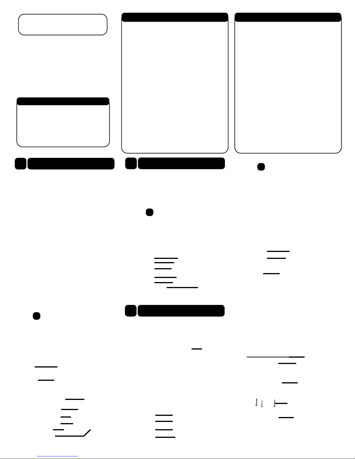
2.3
HD-CVI Glass Housing
Dome Cover
2
Dome Framework
Important
Dimensions of Cameras may vary depending on your
model. If you are having trouble nding the dimensions
you can nd the measurements by using a caliper or a
ruler. To nd the circumference of the bottom of the
camera use the following formula: Diameter of circle x
3.14(pi)
2.1
HD-CVI Metal Housing
Lens
Dome Body
Decoration Ring
Power
Video
SD/HD switch control cable
3
Dome Installation
Important
Before the installation, please make sure the installation
surface can sustain at least 3 times the weight of the
bracket and the camera.
HD-CVI Metal Housing
Pedestal 1
2.2
HD-CVI Plastic Housing
Lens
Dome Body
Decoration Ring
Step 1
HD-CVI Plastic Housing
Please take the installation position map from the
accessories bag, and then paste it on the ceiling or the
wall according to your monitor area requirements. Draw
and then drill three holes in the installation surface and
then insert three expansion bolts in the holes. Secure
these three bolts rmly.
Ceiling or Wall
Expansion Bolt
Dome Enclosure
IR Light
Dome Module
Dome Pedestal
Power Input Port
Video Output Port
SD/HD Switch Cable
Step 1 Adjust Monitor Angle
Turn the pan base to the pedestal to loosen or secure
rmly. Adjust and rotate base and the dome body to
get the lens to the proper monitor angle.
B1 Pedestal
B2 Pan Base
B3 Rotate Base
B4 Dome Body
Dome Camera Body
ST3 Self-tapping Screws
Decoration Ring

Step 2
Turn counter clockwise to remove the decoration ring.
Please drill a “cable exit hole” in the surface according
to the installation position map if you want to draw
out the cable from the top of the installation surface.
You need to draw out the cable from the cable channel
side port of the pedestal if you want to draw out the
cable from the side port of the cable channel. Adjust
the device installation pedestal to the proper position
and then draw the cable through the cable exit. Line up
the three screw holes in the installation position. Put
the three self-tapping screws in the three plastic
expansion bolts rmly. Now the dome camera is secure
in the installation surface.
Step 3
Adjust the lens to get a clear view of the area you want
to monitor.
Adjustment Screw
Cross-head Screwdriver
Step 4
Line up the decoration ring to the neck of the camera
body and tighten in place. Push and then turn
decoration ring clockwise. e installation is completed
aer you secure the decoration ring. You need to use the
proper tool to open up the side port of the U-cable
channel of the decoration ring if you want to draw out
the cable from the side port of the cable channel when
you are installing the device cable. en you can draw
out the cable from the cable channel of the pedestal.
Finally you can install the decoration ring to complete
the installation.
HD-CVI Glass Housing
e dome camera is usually installed on a ceiling.
Although, It could also be installed on a wall. you
secure the screws on the pedestal, please pull the cable
through the cable exit of the pedestal.
Do not remove the electrostatic lm until the
installation is completed. Aer you remove the lm, do
not touch the enclosure in case there is any scratch.
Step 1
Take the installation position map from the accessories
bag and put it on the surface of the ceiling or the wall
according to the cable exit position. Drill three holes
according to the installation position map and then take
three expansion bolts from the accessories bag and put
them into the holes you just drilled.
Ceiling or Wall
Installation Position Map
Expansion Bolts
Self-Tapping Screw
Enclosure fastening screw
Inner Hex Wrench
Step 2
Use the inner hex wrench to remove the three enclosure
fastening screws and then remove the dome enclosure.
Step 3
Adjust the pedestal position according to the cable exit
move(ceiling/side). Pull the cable through the cable
side exit at the installation surface and the pedestal.
(Please skip this step if you are mounting on a ceiling).
Line up the screw holes at the bottom of the pedestal to
the expansion bolts in the installation surface. Put three
self-tapping screws to expansion bolts and then secure
rmly. Now the pedestal is on installation surface.
Step 4
Adjust the camera module angle to a proper position
and then x the screws to fasten.
Fastening Screw
Step 5
Use three enclosure fastening screws to secure the dome
housing on the pedestal.
Step 2
Unscrew the screws on the bracket and adjust the
camera to the exact location which needs to be
monitored by rotating the bracket and camera body,
then secure the bolts.
VariFocal Camera
Unscrew M2 5*5 Bolt from the
lower cover of the camera. Remove
the Cover and adjust the VariFocal
(zoom) to your preference.
Lens Focal Lens
Lower Cover
M2 5*5 Bolt
4
Bullet Framework
Important
Dimensions of Cameras may vary depending on your
model. If you are having trouble nding the dimensions
you can nd the measurements by using a caliper or try
your best using a ruler. To nd the circumference of the
bottom of the camera use the following formula:
Diameter of circle x 3.14(pi)
Sun Shield Cover
Lens
Bracket
6
Menu
HD-CVI Series DVR settings
e following operation and interfaces is for reference
only. Please refer to the HD-CVI series DVR user’s
manual for detailed information.
Aer connecting the camera to the HD-CVI series DVR
go to Main Menu ->Setting->System->PTZ. You need to
set control mode as HD-CVI and the protocol as
HD-CVI. Click save button to save current setup.
5
Bullet Installation
Important
Before the installation, please make sure the installation surface
can sustain at least 3X weight of the bracket and the camera.
2 Megapixel Camera
Step 1
Before you install the bracket, please pull the cable
through the cable exit of the bracket chassis. install the
expansion bolt if you want to install in cement wall
and then you can install the bracket. If you want to
install in a wood surface, please skip the rst step and
then use the self-tapping screws to install the bracket
directly
On the preview interface, right click mouse and then
select PTZ; you can see an interface shown as below.
Click Iris “+” to open menu or conrm current
operation. Click up/down button to view all the items
on the le pane of the following list. Click le/right
button to set the corresponding values on the right pane
of the following list. If there is , click conrm
button to go to the 2nd menu. Repeat the previous steps
to set detailed value. Click return button to go back to
the previous menu interface.
 Loading...