

Page 1
1 Description
500-23700_A
WSS Wave Sense™ Switch
Installation Instructions
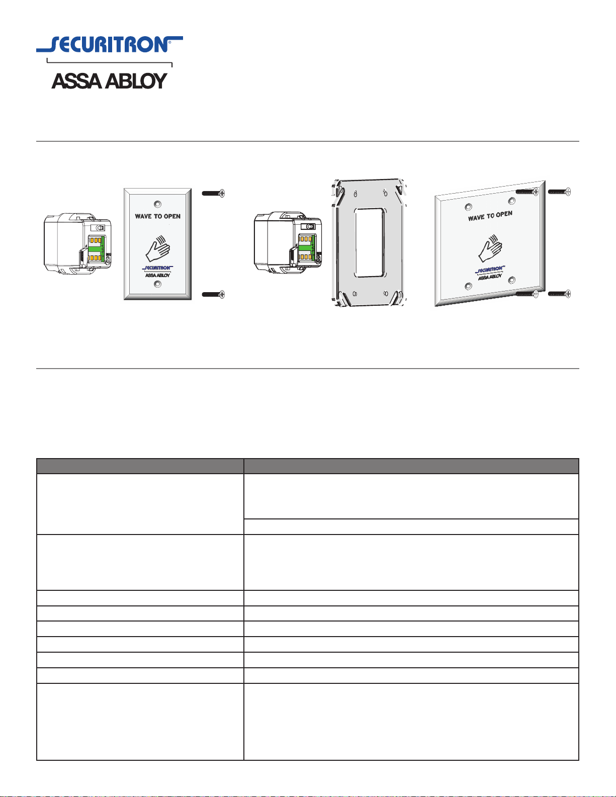
Screw
Microwave
Motion
Sensor
Screw
Faceplate
Microwave
Motion
Sensor
Adapter Ring
DOUBLE GANGSINGLE GANG
2 Package Contents
Microwave sensor Faceplate Adapter ring (double-gang model only)
Weather-resistant gasket Faceplate screws
Mounting ring Instructions
Description Specication
ELECTRICAL
OUTPUT
Relay contact rating (max voltage)
Relay contact rating (max current)
Max switching power
INPUT 12 to 24VAC ±10%
12 to 24VDC +30%/-10%
50 to 60Hz
<1.5W
Relay with switch-over contact (voltage free)
60VDC/125VAC
1A (resistive)
30W (DC)/60VA (AC)
Screws
Screws
Faceplate
DETECTION RANGE 4” to 24” (10cm to 60cm)(adjustable)
DETECTION MODE Motion (bidirectional)
OUTPUT HOLD TIME 0.5s (in pulsed mode)
OPERATING TEMPERATURE -4°F to +131°F (-20°C to +55°C)
IMMUNITY Immune to electrical and radio frequency interference
WEIGHT 0.34 lbs. (0.15 kg.)
REGULATORY Electromagnetic compatibility (EMC) according to
2004/108/EC
FCC: G9B-MS08
IC: 4680A-MS08
Page 2
3 Precautions
500-23700_A
☐ Shut off power to power source before attempting any wiring procedures.
☐ Maintain a clean and safe environment when working in public areas.
☐
☐
unexpected reactions by the door.
☐ Observe proper protocols for circuit board handling to protect the unit from electrostatic discharge.
Before handling any board ensure you dissipate your body’s charge.
☐ Check placement of all wiring before powering to ensure that moving door parts do not
catch wires and cause damage to equipment.
☐ Ensure compliance with all applicable safety standards (i.e. ANSI A156.10/A156.19) upon
completion of installation.
☐ DO NOT attempt any repair of the sensor. Unauthorized disassembly or repair:
1. May jeopardize personal safety and may expose one to the risk of electrical shock.
2. Will void the product warranty.
4 Installation/Wiring/Setup
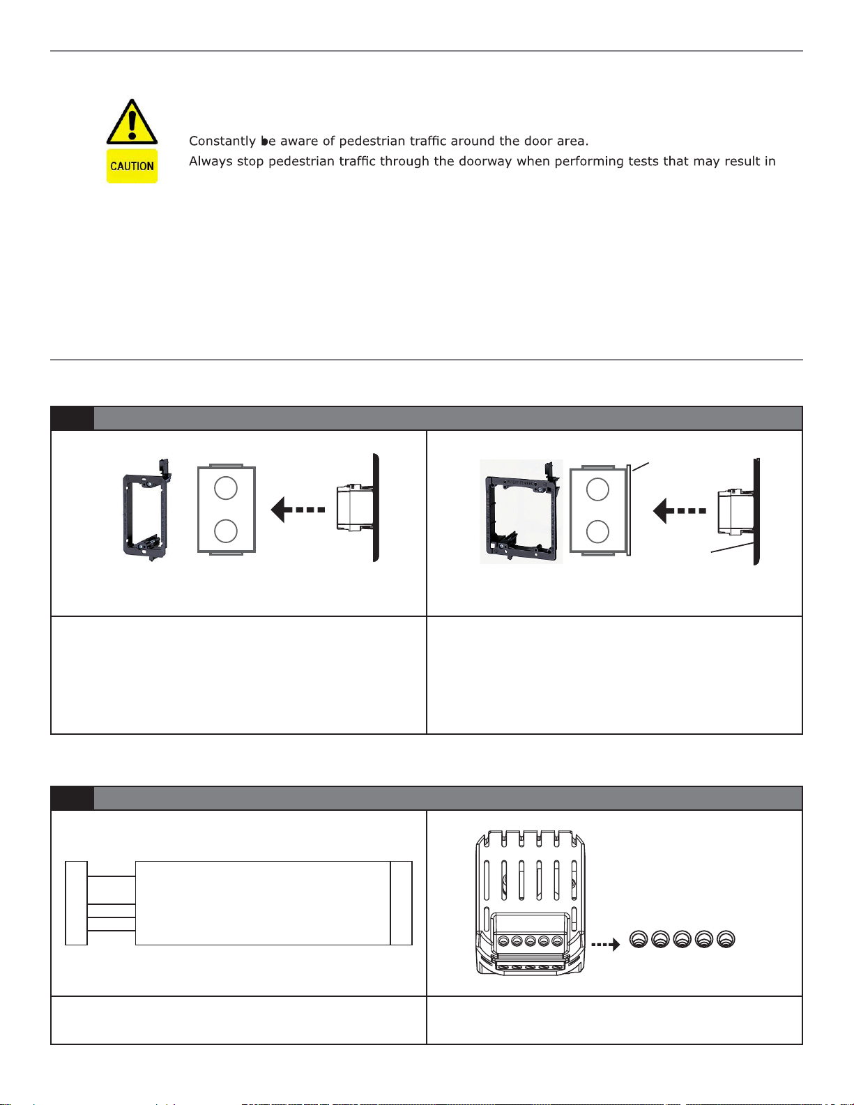
1 Installation
Adapter Ring
Mounting
Ring
Gang
or
Box
WSS
Assembly
1. The WSS may be mounted using the included mounting
ring or in a standard plastic or metal electrical gang
boxes. Do not allow contact between the sensor and
a metal gang box to prevent shorting the devices. Be
sure to place the device so that motion from the door
or other types of movement do not interfere with the
detection zone.
2 Wiring
●
PWR: Black - 12 to 24 VAC/VDC: -5% to +10%
●
W
S
S
PWR: Red - 12 to 24 VAC/VDC: -5% to +10%
●
NC: Empty - NC Contact
●
NO: Green - NO Contact
●
COM: White - Common at Door Control
C
O
N
T
R
O
L
Mounting
Ring
Gang
or WSS
Box
Foam Gasket
Assembly
2. Depending on the door installation, the weather resistant
foam gasket or the plastic adapter ring may be used.
The weather resistant foam is used as a protective
b
arrier against the elements. The plastic adapter ring is
designed to enable the double gang face plate to attach
to various plastic and metal gang boxes.
24 VAC / VDC
Black - 12 to
Red - 12 to 24 VAC / VDC
White - Com at Door Control
Green - NO Cotact
Empty - NC Contact
NC NO COM POWER
NC NO COM POWER
1. Wire the 4-conductor cable as shown above. 2. Attach the 4-conductor cable connector to the WSS
as shown.
Page 3

4 Installation/Wiring/Setup (Continued)
Toggle Mode
500-23700_A
3 Setup
Potentiometer
4”
24”
Output Mode Switch
Pulse Mode
4”
WSS Sensing Field
24”
1. Adjust unit to desired setup. Two adjustments can
be made to the sensor. The Potentiometer is used
3. Adjust Output Mode by moving switch in the up position
(Toggle Mode) or in the down position (Pulse Mode).
to adjust the size of the units’ sensing eld and the
Output Mode switch is used to select Toggle or Pulse
mode.
Toggle Mode: Recommended for switch applications. In
Toggle mode a detection activates the relay
and a second detection deactivates the
2. Rotate potentiometer clockwise to increase the sensing
relay.
eld. It may be adjusted from 4” to 24”.
Pulse Mode: Recommended for automatic door
applications. In Pulse mode a detection
activates the relay for a short period of time
- depending on the duration of movement in
front of door.
5 Troubleshooting
1 Troubleshooting Procedures
PROBLEM PROBABLE CAUSE CORRECTIVE ACTION
Door does not open when swiping
hand in front of sensor.
Door remains permanently open. 1. Environmental conditions are
The door remains open after
detection/activation
1. Bad or no power supply.
2. Detection range is too small.
3. Wrong connection.
inuencing the sensor.
2. Wrong connection.
1. Wrong output mode.
2. Wrong connection
1. Check power supply. If LED
switches on or ashes, power
connections are OK.
2. Adjust the detection range.
Remove any metal plates in
front of sensor.
3. Check wiring and relay
connection.
1. Remove any moving objects
close to the sensor.
2. Check wiring and relay
connection.
1. Switch the output mode to
Pulse mode.
2. Check wiring and relay
connection.
Securitron Magnalock Corp
Tel 800.624.5625
FCC APPROVAL
This device complies with Part 15 of the FCC Rules and with RSS-210 of Industry Canada.
Operation is subject to the following two conditions:
1. This device may not cause harmful interference, and
2. This device must accept any interference received, including interference that may cause undesired operation.
This equipment has been tested and found to comply with the limits for a Class B digital device, pursuant to part 15 of the FCC Rules. These limits are designed to provide
reasonable protection agianst harmful interference in a residential installation. This equipments generates, uses and can radiate radio frequency energy and, if not installed and
used in accordance with the instructions, may cause harmful interference to radio communications. However, there is no guarantee that interference will not occur in a particular
installation. If this equipment does not cause harmful interference to radio or television reception, which can be determined by turning the equipment off and on, the user is
encouraged to try to correct the interference by one or more of the following measures:
*Reorient or relocate the receiving antenna
*Increase the separation between the equipment and receiver
*Connect the equipment into an outlet on a circuit different from that to which the receiver is connected
*Consult the dealer or an experienced radio/TV technician for help
WARNING: CHANGES OR MODIFICATIONS TO THIS EQUIPMENT NOT EXPRESSLY APPROVED BY BEA INC. MAY VOID THE FCC AUTHORIZATION TO OPERATE THIS EQUIPMENT.
www.securitron.com
techsupport@securitron.com
 Loading...