

Securitron Vista V2M1200, Vista V2M1290 Installation Instructions Manual
1
500-33705, Rev A
V2M1200/1290 Series Maglock
Installation Instructions
Securitron
Phoenix, AZ 85044
Tel: 1-800-624-5625
Mon-Fri: 6:00am - 4:00pm PDT
Fax: 1-800-232-7329
www.securitron.com

2
500-33705, Rev A
Table of Contents
Product Information ................................................................................ 3
Electrical .............................................................................................. 3
Product Type ....................................................................................... 3
LED Operation Colors for V2M1200/1290 with MBS .................... 3
Recommended Tools ............................................................................. 3
Ensuring Correct Voltage Setting ........................................................ 4
Installing the V2M1200/1290 on an Out-Swinging Door .................. 4
Determining the Door Frame Header .............................................. 4
Installing the Armature Plate on a Solid Door ................................ 5
Installing the Armature Plate on a Hollow Door ............................. 5
Installing the V2M1200/1290 on an In-Swinging Door ..................... 6
Wiring the V2M1200/1290 .................................................................... 9
Electrical Specifications ..................................................................... 9
Typical Magnetic Lock Wiring ........................................................... 9
Wire Gauge Chart .............................................................................. 9
Magnetic Lock Care and Maintenance ............................................. 10
Troubleshooting .................................................................................... 10
VistaCare Warranty .............................................................................. 11

3
500-33705, Rev A
Product Information
Holding Force
1200 lbs (544 Kg)
Dimensions (L x W x H)
10-1/2” x 2-7/8” x 1-9/16” [266 mm x 72 mm x 40 mm]
Electrical
NOTE: Factory default setting is 24 VDC.
12 VDC and 24 VDC operation (field selectable via voltage selection
switch in the wiring compartment)
Product Type
NOTE 1: The V2M1200/1290 Series with Magnetic Bond Sensor
(MBS) uses a hall-effect sensor.
NOTE 2: The V2M1200/1290 Series with Door Position Switch (DPS)
uses a change-over reed switch sensor.
Besides the unmonitored version, the V2M1200/1290 Series Maglock is
available with either a MBS, a DPS, or both.
LED Operation Colors for V2M1200/1290 with MBS
The LED operation color can be set in the field. Colors can be reversed
by reversing the two-pin plug connection on the Printed Circuit Board
(PCB). The factory default setting is as follows:
LED indicator OFF No power to the magnet
LED indicator RED Power on magnet, door open
LED indicator GREEN Power on magnet, door closed
Recommended Tools
Screwdriver, #2 Phillips Center Punch
Drill Drill Bit: 15/32” [12 mm], 5/8” [16 mm],
Tap: ¼”-20 UNC [M6-1.0]
4
500-33705, Rev A
Ensuring Correct Voltage Setting
NOTE: Factory default setting is 24 VDC.
1. ENSURE the onboard PCB is set for the correct and desired
operating voltage.
2. IF a change is required,
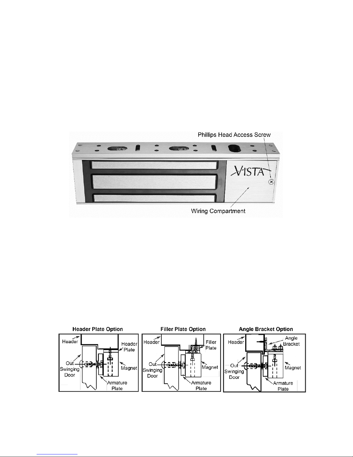
THEN ACCESS the wiring compartment by removing the wiring
compartment Phillips head screw and cover (see
Figure 1, “Wiring Compartment”),
AND TOGGLE the 12V/24V slide switch to the desired position.
Figure 1. Wiring Compartment
3. REPLACE the cover and Phillips head screw.
Installing V2M1200/1290 on Out-Swinging Door
Determining the Door Frame Header
1. DETERMINE the type of door frame header and whether a filler
plate, header bracket, or angle bracket is required for installation
(see Figure 2, “Door Frame Installation Options”).
Figure 2. Door Frame Installation Options
 Loading...