

Page 1

Copyright, 2000, all rights reserved • Securitron Magnalock Corp., 550 Vista Blvd., Sparks NV 89434, USA
Tel: (775) 355-5625 • (800) MAGLOCK • Fax: (775) 355-5636 • Website: www.securitron.com
An ASSA ABLOY Group company
PN# 500-17700 Page 1
Rev. A.1, 8/00
SECURITRON MODEL TSH TOUCH SENSE HANDLE
INSTALLATION AND OPERATION INSTRUCTIONS
1. DESCRIPTION
Securitron's Model TSH is an exit device for doors secured by electric locks. It can be employed
as a door push or pull and is particularly well suited for aluminum frame glass doors. The
assembly consists of a plastic base with an electronic touch sensor mounted inside and an
aluminum handle which is used to pull or push the door open.. When the handle is touched, a
relay in the sensor is tripped, releasing the lock. The relay contacts are double pole with the
second pole being optionally employed to shunt either an alarm system or the alarm function of
an access control system. The unit’s sensitivity is adjustable. In the unlikely event of sensor
failure, a push switch is mounted on the plastic base. Depressing the switch has the same effect
as activating the sensor by touch and therefore represents built in safety redundancy. The TSH
cannot be used outside in rain conditions.
As the TSH is normally used to allow egress on an electrically secured door, make sure
that you are complying with applicable building codes for your area. Check with your
local building department and/or fire prevention department.
2. PHYSICAL INSTALLATION
First, unscrew the handle from the plastic base (large Phillips screws) to reveal the base
mounting holes. Put the handle aside for now as initial mounting procedures concern the base.
2.1 MOUNTING HOLE DRILLING
Use the supplied template to set drilling positions for the two mounting holes. There are two
different hole diameters depending on the door type. Hollow metal doors employ supplied
machine screws and "blind nut" fasteners. The second method is to simply use wood screws (not
supplied) on a solid wood door. By "solid wood", we mean a hardwood interior rather than
pressed wood as the wood needs enough structural integrity to hold wood screws. Note however
that when the TSH is used on a solid door, the door must be core drilled to get the wire way cable
to the hinge side for take-off via the supplied door cord. For other door types, such as a chalk
filled fire door, consult the factory for additional mounting accessories. Note that the Touch
Sense Handle may not be used on a fire rated door that requires a fire rated latch (the TSH
has no latch), but sometimes fire doors are used on openings where a fire rated barrier is not
required, because the door type has been selected for other reasons (such as solidity).
For a hollow metal door, drill two 3/8" (9.5MM) diameter holes only deep enough to get through
the inner side of the door- not completely through the door.
For a solid wood door, you may elect to mount the handle with wood screws (not furnished).
We recommend 1 3/4" #14 wood screws with a hex, pan, oval or round head. Drill two 3/16"
(5MM) diameter holes to a depth of 1 1/4" (32MM).
2.2 WIREWAY HOLE DRILLING
The TSH connects to its power source and to the devices it controls via a six-conductor cable
with push-on connector (supplied). Exit from the door may be via the supplied door cord which
may be mounted at the top of the door where it is out of the way, or via any of many commercially
available transfer hinges or pivots which serve to route the wiring off the door in a concealed
manner. A 3/8" (9.5MM) wireway hole is then drilled into the door. Note that the template is
handed. The TSH can be vertically flipped to suit a right hand or left hand door but you have to
know which way the aluminum handle will face in order to correctly orient the template.
2.3 MOUNTING THE PLASTIC BASE TO THE DOOR
In the case of a hollow metal door, identify the two supplied blind nuts. The nuts are used as
follows. Insert the nuts with the knurl engaging the edge of each hole. Then utilize the supplied
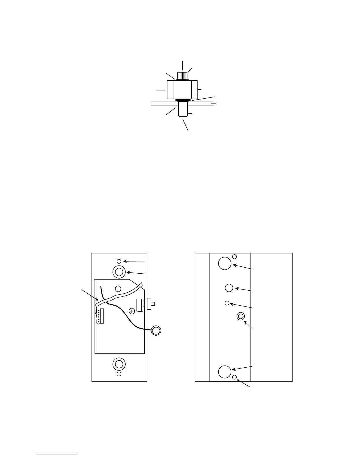
collapsing tool to collapse the nuts. Use of the tool is shown in Figure 1. Then, place a tooth
washer under the head of each screw and mount the plastic base. Do not over torque.
Page 2
Rev. 8/00 Page- 2
FIG. 1: COLLAPSING THE BLIND NUTS (METAL DOOR)
DOOR
TOOL
CAP SCREW
BLIND NUT
DRILL 3/8" (9.5MM) HOLE
NUT AS SHOWN
PRESS IN BLIND
COLLAPSES WHEN CAP SCREW
TURNED WITH ALLEN WRE NCH
WHILE TOOL HELD FAST
WITH BOX WRENCH
WHILE TURNING WITH ALLEN
WRENCH, PRESS IN TO KEEP
NUT SEATED IN DOOR
HOLD WITH WRENCH OR
CAP SCREW
VISE GRIP WHILE TURNING
-1/4-20 X 1"
FLAT WASHER
KNURL
2.5 ELECTRICAL CONNECTIONS WITHIN PLASTIC BASE
These connections must be made before the handle is attached to the base. First, the cable
connector must be correctly routed across the circuit board and plugged into the corresponding
connector on the board. See Figure 2 and note the correct cable routing and orientation of
plugging it in. Second, note that there is a free brown wire with a toothed ring terminal on its end
soldered into the circuit board. This is called the “antenna wire”. It must make conductive
contact with the aluminum handle to allow a person’s touch to be detected. Figure 2 also shows
the handle. A machine screw is “parked” in the antenna hole in the handle. Remove this screw,
run it through the ring terminal and then replace it in the same hole. You are now ready for
final installation of the handle on to the base.
FIG. 2: PLASTIC BASE AND HANDLE DETAIL
PLASTIC BASE
CIRCUIT BOARD
ANTENNA WIRE
WITH RING
TERMINAL
BACKUP
SWITCH
POT
ROUTE
CABLE
CONNECTOR
AND PLUG
IN AS SHOWN,
POSITION
FEMALE
CONNECTOR
TO RIGHT OF
CABLE (NOTE
RED MARKS
ON CONNECTOR FACE
TOWARDS
EDGE OF
CIRCUIT
BOARD)
ALUMINUM HANDLE
MOUNTING
HOLE TO BASE
MOUNTING
HOLE TO BASE
HOLE TO VIEW
LED
POT ACCESS
HOLE
ANTENNA WIRE
MOUNTING
HOLE
PLAQUE MOUNTING HOLE
LED
HANDLE MOUNTING
HOLE
MOUNTING HOLE
TO DOOR
CABLE ENTERS
DOOR OVER NOTCH
Page 3
Rev. 8/00 Page- 3
2.6 MOUNTING THE HANDLE TO THE PLASTIC BASE
Reinstall the handle on to the base by using the two large flathead Phillips screws. You will be
later sliding a plastic plaque into the handle but don’t do this yet. You will first need to wire the
unit and then adjust the sensitivity.
3. ELECTRICAL CONNECTIONS
3.1 SENSOR WIRING
The TSH has 6 colored wires which are for sensor power and DPST relay output:
Red - "+" DC Power
Black - "-" DC Power
White - Relay Common, Pole 1
Green - Relay Normally Closed, Pole 1
Blue - Relay Common, Pole 2
Orange - Relay Normally Open, Pole 2
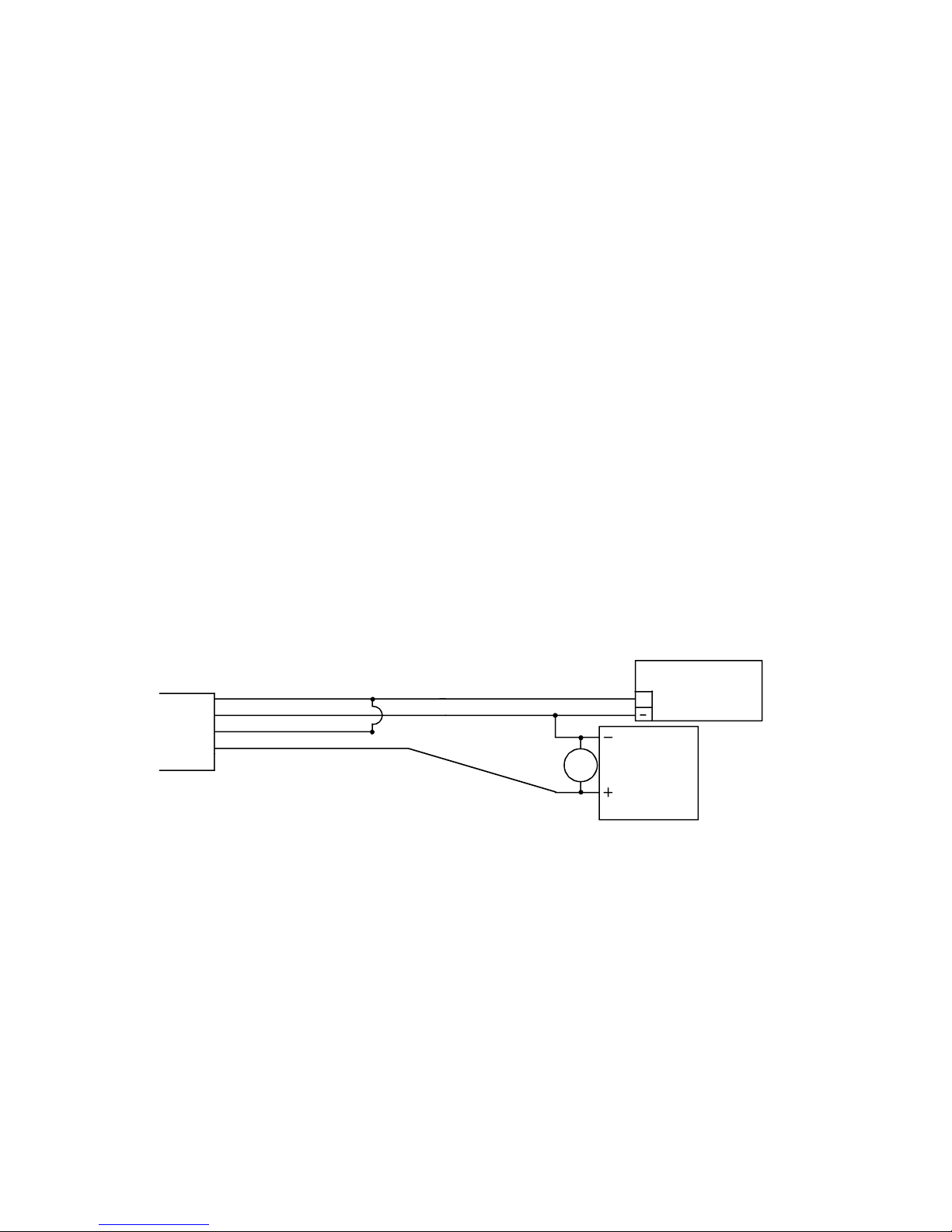
The relay has 2 amp contacts and when the handle is touched, the relay energizes. Note that the
contacts will also switch if the TSH loses power. For additional safety, the operation of the TSH
is fail safe, itself. When the TSH receives power, its control relay automatically energizes. It
deenergizes when the unit is touched. For applications releasing an electric lock, Figure 3 shows
typical connections of sensor, power supply and fail safe (locked when powered) electric locks.
Fail secure electric locks are normally not used with the TSH on required exit applications. N.O.
contacts, however, are available from the sensor for special signaling applications and for
integration with the Request to Exit (REX) function of an access control installation, as will be
explained. Note installation of the MOV in parallel with the electric lock. The MOV is supplied
loose with the TSH. It is a black or blue disk-like component with two bare wires. The MOV
suppresses inductive kickback from the lock which shortens the life of the relay contacts if not
suppressed. It should be spliced in as close to the electric lock as possible. It has no polarity. If,
however, Securitron's Magnalock is used in the installation, the MOV is not necessary as
the Magnalock is internally suppressed.
FIG. 3: TSH WIRING FOR FAIL SAFE ELECTRIC LOCK
The sensor operates on 12-24 volts DC and is normally powered by the same power supply that
operates the electric lock. When connecting power, polarity must be observed. Note that the
sensor draws 40 mA when "at rest" and 25 mA when it is releasing the lock. As an additional
safety feature, the TSH includes a low voltage sensing circuit. The unit will keep working
normally if input voltage declines until it reaches roughly 9 volts. At that point, the TSH will
automatically act as if all power was removed. If a lock is being controlled, it will release. Input
voltage could decline if the unit was being operated on batteries and the batteries were
discharging or because of a fault in the power supply.
CABLE
RED (+ POWER)
BLACK (- POWER)
WHITE (RELAY COM1)
GREEN (RELAY N.C.1)
POWER SUPPLY
12-24 VDC
+
MOV
MAGNETIC
LOCK
NOTE 1: MOV NOT NEEDED IF SECURITRON MAGNALOCK USED
NOTE 2: POWER SUPPLY MUST ALWAYS CONNECT DIRECTLY TO SENSOR.
NOTE 3: POLARITY MUST BE OBSERVED WHEN CONNECTING POWER.
OTHER CONTROL SWITCHES SHOULD BREAK OR PARALLEL RELAY CONTACT S AS NEEDED.
Page 4

Rev. 8/00 Page- 4
3.2 DOUBLE BREAK WIRING
Many installations include a controlled access device such as a digital keypad or card reader.
Such devices typically have a REX (request to exit) input. When dry contacts close on this input,
the entry device will open the lock for the same amount of time that has been programmed for
entry. Use of the REX input for exit has two benefits: you pick up timed exiting and also with
most controls, the REX input must be used for exiting to avoid an alarm condition at the door.
If the REX input alone is used for exiting, a safety/reliability problem will exist. If the entry
device malfunctions, exit will not be possible and people may be trapped. We therefore always
recommend double break wiring which is supported by the TSH’s two pole relay. The TSH's NC
contacts are used to break power to the fail safe electric lock while its NO contacts trip the REX
input of the controlled entry device. This releases the lock a second time, hence the term,
"double break". If the controlled entry device fails for any reason, direct exit is still achieved.
FIG. 4: TSH DOUBLE BREAK WIRING
CABLE
RED (+ POWER)
BLACK (- POWER)
WHITE (RELAY COM1)
GREEN (RELAY N.C.1)
POWER SUPPLY
12-24 VOLTS
+
MOV
ACCESS CONTROL
REX INPUT
ACCESS CONTROL
LOCK CONTROL
NC CONTACTS
BLUE (RELAY COM2)
ORANGE (RELAY N.O.2)
MAGNETIC
LOCK
NC
NC
3.3 ALL SECURITRON EQUIPMENT INSTALLATION
Figures 3 and 4 show "generic" use of the Touch Handle with any type magnetic lock and power
supply. Often, Securitron supplies all of these products and the installer expects an
interconnection drawing for all Securitron products. We provide such drawings in many of our
manuals. In this case, the replacement of the generic products shown above with Securitron
products is so simple as not to require separate drawings. Just note that for any Securitron
Magnalock, the red wire denotes the "+" input and the black wire denotes the negative.
Remember that you don't need to install the MOV with any Securitron Magnalock. Securitron
offers a wide range of different power supplies, so it is necessary to consult the individual power
supply manual to identify the DC output terminals. Then connect the power supply outputs to the
rest of the system as shown above.
3.4 CAUTION ON USE WITH PROXIMITY CARD READERS
When a proximity card reader is used for entry and a Touch Handle is used for egress, there is a
small possibility of interference. The proximity reader projects an electric field of considerable
intensity and we have seen rare cases where this can be picked up by the TSH. It depends on
the power of the proximity reader and the nearness of the reader on the outside of the door to the
handle on the inside. To make sure a problem does not exist after the installation is complete,
perform the following test. Turn the sensitivity up as high as you can to the point just before it is
open all the time (see Section 3.6). Then, from the outside of the door, place your hand on the
reader and lean your body against the door to see if the handle can be triggered. The effect of
coupling the reader's energy though your body into the door, tends to increase the sensitivity of
the handle.
If you find that the unit triggers from this test, there is some interference. You have two options.
It may be that the interference is so little that when the sensor is adjusted down, there is no risk of
Page 5

Rev. 8/00 Page- 5
triggering from the outside. You can experiment with this. Alternately, Securitron has developed
a simple filter circuit which will absorb the interference from the reader. This requires a 22,000
Micro Henry inductor (DigiKey part # M7223-ND, JD Miller part # 70F222AI). You can purchase
this part at a local electronics parts supply house or from Securitron. To install the inductor,
identify the ring terminal with brown wire which connects the “antenna” screw on the back side of
the aluminum handle to the circuit board. Clip this wire and splice in the inductor. As the inductor
is an insulated part, it can lay in the cavity in the plastic base on top of the circuit board.
3.5 CAUTION WITH SWITCHING POWER SUPPLIES
The TSH is capable of being operated by a wide variety
of power supplies and does not require regulated power
but a certain class of power supplies called "switching"
can sometimes interfere with operation. Switching
supplies are unusual in the security industry. Most
regulated power supplies are of the "linear" type. Some
switching supplies can produce line noise which will affect
the TSH by rendering it hard to adjust. If you find that a
TSH is hard to adjust, check the power supply. If it is a switcher, the power supply can be
replaced with a linear Securitron unit or addition of two capacitors generally solves the problem.
Connect one .01 mF capacitor between power supply + and earth ground. Connect a second .01
mF capacitor between power supply negative and earth ground. See the drawing to the right.
3.6 ADJUSTING SENSITIVITY
With wiring completed, sensor adjustment should be set. Note that the sensor board has a
potentiometer on it accessible through a “pot access hole” from the top of the aluminum handle
before the plaque has been installed (see Figure 2). The potentiometer will increase sensitivity
when turned clockwise and decrease it when turned counterclockwise. Note the LED on the
sensor circuit board which is visible through an access hole in the aluminum handle (see Figure
2). This LED “follows” the sensor. It is on when the sensor is releasing the door. Turn the pot
clockwise without touching the handle until the LED just turns on. In this condition, sensitivity
is so high that the unit is on all of the time. Slowly rotate the pot counter-clockwise until you see
the LED turn off and then another 15 degrees counter-clockwise. This is generally a good
setting. Then, experiment by touching the handle and observe that the LED comes on.
Experiment with gloves if you expect that they will be used. You may want to increase the
sensitivity somewhat, but if you leave it just below the point where the LED comes on, you risk a
condition where the unit will fail by being on all the time.
3.7 USE OF REDUNDANT (BACKUP) SWITCH
A red push switch is mounted on the side of the plastic base. The purpose of this switch is to
provide backup in case of any malfunction or misadjustment of the sensor. Pushing the button
breaks the connection between the white (COM1) and green (NC1) wires just the same way as if
the handle was touched. It therefore provides a "hard" backup circuit break which will release the
controlled fail safe lock. It does not however affect the COM2 and NO2 circuit (blue and orange).
If these NO contacts are being used, for example, to provide REX input to an access control
system, pushing the backup button will not achieve this, but egress safety is maintained as with
the switch mounted, there are two independent controls which can release the door. In the event
that the sensor fails, the button will still work.
3.8 INSTALLATION OF PLAQUE
After wiring is complete, you will install a plastic plaque in the slot in the aluminum handle to
cover up the mounting holes and access holes to the circuit board. Note that the two supplied
plaques give you four choices. You can select a legend- either “PULL” or “PUSH”, depending
on which way the door swings. Alternately you can select the back side of either plaque which
will yield a plain finish in either a matching or contrasting color to the color of the handle
depending on your esthetic preference. To install the plaque, note that we have supplied a
choice of screw colors to match the plaque color that you select.
4. ELECTRIC LOCK SELECTION
Electric lock selection is important to obtain best results from the TSH. The product allows silent
and immediate egress without the mechanical action of traditional exit devices which require
periodic maintenance and replacement. Having no moving parts, the TSH possesses an
extended operating life. The product was designed for use with Securitron's Magnalock. The
SWITCHING
POWER
SUPPLY
.01 mF
.01 mF
EARTH GROUND
Page 6

Rev. 8/00 Page- 6
Magnalock secures the door with magnetic force only and therefore has no possibility of jamming
and thereby denying egress. The Magnalock also has internal electronics which allow it to
release very rapidly. When used with the TSH, which is also a fast device, exit is immediate and
the impression a person exiting gets is that the door is not locked at all. Other magnetic locks
generally operate significantly more slowly than the Magnalock. This makes egress less
convenient as a person must pause somewhat after touching the handle until the door releases.
5. OPERATIONAL SECURITY CONSIDERATIONS
In the typical use of the Touch Sense Handle, it provides free egress from the interior protected
area. The electric lock secures against unauthorized entry from outside. It is of important
concern that persons on the outside cannot activate the interior release device from the outside.
This is a common problem with other interior release devices. For instance, if a panic bar with
switch is used, it is possible to trip it from the outside if the intruder can introduce a coat hanger in
between the door and frame. Aluminum frame glass doors tend to allow this more than other
types. Similarly, microwave detectors used on the inside can sometimes be activated from the
outside if the door is vibrated strongly.
The Touch Sense Handle is more secure with respect to the outside. To assure this security,
however, the user must be made aware of certain operational characteristics. The sensor
functions by setting up an oscillating electric field which conforms along any metal surface that
contacts the sensor's antenna wire. In the Touch Sense Handle it is the handle itself that carries
the field. The electric field is disturbed by the near proximity of ionized fluids within the body,
which form a conductive mass. It is this mass that the sensor detects. As a proximity device, the
handle is sensitive to the closeness of the mass. For example, if a person wearing gloves
touches the handle with his finger tip, the door will generally not release. When the gloved hand
is wrapped around the handle in normal use, the door will release because the conductive mass
of the hand is in much closer contact with the handle.
The main security concern regarding outside entry is if a person could introduce a metal wire from
the outside and make metal to metal contact with the handle. The field could then propagate
along the wire and be activated by the intruder's hand. In practice, this is unlikely. The handle is
anodized and therefore insulated so it will not make contact with the wire. The intruder would
have to scratch away the anodization which requires both effort and knowledge. Also the field
propagates weakly along a thin wire. If, however, high security from the outside is critical in the
application, the sensitivity of the TSH should be set as low as satisfies the exit performance
requirements.
6. SENSOR REPLACEMENT
Should it ever be necessary to replace the sensor circuit board, it is done as follows: Remove the
two screws holding the plaque and slide out the plaque. Remove the two large flathead Phillips
machine screws and carefully remove the aluminum handle from the plastic base. As you are
removing the aluminum handle, note that it is connected to the base via a ring terminal with
brown wire screwed into the handle but soldered into the sensor circuit board. Unscrew the ring
terminal from the handle and put the handle aside. Next unscrew the red redundant backup
switch from the base. The backup switch is part of the sensor circuitry and the board will not
function without it. Finally, note that the board is held to the base via two Phillips machine
screws. Remove these screws and the board is ready for replacement.
APPENDIX A
TROUBLESHOOTING
PROBLEM- The door will not release when the handle is touched.
To monitor operation of the handle, it is quite easy to hear the relay click when the handle is touched. Alternately, if
you remove the plaque, you can monitor the LED which comes on when the handle senses touch. If you don't hear
a click (or see the LED come on), try the backup switch. If the door does not release from the backup switch, it is
almost certain that the overall wiring of the installation is at fault. If the door releases from the backup switch, the
general wiring is correct but the sensor is not reading your touch. Make sure you understand section 3.6 on how to
adjust sensitivity of the handle. It may be set too low. Another fault could be that the sensor itself is not receiving
12-24 DC power on the red and black wires. Check the power supply and, be sure the input polarity is correct.
Also, even if power is being applied on the red and black wires, it's possible that it's not getting into the sensor.
Page 7

Rev. 8/00 Page- 7
Check the connector block that plugs into the sensor card for loose wires. Finally, it is possible that the ring terminal
that connects the sensor to the handle itself has come loose. See Figure 2.
If you can hear this click (or see the LED come on) and the door does not release, try the backup switch. If the
door still doesn't release, the problem must be in the installation wiring as it is nearly impossible to have a failed
sensor relay and backup switch at the same time. Review your wiring to make sure the sensor is correctly applied in
the circuit. If you hear the click but only the backup switch releases the door, call the factory as the defect appears to
be in the relay contacts and the sensor will have to be replaced.
PROBLEM- The door remains released constantly
If you hear a click when you touch the handle but the lock remains released, the problem is probably in the wiring
which should be reviewed to be sure the sensor is correctly applied in the circuit. Note that you can monitor the LED
which comes on when the handle senses touch if you remove the plaque. If the LED is on constantly or if you
don't hear a click when you touch the handle, the sensor is probably adjusted too high (review section 3.6).
Rotate the adjustment pot counter-clockwise while not touching the handle. If this doesn't lock the door, some
effect is probably keeping the relay deenergized all the time (remember; the relay is energized when the lock is
secure to maintain fail safe operation).
The most likely cause for the relay to remain deenergized is that the sensor "sees" an overwhelmingly large signal as
if someone was continually touching the handle. This will happen if the handle is not properly isolated from a metal
door. Because of the plastic base, the intrinsic isolation of the handle from the door is many times greater than it
needs to be. Make sure that there is no "foreign object" creating a conductive path from the handle to the door. An
example would be metal blinds.
The same effect will occur if the handle is used outside in the rain or if water is flowing down the inside of the door.
This overcomes the electrical isolation needed between the handle and door.
Certain large electronic noise sources can "swamp" the sensor although this is rare. Examples would include large
radio or radar transmitters in the building or a high voltage neon sign mounted within a few feet of the door. Call the
factory if you suspect noise induced problems.
Finally, in very rare instances, the sensor can “hang up” in a condition that continuously releases the door. Depower the unit and turn the adjustment pot all the way counterclockwise. Then, re-power the unit and note that the
door locks. Then, readjust the sensor potentiometer normally.
IF YOUR PROBLEM PERSISTS, CALL SECURITRON: 1-800-MAG-LOCK
MAGNACARE LIMITED LIFETIME WARRANTY
SECURITRON MAGNALOCK CORPORATION warrants that it will replace at customer’s request, at any time for any
reason, products manufactured and branded by SECURITRON.
SECURITRON will use its best efforts to ship a replacement product by next day air freight at no cost to the customer
within 24 hours of SECURITRON’s receipt of the product from customer. If the customer has an account with
SECURITRON or a valid credit card, the customer may order an advance replacement product, whereby
SECURITRON will charge the customer’s account for the price of the product plus next day air freight, and will credit
back to the customer the full amount of the charge, including outbound freight, upon SECURITRON’s receipt of the
original product from the customer.
SECURITRON’s sole and exclusive liability, and customer’s sole remedy, is limited to the replacement of the
SECURITRON product when delivered to SECURITRON’s facility (freight and insurance charges prepaid by
customer). The replacement, at SECURITRON’s sole option, may be the identical item or a newer unit which serves
as a functional replacement. In the event that the product type has become obsolete in SECURITRON’s product
line, this MAGNACARE warranty will not apply. This MAGNACARE warranty also does not apply to custom, built to
order, or non-catalog items, items made by others (such as batteries), returns for payment, distributor stock
reductions, returns seeking replacement with anything other than the identical product, or products installed outside
of the United States or Canada. This MAGNACARE warranty also does not apply to removal or installation costs.
SECURITRON will not be liable to the purchaser, the customer or anyone else for incidental or consequential
damages arising from any defect in, or malfunction of, its products. SECURITRON does not assume any
responsibility for damage or injury to person or property due to improper care, storage, handling, abuse, misuse, or
an act of God.
EXCEPT AS STATED ABOVE, SECURITRON MAKES NO WARRANTIES, EITHER EXPRESS OR IMPLIED, AS
TO ANY MATTER WHATSOEVER, INCLUDING WITHOUT LIMITATION THE CONDITION OF ITS PRODUCTS,
THEIR MERCHANTABILITY OR FITNESS FOR ANY PARTICULAR PURPOSE.
Page 8

Rev. 8/00 Page- 8
 Loading...