

Securitron SWB-26D, SWB-03, SWB-10B Installation Instructions
Securitron Magnalock Corp. www.securitron.com ASSA ABLOY, the global leader
Tel 800.624.5625 techsupport@securitron.com
in door opening solutions
INSTALLATION INSTRUCTIONS FOR
SAM WOOD DOOR BRACKET SWB-03, SWB-10B, SWB-26D
1. INTRODUCTION
The SWB – SAM Wood Bracket is designed for various wood door applications. The SWB – SAM Wood
Bracket is designed for use on 1-¾” hard core style doors that include strike mounting applications that
are installed without the use of the end brackets. The SWB – SAM Wood Bracket reinforces the door to
maintain the strength integrity of the door after coring. The SWB – SAM Wood Bracket is available in three
(3) finishes. The finishes are as follows:
SWB-03 Polished Stainless Steel with Brass Finish
SWB-10B Brushed Stainless Steel with Resin Finish
SWB-26D Brushed Stainless with a #4 Grain Finish
2. SPECIFICATIONS
Bracket Dimensions:
Inches: 11”W X 2”H X 1.850”D
Millimeters: 280 W X 51H X 47 D
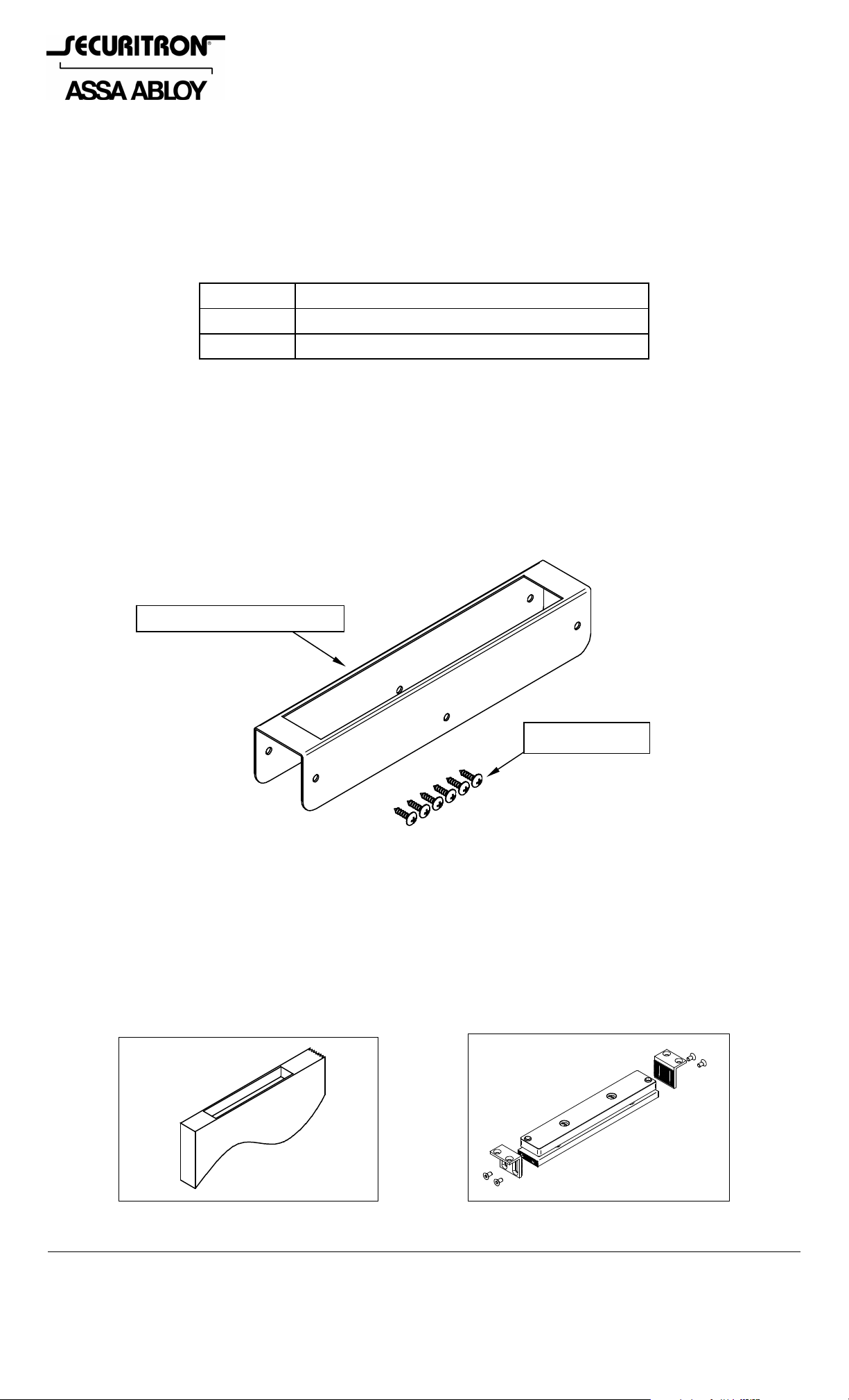
3. PRODUCT OVERVIEW
Upon unpacking this product, an inventory should be made to ensure that all the required components
and hardware have been included. Along with these Instructions this product should include the following
items:
SWB - SAM Wood Bracket
Hardware Pack
4. RECOMMENDED TOOLS
Phillips Screwdriver
Drill bit: 9/64”
5. INSTALLATION INSTRUCTIONS
5.1 Door Preparation and Strike Mounting
As expressed in Figure 1, route and chisel the strike mounting area in the door as noted in the
SAM, SAM2 Shear Aligning Magnalock manual Section 2.3.5. Disassemble the end brackets and
screws from the strike and set aside. Parts will not be needed for this installation.
Figure 1 Figure 2
© Copyright, 2011, all rights reserved PN# 500-22200
Page 1 Rev. C, 03/11
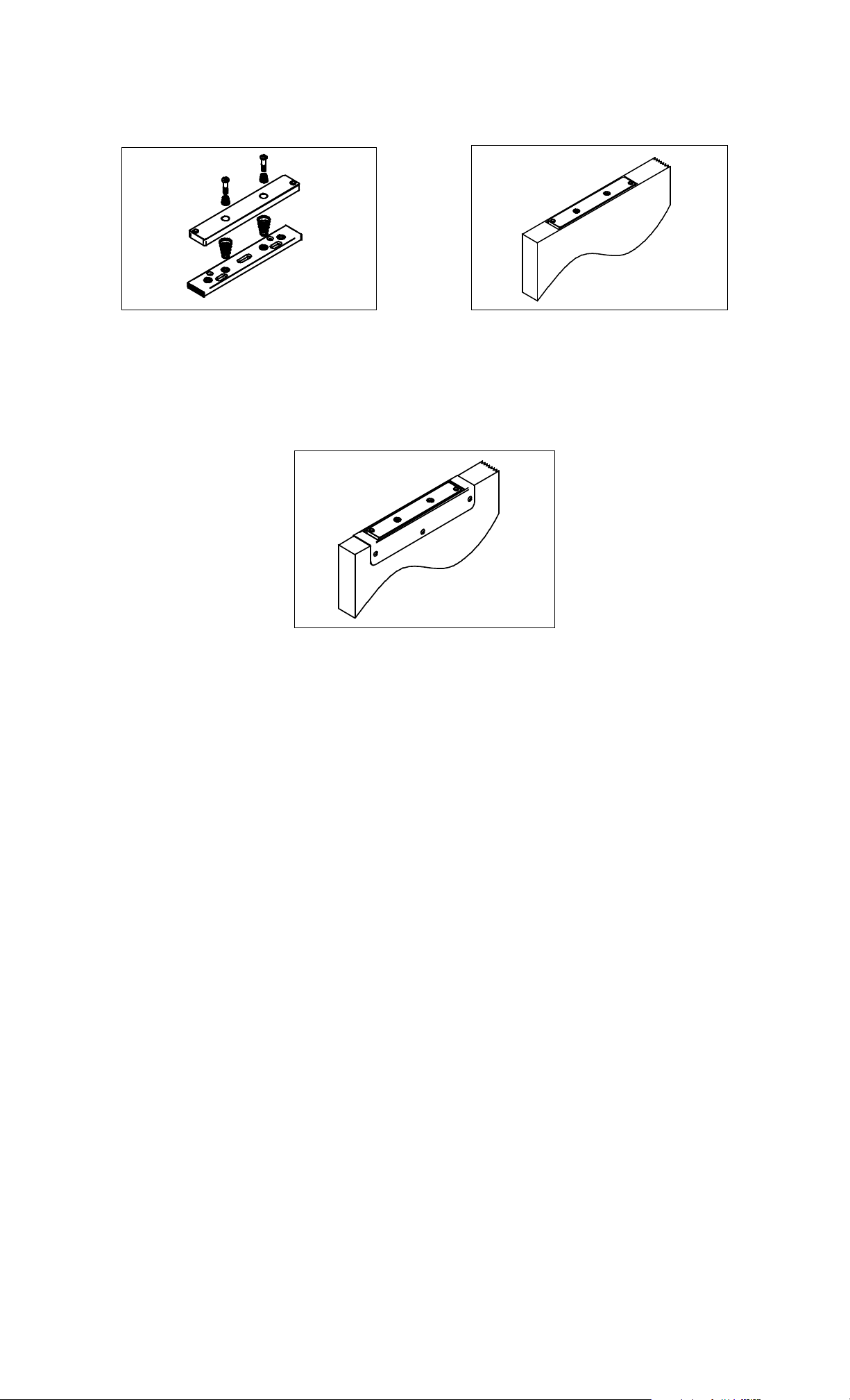
Disassemble the Strike from the Idle Bracket as shown in Figure 3. Mount the Idle Bracket as noted in
the SAM, SAM2 Shear Aligning Magnalock manual Section 2.3.5 using the #8 x ¾” screws provided.
Reassemble the Strike Assembly to the Idle Bracket as shown in Figure 4.
Figure 3 Figure 4
5.2 Reinforcement Bracket Installation
Place the reinforcement bracket on top of door and align over the strike assembly area. Mark the six
(6) holes on both sides of the door. Remove the bracket and drill the holes using the 9/64” drill 5/8” –
3/4” deep. Place the reinforcement bracket back on top of the door and install the six (6) screws
provided as shown in Figure 5.
Figure 5
PN# 500-22200
Page 2 Rev. C, 03/11
 Loading...