

Securitron MSS-1-RT, MSS-1, MSS-1G-RT, MSS-1G, MSS-1C-RT Installtion Instruction
...
Securitron Magnalock Corp. www.securitron.com ASSA ABLOY, the global leader
Tel 800.624.5625 techsupport@securitron.com
in door opening solutions
SECURITRON MODEL MSS-1 MAXIMUM SECURITY SWITCH
INSTALLATION & OPERATING INSTRUCTIONS
1. DESCRIPTION
Securitron’s maximum security magnetic switch is intended to monitor the open or closed
position of doors, windows, machinery safety barriers or other movable assemblies in critical
environments where an attempt to defeat the switch is a concern. The switch includes
numerous design features that make it highly defeat resistant, reduce false alarms and provide
for easy and accurate installation. It is available in two versions to deal with different physical
mounting conditions and may be used indoors or outdoors. Each version consists of two
pieces: the switch module and the magnet pack. The MSS-1 is mainly intended for use on doors
and includes a jacketed cable which can be hidden in the door frame. The MSS-1G provides a
stainless steel jacketed cable which is suitable for a range of applications where the cable can not
be hidden and must resist possible attack.
2. DEFEAT RESISTANCE ISSUES
The most common approach used to defeat a magnetic switch is to introduce an external
magnet near the switch module so that the door, window or other barrier can be opened without
the switch alarming. The MSS cannot be defeated in this way as its own magnet pack (which
contains a magnet array) must be used to put it into the secure state. If a very powerful
external magnet is used in an attempt to defeat the MSS, it may even put the MSS into alarm.
Another method which represents a more serious threat is when an intruder attempts to defe at
the switch by obtaining a second MSS magnet pack. If access to the MSS can be obtained, the
switch might be defeated by positioning the second magnet pack near the switch module in a
manner that permits the door to be opened without an alarm being signaled.
The MSS design includes two defenses against this risk.
The first is called co-planar operation. The switch
will only respond to the magnet pack if the pack is
located in roughly the same plane as the switch. A
second magnet pack placed in proximity to the switch
will not activate the switch because it will be o ff-plane.
In effect, there is only room for one magnet pack being
read by the switch at a time, so a second pack cannot
compromise security.
In certain physical situations however it may be
possible to slowly open the door and slowly introduce a
second magnet pack. The MSS includes an extra
defense against this. The product is manufactured in different types. The magnet pack
must be of the same type as the switch module to work. The MSS is delivered as a matched
pair with no marking that identifies its type. Therefore, a person attempting the difficult task of
trying to slowly open a barrier while introducing a second MSS magnet pack in an attempt to
defeat the switch may well have the wrong type pack.
Another attack possibility is removal of the switch module. This can serve several purpose s. It
can provide access to the cable (assuming the cable is hidden in the door frame). It can also be
part of an attempt to remove both the switch module and the magnet pa ck as a unit to permit
opening the door or window without triggering an alarm. To forestall this, the MSS includes a
hidden tamper switch feature. The tamper switch provides a two wire output which is
normally closed and opens if the switch is removed. This line can be separately monitored or
connected in series with the main switch output. See Section 3.
Finally, a very serious threat is removal of the magnet pack from the door. If the magnet pack
can be removed from the door and maintained at a correct distance from the switch module,
clearly the door can be opened without signaling an alarm. The MSS’s mounting methods
coupled with co-planar operation, however, preclude this. See Sections 3.2 and 3.3. To
conclude, in a security application, the MSS’s array of anti-defeat features will almost always
result in the alarm sounding while the switch is being tampered with. This can lead to the
person attempting to defeat the switch being identified and detained.
© Copyright, 2011, all rights reserved PN# 500-16700
Page 1 Rev. D, 03/13
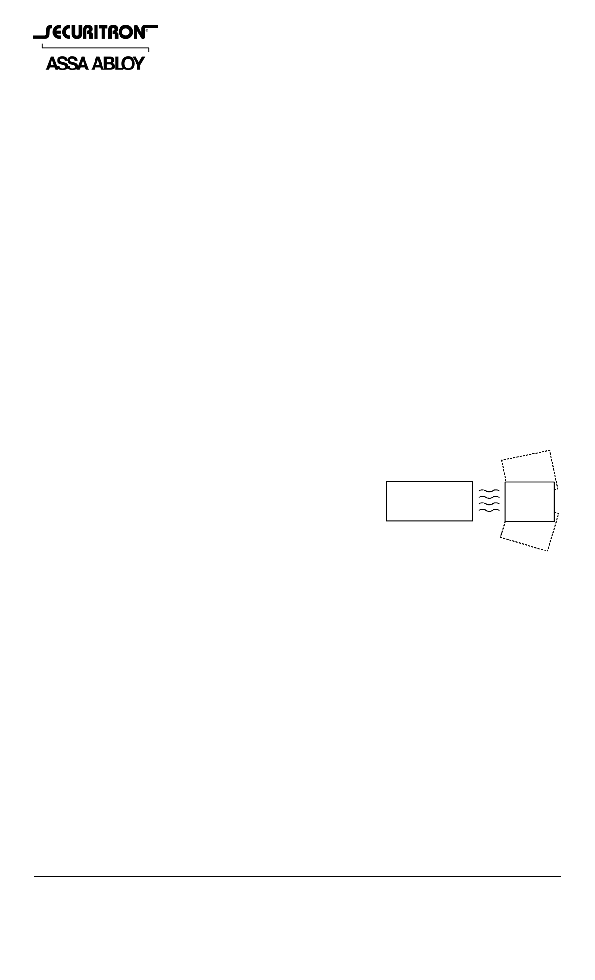
CO-PLANAR OPERATION
SWITCH
TO ENHANCE DEFEAT RESISTANCE,
THE MAGNET PACK CAN ONLY BE
READ IN A NARROW ANGLE
IN FRON T OF TH E SWITCH.
MAGNET
PACK
3. PHYSICAL INSTALLATION
The MSS can be used to monitor the opening of doors, windows, gates and barriers of all types.
The switch module is mounted on the part of the assembly that is fixed (such as a door frame)
and the magnet pack is mounted on the part of the assembly that moves (the door, for
example).
Unlike many magnetic switches, the performance of the MSS is unaffected by the type of
surface it’s mounted on. It will perform the same on steel as on wood.
In planning for mounting the MSS, note that the switch and the magnet pack have to be
oriented correctly, have to be roughly in the same plane and have to be a defined
distance apart.
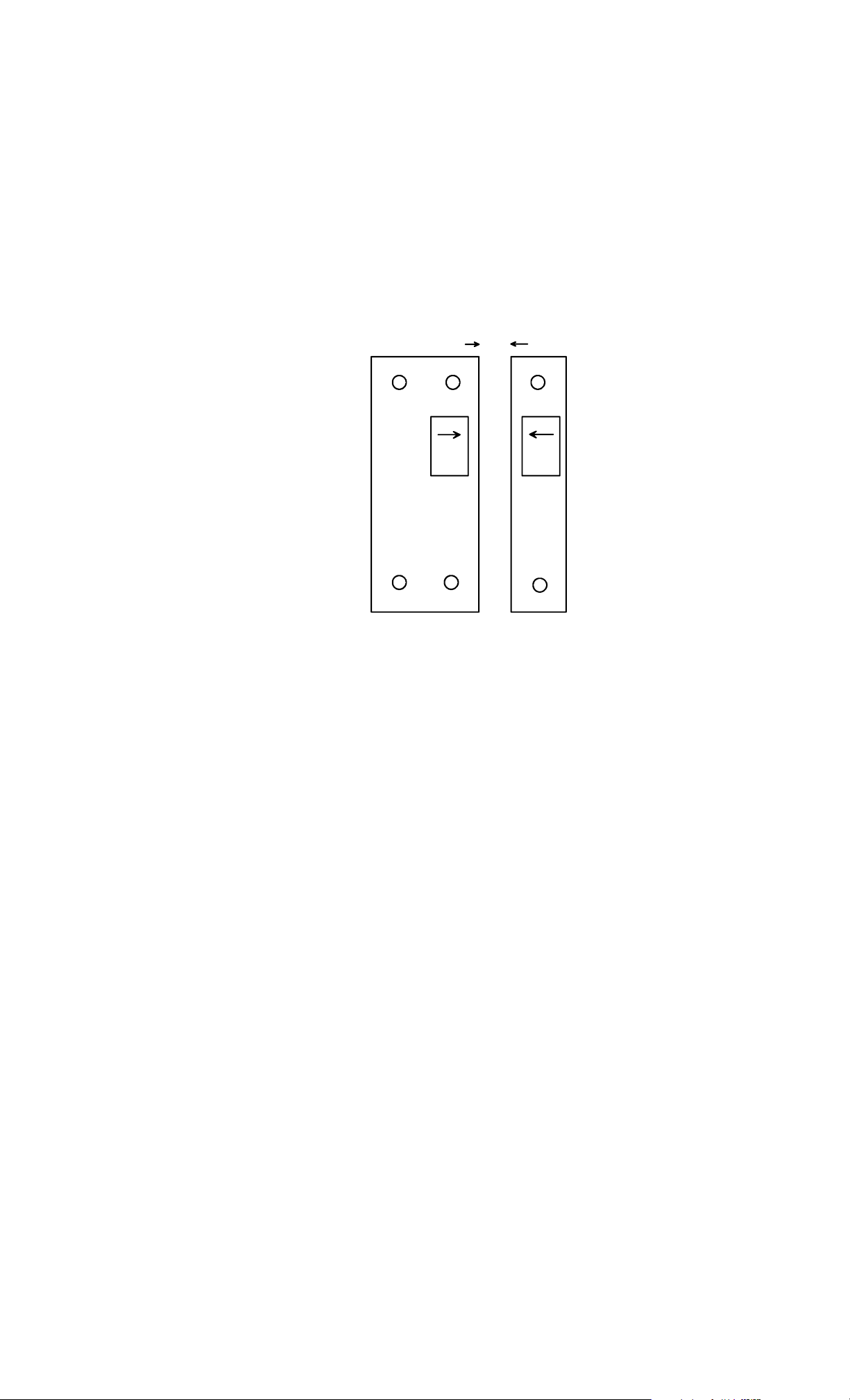
To obtain correct orientation, note the
SEPARATION DISTANC E
arrows on the labels on each
component. The arrows have to
directly face each other and the ends
of the two pieces must be even, not
offset.
The MSS includes a minimum and
maximum operating distance. The
unit will report secure only when the
separation distance is between this
maximum and minimum. If the
THE ARROWS ON THE SWITCH
AND MAGNET PACK MUST
FACE EACH OTHER AND
AND THE ENDS OF EACH
COMPONENT MUST BE
EVEN- NOT OFFSET.
SEPARATION DISTANC E IS
SPECIFICALLY NOTED FOR
EACH INDIVIDUAL PAIR.
magnet pack is too close to the switch
module or too far away, the unit will
alarm.
The distance between the minimum
and maximum separation points is called the gap. The MSS provides a gap of 4/10”-1/2”
(10-12.5MM). For best reliability, you want to set the actual separation distance exactly
midway in the gap. The gap will, however, vary somewhat on each unit and the minimum
distance at which the gap starts will also vary. You can, of course determine the optimum
midway separation distance by using a ruler and Ohmmeter but as part of our QC proce dure, we
have checked this distance and it is printed on the switch module label. Use this separation
distance when you mount the unit.
The tamper feature on the MSS works as follows. An oval h ead screw (supp lied) is set into the
surface which is to receive the switch module. Two metal washers are placed under the screw
head to yield the correct height. The template shows positioning of this screw. W hen the sw itch
module is installed, the tamper screw depresses the tamper switch. This closes the two wire
tamper circuit. Note that if you push the tamper switch in with a pa per clip for example, you’ll
hear it click. This is not the switching point. Switching occurs much earlier in the travel so that
the height of the screw head will always move the tamper switch past its switch point but will
not bottom it out which could damage the tamper switch. Make sure, however that you place
the two metal washers under the tamper screw head and then screw it down flush
with the mounting surface. This sets up the correct height of the screw head. Note also the
fact that the switch module is tampered is undetectable and any attempt to remove the switch
module will open the tamper circuit. This circuit may be directly monitored (usually by a 24
hour circuit) or connected in series with the closed loop of the main switch output such that a
tamper violation will create the same alarm signal as if the door was opened.
3.1 CABLE PROTECTION
The Underwriter’s Laboratories standard for high security switches requires that a cable
sheathed in plastic such as the MSS-1 cable must be protected from attack by being
routed through a metal frame. This is most commonly a door frame but could also be the
frame of a gate or other opening. The mounting methods described in sections 3.2, 3.3 and 3.4
show in detail how this is to be accomplished. If your application is such that the cable
cannot be routed through a metal frame member and therefore fully protected, you
must use model MSS-1G which includes a stainless steel protective jacket for the cable (see
section 3.5). This alternative will satisfy UL’s requirements.
PN# 500-16700
Page 2 Rev. D, 03/13
 Loading...