

Page 1
MM15-01 Rev. C Page 2
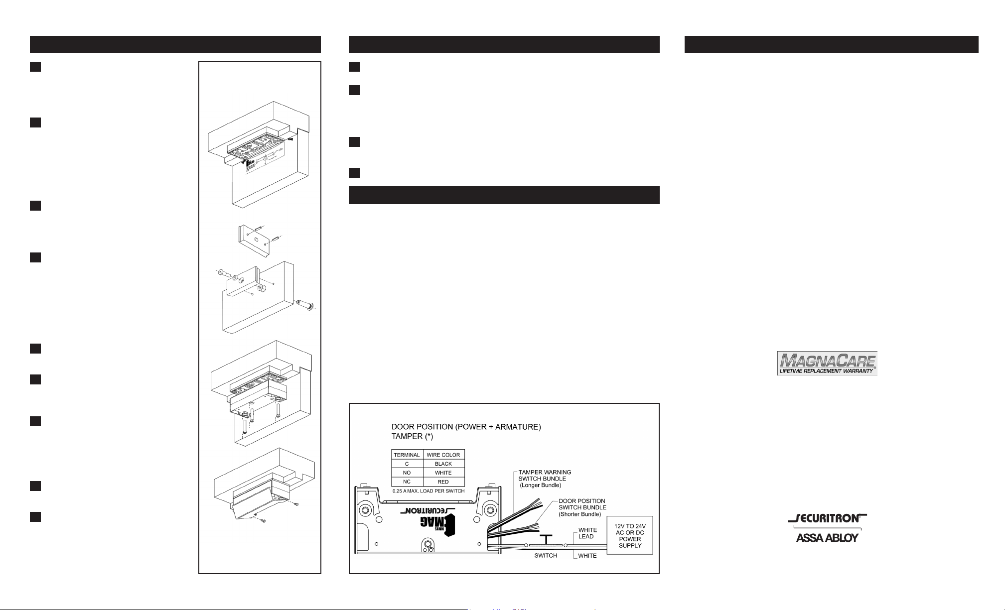
Door Prep/Armature Mounting
With the door closed, align the
1
armature template between the
tabs on the mounting plate and
mark the three holes.
For Metal Doors: Locate the middle
2
marked hole. Center punch and drill
a 3/8” hole through the door. Enlarge
hole from the outside face to 1/2”.
For Wood doors: Drill a 1/2” hole
through the door.
Center punch and drill two 1/4”
3
(x 1/2” deep min.) holes in the
inside face of the door for the
two anti-rotation pins.
Lay the armature on a clean,
4
at surface and insert the 3/16”
x 3/4” roll pins provided into
the two holes on the back of
the armature. Gently tap the
roll pins with a small hammer
or mallet until they are rmly
seated.
Insert sex bolt from the outside
5
face of the door.
Place the O-ring on the shoulder
6
screw and insert through the
armature.
MM15 Magnalock Mounting
Remove the cover from the MM15.
1
Secure the MM15 to the mounting plate with the three 1/4-20 x
2
1-3/4” cap screws, feeding the wiring through the ller plate and
header. If using conduit option, the wires exit through the side of
the MM15 Maglock.
Replace the MM15 cover by aligning it with the tapped holes and
3
pushing it up until the lip snaps into place.
Fasten cover with the two #6-32x1/4” at head screws.
4
Electrical Installation and Wiring
The standard MM15 Maglock unit will operate on 12 to 24 VAC or VDC
and is not polarity sensitive.
18-gauge (minimum) wire should be used to minimize voltage drop.
Connection of a reverse diode or M.O.V. in parallel with the MM15’s
power input is not necessary. The MM15’s internal circuitry suppresses
the inductive kickback often seen with electromagnetic coil locks.
Monitor Switches
MM15 Maglocks ordered with the monitoring option are tted with
two SPDT microswitches that provide the following indications:
Door Position – Armature closed against the MM15 Maglock.
(*) Tamper Warning – Indicates that the MM15 is being
forced enough to activate the locking arms. When
locking arms are activated, tamper switch changes state.
Component List and Identication
QTY COMPONENT
(1) MM15 Maglock with Cover
(1) Mounting Plate
(1) Armature
(1) Armature Template
(2) Roll Pins - 3/16” x 3/4”
(1) Sex Bolt
(1) Shoulder Screw
(1) Rubber O-Ring
(3) Spring Washers
(4) Blind Nuts
(4) Pan Head Screws - 1/4-20x1”
(3) Socket Head Cap Screws
1/4-20x1-3/4”
(1) Hex Wrench
(2) Threadlock
(8) Wire Nuts
This product must be installed according
to all applicable building and life safety codes.
MAGNACARE LIFETIME REPLACEMENT WARRANTY
Place the spring washer(s) on
7
the shoulder screw to provide
the spacing required for the
armature to fully contact the
MM15.
Locate the armature with roll
8
pins onto the door.
Fasten shoulder screw to sex bolt
9
with a 3/16” hex wrench using
thread lock. Additional spring
washers may be necessary to
ensure that the armature oats
properly, but is not loose.
For warranty information visit:
www.securitron.com/en/site/securitron/about
MagnaCare-warranty/
SECURITRON MAGNALOCK CORP.
1-800-MAGLOCK
www.securitron.com
Page 2
Installation Instructions
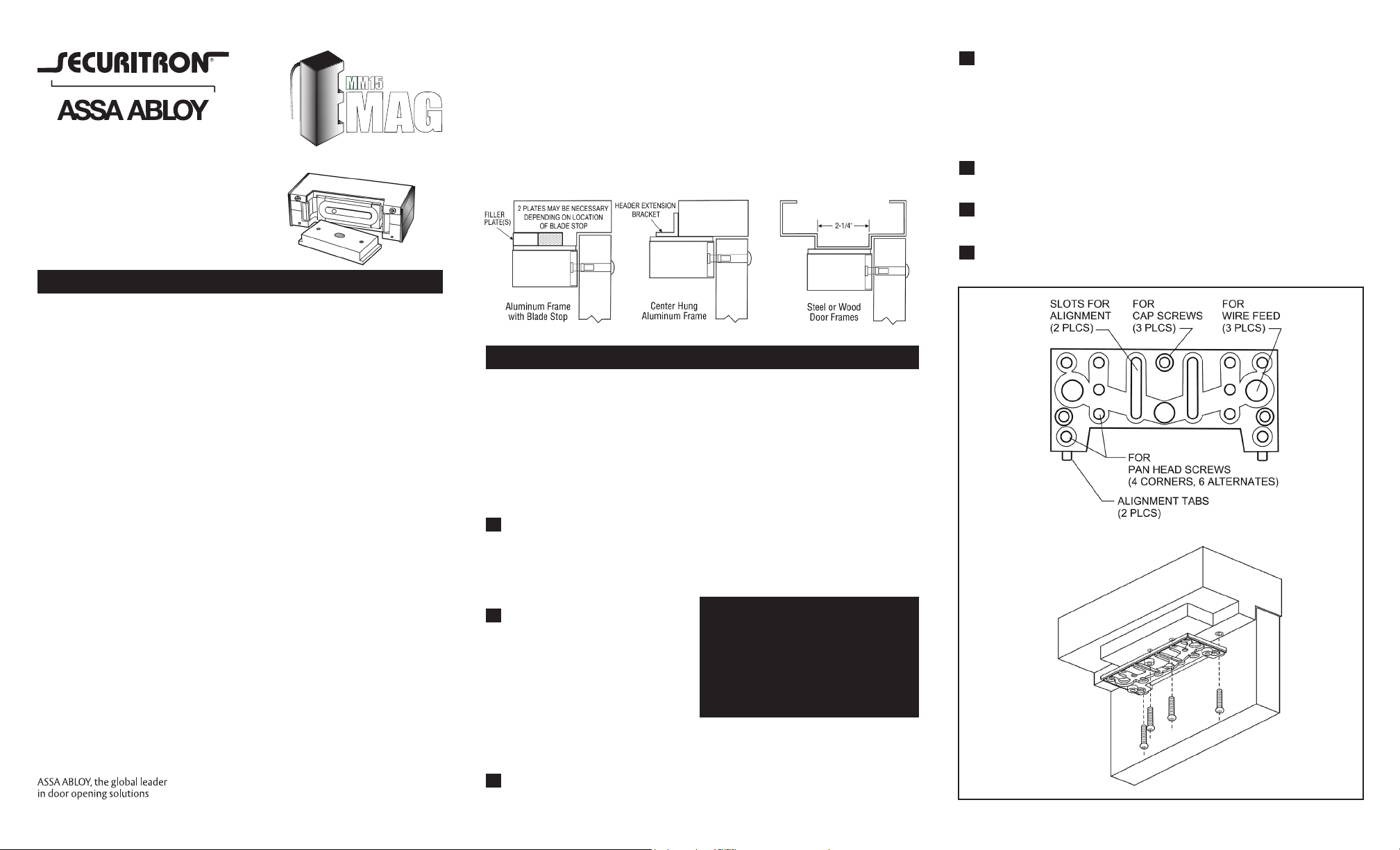
Aluminum Door Systems:
Door frames with blade-type/narrow stops will require a ller plate. The
height of the stop is needed when ordering ller plates. Narrow frame
sections and centerhung doors require an angle bracket to support the
MM15.
Steel/Wood Door Frames:
For adequate support, a door with stops less than 2-1/4” wide should
be tted with a ller plate.
Page 1
In each mounting location, drill a 3/8” hole in the header and
4
install Blind Nuts, using the supplied hex wrench. Refer to
Blind Nut installation instructions in the mounting hardware
kit.
Note: In reinforced steel frames, it is permissible to drill
If not using conduit, drill one 9/16” (or 3/8” minimum) wire feed
5
hole in the door frame.
This product must be installed
according to all applicable building
and life safety codes.
MM15 Maglock Mounting Basics
Maglocks are used in a wide variety of applications; therefore it is
important to inspect the door frame area for proper placement of the
device. For optimum performance, the mounting surface should be
strong enough so that the full holding strength of the MM15 is utilized.
Different door frame congurations require specic fastening methods.
A ller plate or header extension bracket is often needed to properly
support the MM15. Steel blind nuts are the preferred method of
mounting in steel and aluminum frame construction, although drilling
and tapping is acceptable in reinforced hollow metal frames. A
minimum of four blind nuts are required to provide adequate strength.
For standard applications, the electro-magnet should be mounted
rmly to the underside of the header in the corner farthest away
from the hinges. The armature mounts to the face of the door with
special hardware, which allows for proper oating action. This action
is very important in assuring total mating of the armature with the
face of the electro-magnet.
Handle all electro-magnetic locks and armature plates carefully. Any
damage to the mating surfaces may signicantly reduce holding
efciency.
Site Survey
When used with frames with an integral jamb or with narrow frames
that do not fully support the MM15, use the appropriate ller plate or
header extension bracket to adequately support the base of the MM15.
A Z-Bracket is required when installing the MM15 on in-swinging
door. The Z-Bracket installation instructions are included in the MM15
Z-Bracket Kit.
Frame Preparation
Frames need to be marked for drilling using the mounting plate as a
template. Doors need to be marked for drilling using the plastic armature
template. All measurements should be made with the door in the fully
closed position.
To ensure the proper location of the maglock and armature for successful
mounting, adjust the MM15 to clear other hardware or door and frame
features that would interfere with the installation.
Place the ller plate on the
1
mounting plate. The ller
plate should be aligned with
the back edge and sides of
the mounting plate.
With the door fully closed,
2
locate the mounting plate and
the ller plate to the header
with the alignment tabs resting
on the face of the door. Using
the predrilled holes in the center
of the ller plate and two of the
furthest forward corner holes,
mark four holes for mounting
the two plates to the header.
Installation shown with use
of ller plate. Mounting will
differ for other applications.
WARNING:
This device is capable of holding
4000 lbs. It is the responsibility of
the installer to provide adequate
strength to prevent screw pullout
or collapse of the frame or header.
Replace the mounting plate and ller plate, then secure with pan
6
head screws using thread lock.
Additional screws may be installed for added stability and strength
6
in any of the alternate holes.
If not using conduit, mark one
3
of the wire feed hole locations.
MM15-01 Rev. C
 Loading...