

Page 1
Securitron Magnalock Corp. www.securitron.com ASSA ABLOY, the global leader
Tel 800.624.5625 techsupport@securitron.com
in door opening solutions
INSTALLATION AND OPERATING INSTRUCTIONS
FOR
Magnetic Cabinet Lock MCL-24
1. INTRODUCTION
Securitron’s model MCL-24 is a Magnetic Cabinet Lock designed to work with swing or sliding
cabinets and drawers. The assembly consists of the Magnalock Body, Universal Mounting Bracket
and Armature as well as the installation hardware. The MCL-24 Universal Mounting Bracket
allows the Magnalock Body or the Armature to be mounted in a wide variety of configurations
making it a snap to install just about anywhere.
2. SPECIFICATIONS
Holding Force: 200Lbs
(90 Kg)
Dimensions: 4.6” X .75” X 1.14”
(117 X 19 X 29mm)
Voltage: 24 Volts DC Only
Current Requirement: 62mA
Power Consumption: 1.5 Watts
3. PRODUCT OVERVIEW
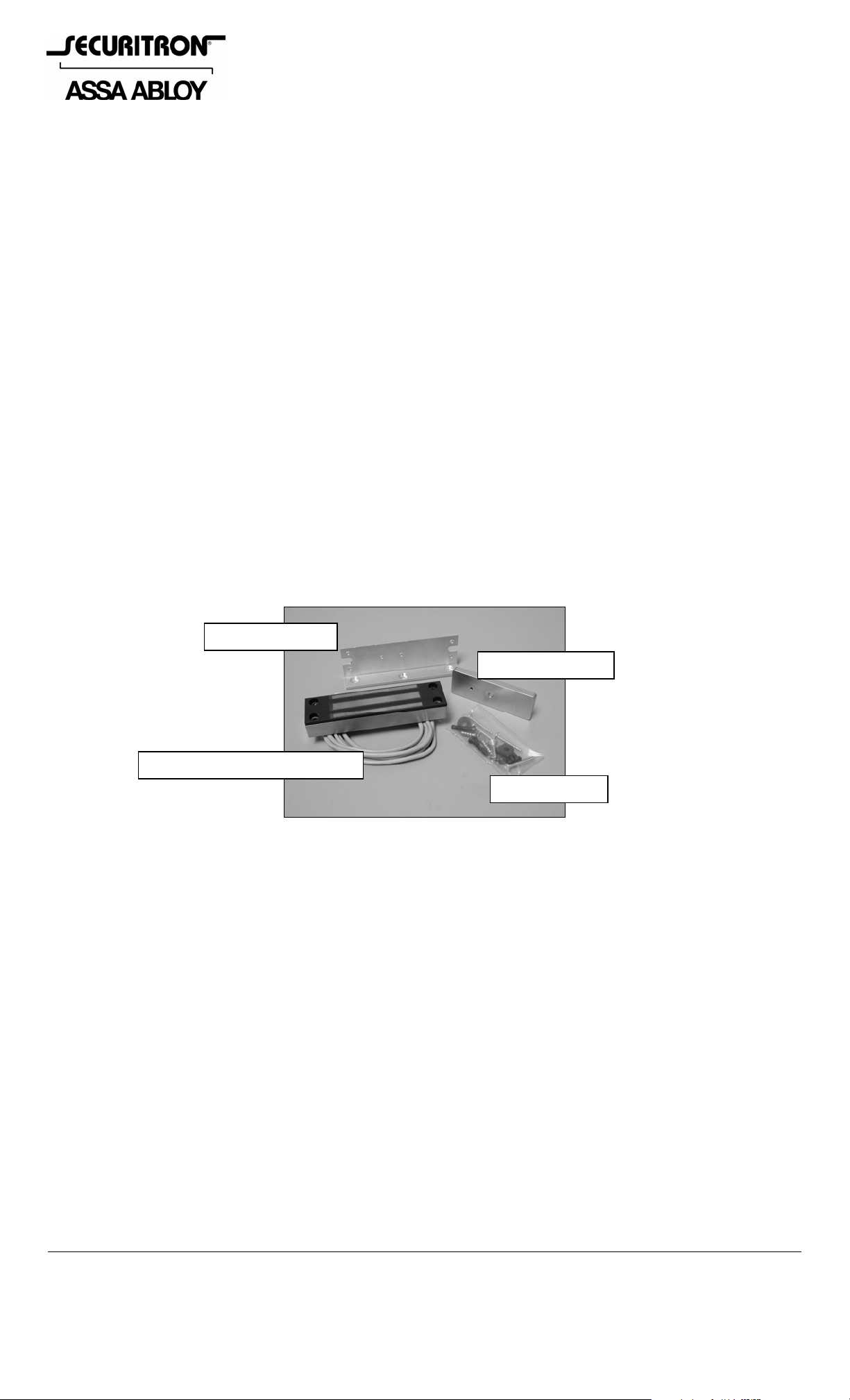
Upon unpacking this product, an inventory should be made to ensure that all the required
components and hardware have been included. Along with these Instructions and the
Installation Template this product should include the following items:
Universal Bracket
Strike Plate (MCL)
Magnetic Cabinet Lock (MCL-24)
Hardware Pack
(Note that a complete list of all included parts is provided in Section 5.2 of these instructions).
4. RECOMMENDED TOOLS
Drill Motor
Drill Bits:
13/64”, 1/8”, 3/32” and 1/4” (Optional)
Phillips and Standard Screw Driver
Measuring Tool (ruler or tape measure)
Wire Stripper
Crimping Tool
Digital or Analog Volt Ohm Meter (for diagnostics)
5/64” Hex (Allen) Wrench
5. INSTALLATION INSTRUCTIONS
5.1. Pre-Installation Survey/Assessment
Due to the wide variety of mounting configurations available for this product, it is strongly
recommended that an initial survey and assessment be made of the physical area to which
the Magnalock will be installed. A determination of the optimal method o f mounting should b e
made prior to installation with considerations made to the following:
© Copyright, 2011, all rights reserved PN# 500-19100
Page 1 Rev. C, 04/11
Page 2
A. Physical strength of mounting area. The structural integrity of mounting surface s must be
strong enough to meet or exceed the holding force of the Magnalock.
B. Protection of the lock from external attack. The Magnalock and the wiring must be
protected to a reasonable degree from potential damage due to intruders or vandals.
C. Convenience and accessibility of area to be protected. The Magnalock assembly sh ould be
installed in a location that will not hinder or create a potential safety hazard to auth orized
personnel routinely accessing the protected area.
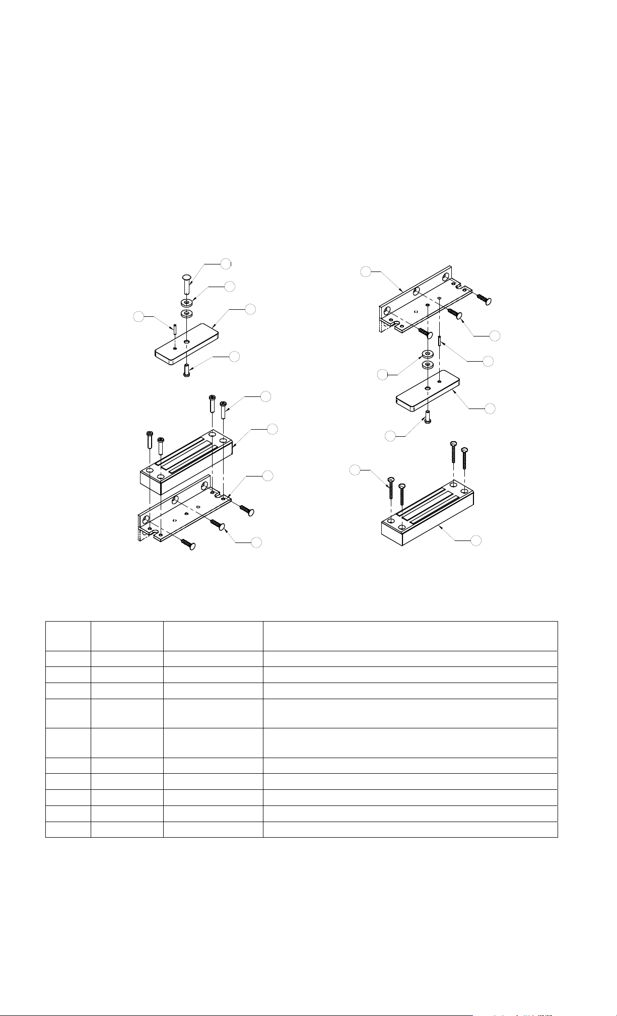
5.2. Magnalock Body and Strike Plate Installation
The exploded illustration below displays two mounting configurations available using the
hardware provided:
7
5
6
3
4
9
1
2
8
2
8
6
5
3
4
10
1
Mounting LOCK BODY with BRACKET
Mounting STRIKE PLATE with BRACKET
ITEM QTY
PART
NUMBER
NOMENCLATURE/DESCRIPTION
1 1 772-MCL-24 Magnalock Body
2 1 390-17110 Universal Bracket
3 1 380-20000 Strike Plate (MCL)
4 1 300-11620
5 2 310-11210
#8-32 UNC X 1/2” Long Low Profile Socket Head
Cap Screw
1/2” O.D. X 3/16” I.D. X .093” Neoprene Rubber
Washer
6 1 330-10670 3/32” O.D. X 1/2” Long Roll Pin
7 1 330-12170 Sex Bolt (#8-32 X 7/8” Binder Head)
8 3 300-11790 #10 X 3/4” Long (Phillips) Flat Head Screw
9 4 300-11645 #8-32 UNC X 3/4” Long Socket Head Cap Screw
10 4 300-11710 #6 X 1” Long (Phillips) Pan Head Screw
PN# 500-19100
Page 2 Rev. C, 04/11
Page 3
5.2.1. Magnalock Body to Universal Bracket Installation
This section will provide step-by-step installation instructions for the option of mounting
the Magnalock Body using the Universal Bracket provided and the Strike Plate th rough a
door/access panel.
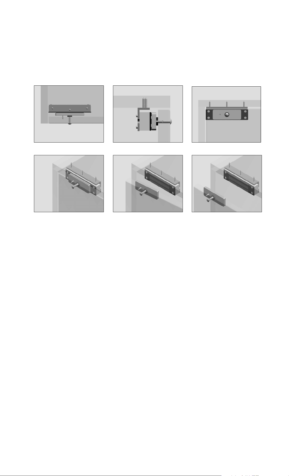
The following illustrations display installation of the Magnalock Body t o Universal Bracket
configuration and show examples of some typical Swinging Door and Pull Out Drawer
applications:
Top View Left View Front View
Closed Open (Swing Out) Open (Pull Out)
Cabinet Door Drawer
Using Installation Template (Part #500-20250), layout and prepare mounting surfaces
(See Option #1 of Template).
Strike Plate:
1. Drill 13/64” diameter hole through Door/Panel for Sex Bolt.
2. Drill 1/8” diameter hole x .300” deep for Strike Plate Guide Pin.
3. Insert Strike Plate Guide (Roll) Pin (Item #6) into hole in Strike Plate (Item #3)
and gently tap Pin into hole until it is seated firmly in place.
4. Insert Sex Bolt (Item #7) through Door.
5. Install the two (2) Rubber Washers (Item #5) over the end of the Sex Bolt.
6. Set Strike Plate into place, aligning its center hole with the Sex Bolt and the Guide
Pin into the 1/8” hole previously drilled in Step 2.
7. Insert #8-32 UNC x 1/2” Long Low Profile Socket Head Cap Screw (Item #4)
through Strike Plate and into the end of the Sex Bolt. Tighten the assembly using a
5/64” Hex (Allen) Wrench.
Magnalock Body:
1. Drill three (3) 1/8” diameter x 1/2” deep pilot holes into cabinet mounting surface.
2. Install Universal Bracket (Item #2) using three (3) #10 x 3/4” Long Flat Head
Wood Screws (Item #8). Tighten the screws firmly using a Phillips Head
Screwdriver.
3. Orient Magnalock Body onto Universal Bracket with Power Cable to the desired end
and mount Lock to Bracket using the four (4) #8-32 UNC x 3/4” Long S ocket Head
Cap Screws (Item #9). Tighten the assembly using a 1/8” Hex (Allen) Wrench.
4. Run Power Cable to terminal connection as required.
PN# 500-19100
Page 3 Rev. C, 04/11
Page 4

5.2.2. Strike Plate to Universal Bracket Installation
This section will provide step-by-step installation instructions for the option of mounting
the Strike Plate using the Universal Bracket provided and the Magnalock Body directly to
an opposing mo unting surface.
The following illustrations display installation of the Strike Plate to Universal Bracket
configuration and show an example of a typical Sliding Door application:
Top View (Closed) Front View (Closed)
View from Inside (Closed) View from Inside (Open)
Using Installation Template (Part #500-20250), layout and prepare mounting surfaces
(See Option #2 of Template).
Strike Plate:
1. Drill three (3) 1/8” diameter x 1/2” deep pilot holes into mounting surface.
2. Install Universal Bracket (Item #2) using three (3) #10 x 3/4” Long Flat Head
Wood Screws (Item #8). Tighten the screws firmly using a Phillips Head
Screwdriver.
3. Insert Strike Plate Guide (Roll) Pin (Item #6) into hole in Strike Plate (Item #3)
and gently tap Pin into hole until it is seated firmly in place.
4. Set Strike Plate into place, aligning its center hole with the center (threaded) hole
of the Universal Bracket and the Guide Pin into the 1/8” hole in the Bracket.
5. Install the two (2) Rubber Washers (Item #5) between Strike Plate and Universal
Bracket.
6. Insert #8-32 UNC x 1/2” Long Low Profile Socket Head Cap Screw (Item #4)
through Strike Plate and into the threaded center hole of the Universal Bracket.
Tighten the assembly using a 5/64” Hex (Allen) Wrench.
Magnalock Body:
1. Drill four (4) 3/32” diameter x 7/16” deep pilot holes into cabinet mounting surface.
2. Drill 1/4” diameter hole through - or rout a small channel in the mounting surface
to provide clearance for Magnalock Body Power Cable.
3. Insert end of Power Cable through clearance hole and feed through until Magnalock
Body sits flush against mounting surface.
PN# 500-19100
Page 4 Rev. C, 04/11
Page 5

4. Install Magnalock Body using four (4) #6 x 1” Long Pan Head Wood Screws (Item
#10). Tighten the screws firmly using a Phillips Head Screwdriver.
5. Run Power Cable to terminal connection as required.
6. OPERATIONAL INSTRUCTIONS
The Securitron Model MCL-24 is a Fail Safe locking device (p ower to lock). To power the MCL-24
you simply apply positive voltage DC to the red wire of the Magnalock through a normally closed
control switch. The black wire of the Magnalock should return directly to the negative DC.
Example
SPDT
CONTROL
POWER SUPPLY
120
VAC
+
IN
VDC
-
OUT
SWITCH
NC
C
NO
RED
BLK
MCL-24
+
-
6.1. WIRE GAUGE SIZING
If the power supply is distant from the lock, voltage will b e lost (dropped) in the connecting
wires so that the Magnalock will not receive full voltage. The following chart shows the
minimum wire gauge that will hold voltage drop to an acceptable 5% for different lock to
power supply distances. Proper use of the chart assumes a dedicated pair o f wires to power
each Magnalock (no common negative). Note that a Magnalock operating on 24 volts is a
much better choice for long wire runs as it has 4 tim es the resi stance of a 12 volt in stall ation.
Also note that the correct calculation of wire sizing is a very important issue as the installer i s
responsible to insure that adequate voltage is supplied to any load. In multiple device
installations, the calculation can become quite complex so refer to Section 9 Appendix A for a
more complete discussion.
Distance Gauge 12V Gauge 24V
Distance Gauge 12V Gauge 24V
80 FT 20 GA 24 GA 800 FT 10 GA 16 GA
200 FT 17 GA 22 GA 1500 FT 8 GA 14 GA
400 FT 14 GA 20 GA 3000 FT N/A 12 GA
7. MAINTENANCE
Maintenance for MCL-24 is very simple. Once every six months we recommend taking a clean
cloth and rubbing alcohol or a non-abrasive cleaner and wiping down the face of the Magnalock
and the Armature. This prevents a build up of foreign materials from the air making the
Magnalock stick.
8. TROUBLESHOOTING
PROBLEM: No magnetic attraction between magnet and strike plate.
First be sure the Magnalock is being correctly powered with DC voltage. This includes
connecting the power wires with correct polarity. Positive must go to red and negative to
black. If the magnet body is wired in reverse polarity, it will not be damaged, but it will not
operate. If the unit continues to appear dead, it must be electrically checked with an
Ammeter. It must be powered with the correct input voltage and checked to see if it draws
the specified current. If the unit meters correctly, it is putting out the correct magnetic field
and the problem must lie in the mounting of the strike.
PROBLEM: The lock does not release.
When power is removed from it, the Magnalock must release. Therefore the complaint of
"lock will not release" is either mechanical bonding via vandalism or a failure to completely
release power. By mechanical bonding, we simply mean that glue has been applied between
the armature and magnet as a prank. Failure to completely release power is generally a
wiring integrity problem. What happens is that an upstream switch removes powe r from the
wires going to the Magnalock, but through an installation error, the wires have their
insulation abraded between the switch and lock so that partial or full p ower can leak in from
another Magnalock or other DC device with similarly abraded wiring. This is most likely to
PN# 500-19100
Page 5 Rev. C, 04/11
Page 6

occur at the point where the wire cable leaves the Magnalock case and enters the door
frame. Another area is via an improper splice on wiring in conduit. Either a metal door frame
or the metal conduit is capable of leaking power between multiple devices with abraded
wires, thereby bypassing switches. A good way to check this electrically (as opposed to
visually removing and inspecting the wires) is to use a meter and check for leakage between
the power supply positive or negative and the door frame and conduit. Magnalocks should be
powered by isolated DC voltage without any earth ground reference to positive or negative.
PROBLEM: The lock rusts.
Both the magnet core and armature are plated and sealed following a military sp ecification. If
rusting appears, the most common cause is that improper cleaning (with steel wool for
instance) has occurred and this has stripped off the relatively soft plating. Once the plating
has been removed, it cannot be restored in the field, so the lock will have to be periodically
cleaned and coated with oil or other rust inhibitor. A rusty Magnalock will still functi on but at
reduced holding force. If the product is installed in a heavily corrosi ve atmosphere, such as
near the ocean, it will eventually rust even with non-abrasive cleaning. The only an swer then
becomes continued periodic removal of the rust.
9. APPENDICES
A. CALCULATING WIRE GAUGE SIZING
The general practice of wire sizing in a DC circuit is to avoid causing voltage drops in
connecting wires that reduce the voltage available to operate the device . As Magnalocks are
very low power devices, they can be operated long distances from their power source. For
any job that includes long wire runs, the installer must be able to calculate the correct gauge
of wire to avoid excessive voltage drops.
This is done by taking the current draw of the lock and multiplying by the resistance of the
wire I x R = Voltage drop (i.e. 0.100A x 10.1 Ohms = 1.01 Volts dropped across the wire).
For all intents and purposes it can be said that a 5% drop in voltage is acceptable so if this
were a 24 Volt system (24 Volts x .05 = 1.2 Volts) a 1.01 Volt drop would be within
tolerance.
To calculate the wire resistance, you need to know t he distan ce from the p ower supply to the
Magnalock and the gauge (thickness) of the wire. The following chart sh ows wire resistance
per 1000 ft (305 meters):
Wire Gauge Resistance/1,000 ft
8 Gauge .6 Ohms 16 Gauge 4.1 Ohms
10 Gauge 1.0 Ohms 18 Gauge 6.4 Ohms
12 Gauge 1.6 Ohms 20 Gauge 10.1 Ohms
14 Gauge 2.5 Ohms 22 Gauge 16.0 Ohms
Wire Gauge Resistance/1,000 ft
PN# 500-19100
Page 6 Rev. C, 04/11
Page 7

B. Preparation for Swinging Door and Pull Out Drawer Installations:
C
Ref. CL
1.875
.850
L
1.875
.750
Ref. CL
C
L
NOT TO SCALE - DIMENSIONS IN INCHES
VIEW OF LOCK BODY INSTALLATION
C
L
.50
1.875
.950
Drill .125 Diameter
Hole .300 Deep
VIEW OF STRIKE INSTALLATION
FROM D OOR OF CABI N ET
FROM TOP OF CABINET
1.875
.150
.203 Diameter
Hole Thru
C
L
For Sex Bolt
PN# 500-19100
Page 7 Rev. C, 04/11
Page 8

C. Preparation for Sliding Door Installation
2.60
Ref CL
.60
2.00
L
2.00
.725
1.875
CC
L
3.750
1.875
VIEW OF LOCK BODY AND STRIKE
1.60
1.60
.120
NOT TO SCALE - DIMENSIONS I N INCHES
VIEW OF LOCK BODY AND STRIKE
FROM TOP OF CABINET
.120
FROM DOOR OF CABINET
.70
.50
10. MAGNACARE
For warranty information visit www.securitron.com/en/site/securitron/About/MagnaCare-Warranty/
LIFETIME REPLACEMENT WARRANTY
PN# 500-19100
Page 8 Rev. C, 04/11
 Loading...