

Page 1
Securitron Magnalock Corp. www.securitron.com ASSA ABLOY, the global leader
Tel 800.624.5625 techsupport@securitron.com
in door opening solutions
CCB-8-12 / CCB-8-24 SLAVE BOARD
INSTALLATION INSTRUCTIONS
1. DESCRIPTION
The CCB-8-12/24 allows the addition of eight individually Polyswitched outputs to an existing
power supply. The power supply’s total current capacity remains the same. The CCB-8-12/24
may be installed into the existing power supply enclosure via the provided snap-trak. The CCB8-12/24 is not compatible with the Securitron 1 amp power supply.
SLAVE BOARD
R1
R2
R3
R4
R5
R6
R7
R8
P1
P2
P3
P4
P5
P6
- +
S
-
S
+
BLACK WIRES
MASTER BOARD
RED WIRES
R1
R2
R3
R4
R5
R6
R7
R8
P1
P2
P3
P4
P5
P6
- +
S
-
S
+
DC
FUSE
AC
FUSE
H
N
G
P7
P8
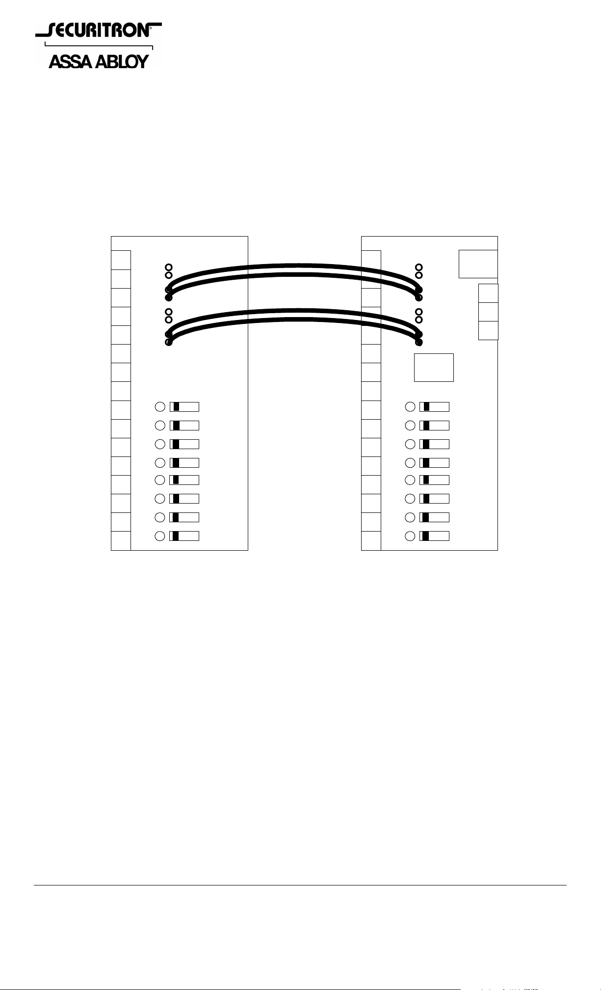
Figure 1
2. INSTALLATION & WIRING
It is recommended that the CCB-8-12/24 be mounted below the main distribution board. The
CCB-8-12/24 comes standard with four 8” flying leads. Prior to installation, ensure that you
have the correct version of the CCB board for the power supply as they a re available in 12 VDC
or 24 VDC.
The CCB board has 4 wires (2 red wires and 2 black wires) which must b e soldered to the main
distribution board. Remove AC power and disconnect the battery leads from the b attery before
soldering. The 2 black wires should be soldered to the main board’s “S-” solder p oints. The 2
red wires should be soldered to the main board’s “S+” solder points (as shown in Figure 1).
Note: Any modification to the Power Supply including the addition of the CCB will void
the UL Certification.
P7
P8
© Copyright, 2011, all rights reserved PN# 500-10350
Page 1 Rev. B, 07/11
 Loading...