

Page 1
Securitron Magnalock Corp. www.securitron.com ASSA ABLOY, the global leader
Tel 800.624.5625 techsupport@securitron.com
in door opening solutions
SOLAR POWER SUPPLY MODELS BPSS-10 AND BPSS-20
INSTALLATION AND OPERATING INSTRUCTIONS
1. INTRODUCTION
The Solar Power Supply models BPSS-10 and BPSS-20 combine Securitron’s renowned power
supply technology with solar capability for access control in remote/iso lated locations. The BPSS
controller, contained in a NEMA-3R rated cabinet, is specifically designed for outdoor applications
and is provided with its own separately mounted, adjustable solar PV array power panel and
battery backup. Each unit operates at 12 VDC and is intended to operate an access control
device (e.g. DK-26 keypad or card access system) and fail secure intermittent lock (e.g. GL-1
gate lock or electric strike). This manual is intended to provide the installation, electrical
requirements and functional options required to successfully install a BPSS unit.
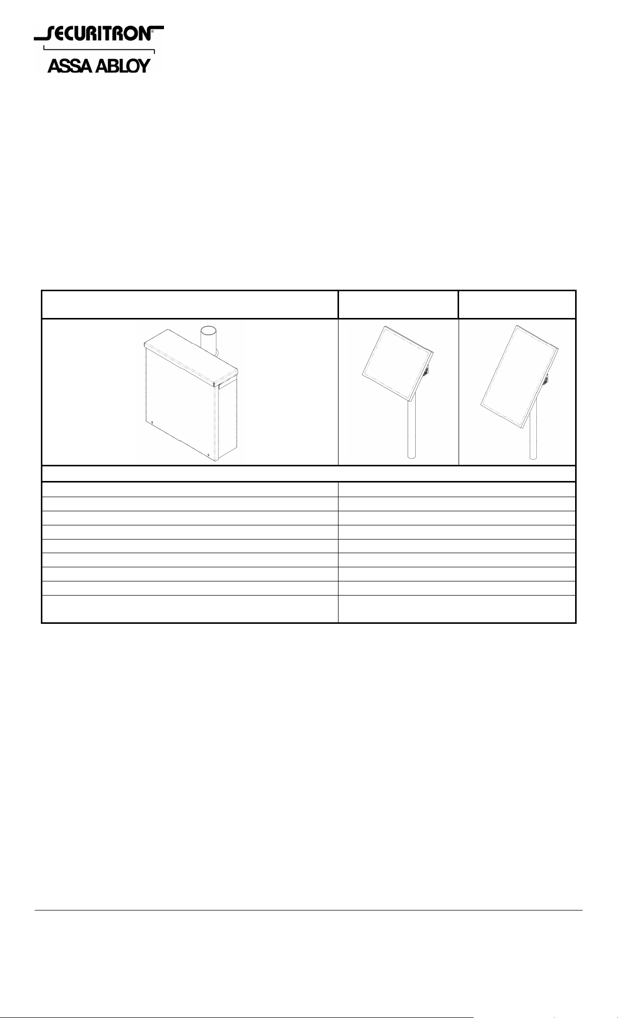
2. SPECIFICATIONS
Power Supply Cabinet
MODEL BPSS-10/BPSS-20 Power Supply Specifications
Use/Environment
Cabinet Weight (without batteries)
Cabinet Dimensions: Length
Height
Depth
Voltage
*Maximum Output Current – Continuous
*Maximum Output Current – While Operating Lock
Operating Temperature Range
(with batteries)
10 Watt
PV Array Panel
Outdoor (NEMA-3R)
14 Lbs [6.4 kg]
12.8” [325mm]
12.2” [310mm]
4.7” [119mm]
11.5-14.1 Volts DC
*Up to 125mA
*Up to 425mA
-4° to +113° F
[-20° to +45° C]
20 Watt
PV Array Panel
*Number of daily lock operations may vary due to solar activity and system current draw.
3. RECOMMENDED TOOLS
Hammer
Center Punch
Power Drill
Drill bits
Wrenches
Pliers, vise grip
Screwdrivers: Phillips & 1/8”
Flat Blade
Fish Tape or Lead Wire
Wire Strippers/Cutter
Multimeter
4. INSTALLATION INSTRUCTIONS
It is recommended that a site survey be performed to determine the mou nting location prior to
installation. The following should be considered:
The unit should be placed in a position without obstruction of the sun which will allow
optimum use of the PV array panel.
Physical strength of mounting areas should provide adequate support of the installed unit.
Adequate space should be provided for ventilation. Ensure that there is at least 2” of
unobstructed space provided around the four sides of the enclosure.
Ensure wiring can be routed to protect from damage due to intrusion or vandalism. (The
enclosure is provided with knock-outs for conduit connections).
© Copyright, 2011, all rights reserved PN# 500-22125
Page 1 Rev. D, 08/11
Page 2
4.1 Physical Installation
The BPSS controller is rated for outdoor use and is specifically designed to be affixed to a pole or
post up to 2” O.D. (outer diameter) using the included hardware. Use short U-bolt in lower
mounting holes to allow room for battery. A bracket kit accessory package for larger
diameters is also available (see Section 6). A drop-in hasp for a padlock (not included) has
been furnished to secure the cabinet cover.
The BPSS controller is furnished with a pole/post mounted adjustable PV array panel to be
mounted above the BPSS controller cabinet. Please see Section 5 for PV array panel installation
and adjustment information.
4.2 Electrical Installation
4.2.1 Power Controller Characteristics
Securitron's BPSS utilizes a sophisticated power controller which incorporates advanced
technology and series switching, pulse width modulation (PWM) charging. The battery charging
process has been optimized for longer battery life and improved system performance. Many
specifications of the controller are unique. Although the controller is very simple to use, please
take the time to read this manual and become familiar with it s functions. This will h elp to make
full use of the many advantages the controller can provide to the PV system being used.
4.2.2 Controller Safety
SAVE THESE INSTRUCTIONS! - This manual contains important instructions that should be
followed during installation and maintenance of the controller.
WARNING! - Be very careful when working with batteries. Lead acid batteries can generate
explosive gases, and short circuits can draw thousands of am ps from the battery. Read and
follow all instructions provided with the battery.
Do not exceed the voltage or current ratings of the controller. Use only with a 12 Volt
battery rated between 5Ah and 20Ah.
DO NOT short circuit the PV array or load while connected to the controller. This will
DAMAGE the controller.
The controller should be protected from direct sunlight. Ensure adequate space for air flow
around the controller.
The negative system conductor should be properly grounded. All grounding and wiring
should comply with local codes.
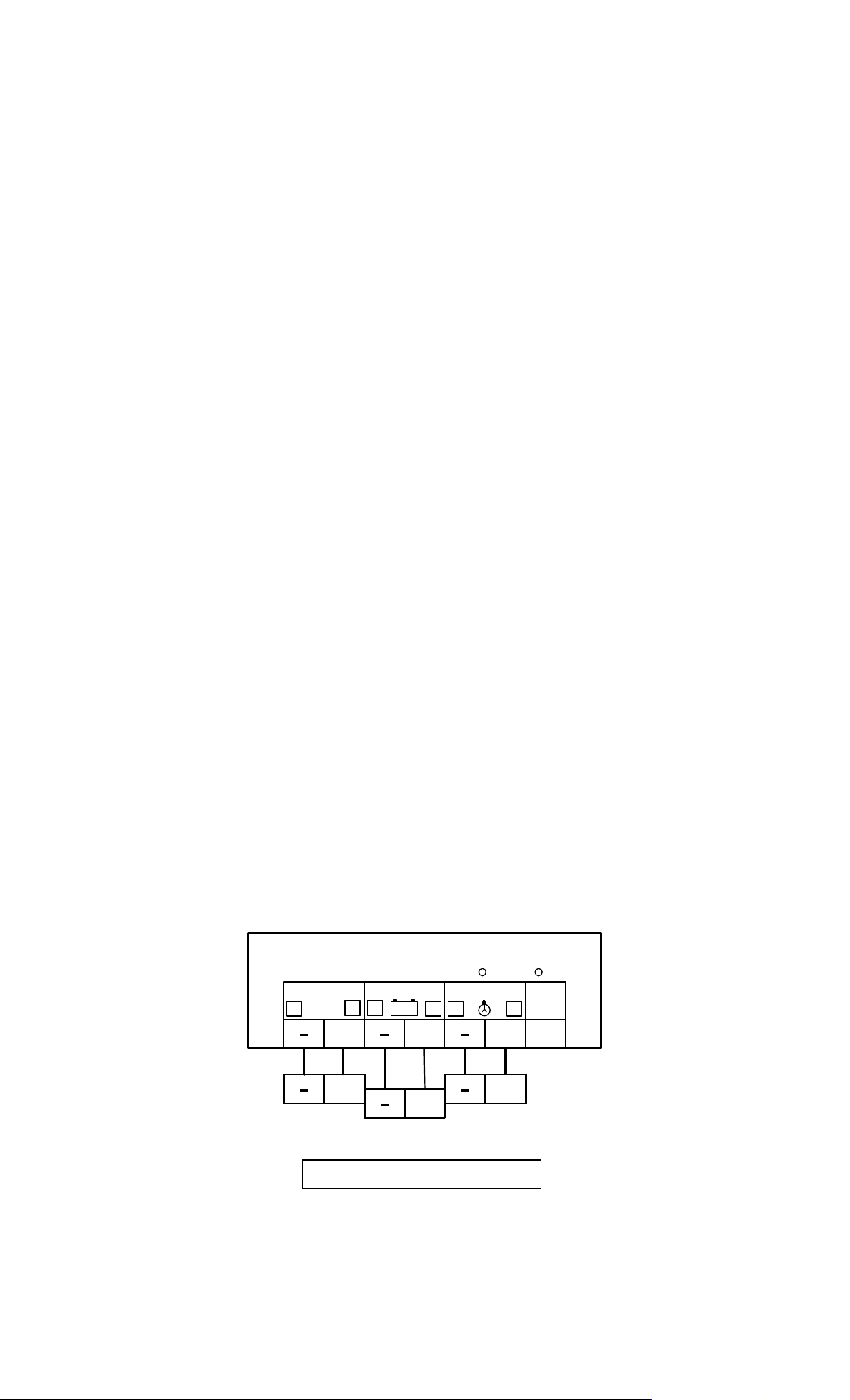
4.2.3 Controller Wiring
The six (6) system connections to the controller terminals are numbered “1” to “6” on the label
as shown in Figure 1. It is recommended that the connections be made in order from 1
to 6.
1. Connect the BATTERY first. Use care that bare wires do not touch the metal case of
the controller.
2. Connect the SOLAR (PV array) next. The green LED indicator will light if sunlight is
present.
3. Connect the LOAD last. This model includes a low voltage disconnect (LVD). If the red
LED indicator lights, the battery capacity is low and should be charged before completin g
the system installation.
Power Controller
PN# 500-22125
Page 2 Rev. D, 08/11
Figure 1
Page 3

Notes:
The controller is shipped with a jumper installed. This sets the controller for charging
SEALED batteries. If a FLOODED battery is being used, simply remove the jumper to
optimize the battery charging for a flooded battery. If the jumper is connected again, th e
charging will return to the set-points for a sealed battery.
For safety and the most effective lightning protection, the negative conductor of the PV
system should be properly grounded. The controller connects the PV-negative, Battery
negative and Load- negative internally per UL recommendations. No switching is done in
the negative current path.
4.2.4 Operating Characteristics
4.2.4.1 Polarity Protection
The controller is generally protected from reversed connections, but the system operator and
other equipment will be at risk when polarities (+ and –) are reversed. Carefully check before
making each connection to ensure that the polarity is correct.
4.2.4.2 LED Indicators
Green LED:
The green LED indicator located on the power controller is lit whenever sunlight is available for
battery charging. The green LED will turn off at night. Because the controller uses a PWM
constant voltage charging process, there is usually some amount of energy going into the
battery at all times. Although the charging current falls to very low levels when the battery
reaches full charge, the green LED will continue to stay ON (during the daytime). This is to
indicate that the controller is working and that energy is available from the PV array for
charging.
Red LED:
The controller includes an automatic load disconnect (LVD) feature along with a red LED
indicator. Whenever the battery charge state falls below the LVD set-point, the load will be
disconnected and the red LED will light. This indicates that the controller has di sconnected the
load to protect the battery from further discharge and possible damage. After some period of
recharging the battery, such that it recovers to approximately 40 to 50 percent of its rated
capacity, the load will automatically be reconnected and the red LED will turn off.
4.2.4.3 Controller Features and Functions
Low Voltage Disconnect (LVD):
If the battery falls below 11.5 volts, the load is disconnecte d from the battery to protect against
harmful deep discharges. A 2-second delay prevents load disconnects from transients. The load
is automatically reconnected when the battery voltage recovers to 12.6 volts.
Battery Disconnect:
If the battery is disconnected during the daytime, the PV array will continue to provide power to
the controller. The controller will immediately go into PWM and provide power at a constant
voltage to the load. This may continue as long as power is available from the PV array.
Auxiliary Generators:
Engine generators and other sources of power may be connected directly to the battery for
charging. It is not necessary to disconnect the controller from the battery. However, do not use
the controller to regulate these other generators.
Reverse Current:
The controller prevents the battery from discharging through the PV array at night. There is no
need to install a blocking diode for this purpose.
Noise:
The controller circuit minimizes switching noise and filters all noise output to extremely low
levels when the system is properly grounded. If noise is present in a telecom loa d, it is most
likely due to a grounding problem in the system.
PN# 500-22125
Page 3 Rev. D, 08/11
Page 4

5. PV ARRAY PANEL INSTALLATION
5.1 INSTALLING THE PANEL
The following exploded illustration Figure 2 shows the included hardware required to properly
mount the array panel to a vertical pole. (10 Watt PV array panel shown).
1/4-20 U-BOLT
6X #10 PLAIN
6X 10-32 X 7/16
LONG PPH SCREW
FLAT WASHER
2X #10 SPLIT
LOCK WASHER
PV ARRAY
PANEL
PANEL MOUNTING
CROSS MEMBER
2X 1/4 PLAIN
FLAT WASHER
4X 10-32 HEX
K-LOCK NUT
2X 1/4-20 HEX
LOCK NUT
(REFERENCE) POLE
NOT INCLUDED
2X PANEL MOUNTING
SWIVEL BRACKET
2X 10-32 SQUARE NUT
Figure 2
The swivel brackets are to be mounted to the sides of the array panel as shown in Figure 3.
1. Insert the square nuts into the cutouts
at each side of the panel and slide in
slot to initial position.
2. Assemble swivel brackets with the
included hardware to the nuts.
3. Tighten screws securely when brackets
are adjusted to the desired position.
Figure 3
PN# 500-22125
Page 4 Rev. D, 08/11
Page 5

5.2 ADJUSTING THE PANEL
L
Figure 4 shows the PV array panel mounted to a vertical pole.
PV ARRAY
PANE
PIVOT POINT
SWIVEL
BRACKET
TILT
ANGLE
0°
TRUE SOUTH
ADJUSTMENT
SCREW
90°
INCREMENTAL
ANGLE
INDICATOR
Figure 4
5.2.1 DIRECTION
The panel can be adjusted axially to the pole by loosening the U-bolt and rotating the cross
member to face the desired true South direction.
It is important for proper solar power system operation that the array panel be oriented toward
true South (if you are located in the northern hemisphere). The directions of magnetic South
and true South differ from one another depending on geographic location. This variance is called
declination.
Check the declination for your region in order to extrapolate true South from a compass heading
of magnetic South. There is a map available online which shows the magnetic declination for
various locations in the US at: http://www.securitron.com/en/site/securitron/Library/Solar-
Product-Information. (For example, true south in central Texas falls between the 7 degree East
and the 8 degree East lines. This means that, for optimum exposure, the solar panel should be
aligned 7-8 degrees east of magnetic South (on a compass).
5.2.2 TILT ANGLE
The panel can be adjusted to the desired tilt angle using the swivel bracket at each side of the
panel. Simply loosen the pivot and the adjustment screw at each bracket. The brackets are
marked at 15° increments from 0° (horizontal) to 90° (vertical). Align the indicator on the
bracket to the desired angle, and then tighten the screws.
Optimum tilt angle is measured from horizontal and can be measured using the indication mar ks
on the panel swivel brackets. As a general rule the tilt angle of the panel should be set as
follows:
For year-round applications the tilt angle should be set equal to the location latitude
(e.g. latitude 40° North = tilt angle 40°).
For winter applications the tilt angle should be set to the location latitude plus 15°
(e.g. latitude 40° North + 15° = tilt angle 55°).
For summer applications the tilt angle should be set to the location latitude minus 15°
(e.g. latitude 40° North - 15° = tilt angle 35°).
Note: Seasonally adjusting the tilt angle of the PV array panel can significantly
increase power production for year-round loads.
PN# 500-22125
Page 5 Rev. D, 08/11
Page 6

6. SPECIALIZED MOUNTING BRACKETS
PMK-3: 3” Pole/Post Mount Kit – This bracket kit is designed for mounting a Solar
Power Supply (BPSS) directly to a fence post or pole up to 3” [76mm] O.D. This kit is
available through Securitron or their authorized distributors.
7. MAINTENANCE
7.1 Cleaning Methods
Use canned/compressed air to blow out dirt and dust from inside the cabinet.
Cleaning once a year is recommended.
Clean every six months in very dusty environments.
Cleaning more often may be required in outdoor applications.
PN# 500-22125
Page 6 Rev. D, 08/11
Page 7

Troubleshooting (Solar Controller)
Problem Battery is not charging…
a. Check the green LED indicator. The green “CHARGING” LED should be on if it is
daytime.
b. Check that the proper battery type (sealed or flooded) has been selected.
c. Check that all wire connections in the system are correct and tight. Check the
polarity (+ and –) of the connections.
d. Measure the PV array open-circuit voltage and confirm it is with in normal limits .
If the voltage is low or zero, check the connections at the PV array itself.
Disconnect the PV from the controller when working on the PV array.
Solution
Problem Battery Voltage is too high…
Solution
e. Check that the load is not draw ing more energy than the PV array can provide.
f. Check if there are excessive voltage drops between the controller and the
battery. This will cause undercharging of the battery.
g. Check the condition of the battery. Determine if the battery voltage declines at
night with no load. If unable to maintain its voltage, the battery may be failing.
h. Measure the PV voltage and the battery voltage at the controller terminals. If
the voltage at the terminals is the same (within a few tenths of volts) the PV
array is charging the battery. If PV voltage is close to the open circuit voltage
of the panels and the battery voltage is low, the controller is not charging t he
batteries and may be damaged.
a. First check the operating conditions to confirm that the volt age is higher than
specifications. Consider the temperature compensation of the controller’s PWM
set-point. For example, 15 at 0°C the controller will regulate at about 15.1
volts (for 12 volt flooded batteries).
b. Check that the proper battery type (sealed or flooded) has been selected.
c. Check that all wire connections in the system are correct and tight.
d. Disconnect the PV array and momentarily disconnect the lead from the
“BATTERY” positive terminal. Reconnect the battery terminal and leave the PV
array disconnected. The green charging LED should not be lit. Measure the
voltage at the “SOLAR” terminals (with the array still disconnected). If the
green charging light is on or battery voltage is measured at the “SOLAR”
terminals, the controller may be damaged.
Problem Load not operating properly…
a. Check that the load is turned on. Check that no system fuses are defective.
Check that no system circuit breakers are tripped. Remember that there are no
fuses or circuit breakers inside the controller.
b. Check connections to the load, and other controller and battery connections.
Make sure voltage drops in the system wires are not too high.
c. Check for proper LED indications on the controller. If the red “LOAD
Solution
DISCONNECT” LED is on, the load has been disconnected due to low battery
voltage. This is generally a normal state when the load exceeds the PV array
output due to weather and other sunlight conditions.
d. Measure the voltage at the controller “BATTERY” terminals. If this voltage is
above the LVD, the load should have power. Then measure the voltage at the
controller “LOAD” terminals, and if there is no voltage present, the controller
may be defective.
IF PROBLEMS PERSIST CALL SECURITRON TOLL FREE
(800) MAG-LOCK
(800) 624-5625
PN# 500-22125
Page 7 Rev. D, 08/11
 Loading...