

Page 1

Securitron Magnalock Corp. www.securitron.com ASSA ABLOY, the global leader
Tel 800.624.5625 [email protected]
in door opening solutions
SECURITRON POWER SUPPLIES
MODELS: BPSM-12-6, 9 AND 15; BPSM-24-4, 6 AND 10
OPERATION AND INSTALLATION INSTRUCTIONS
1. DESCRIPTION
These instructions cover 6 different models as shown above. The part number expresses first
the output voltage (12 or 24V DC) and second the maximum output current capacity. For
example, a model BPSM-24-6 can supply up to 6 amps at 24 volts. Securitron large power
supplies consist of a power module and CCS8M control board to which all installer conn ections
are made. The board accomplishes several functions. It provides terminals for line voltage
input and eight separate DC output circuits, so that a number of devices can be powered. Each
control circuit has an individual slide switch to turn it on and off and an LED to annunciate its
status. The CCS8M control board also provides the following:
AC input and DC output LED indicators
Emergency release terminals (fire alarm disconnect)
AC status (form “C” contact) and DC status (form “C” contact) terminals
Line voltage and DC fuses
Built-in charger for sealed lead acid or gel cell batteries
Automatic switch over to stand-by battery when AC fails
All power supplies in the BPSM series are Class 2 rated when installed following these
instructions.
The models which incorporate the suffix “H” in the part number have no t been evaluated by UL.
These power supplies have only been evaluated by UL for use in the EXD-1and EXD-1F FWAX
systems.
2. SAFETY
Two hazards are present in the supply. Line voltage input presents a high voltage shock hazard
and the DC/battery output, represent a high energy (current) hazard. A shorted battery can
swiftly supply levels of current sufficient to melt wiring insulation and cause a fire. To insure
safety, note first that the cover LED (red) is on at any time that the su pply is dangerous, which
is either if it is receiving line voltage or if batteries are operating. The supply enclosure must
only be opened by trained service personnel when the red LED is on. The green LED on
the CCS8M control board is on when AC line voltage is present. Other safety features
include line voltage and DC fuses and the fact that the line voltage input terminals are under a
warning guard plate.
3. OPERATING CHARACTERISTICS
3.1 LINE VOLTAGE INPUT
110-120 VAC should be input to terminals "H", "N", "G", as shown in the drawing. This is fed to
the input of the power module through factory made connections. The green LED will illuminate
when AC line voltage is present. The line voltage current drawn by the power supply module will
be approximately half the DC output. For example, for a 4 amp power supply, the line voltage
service should be able to supply at least 2 amps. Note: if the suffix “H” appears in the part
number (i.e. BPSMH-24-4), the unit requires 220 VAC input. Apart from this change, all oth er
characteristics are the same.
3.2 DC OUTPUT
The maximum DC output of the power supply is expressed by the final figure in the part
number. The BPSM-24-4 can supply up to 4 amps; the BPSM-12-6, up to 6 amps etc. However,
these power supplies are adjustable and the voltage level set affects the current output capacity.
When used with batteries, the power supplies must be set at 12. 5% over voltage (13.5 V for
12 volt supplies and 27 V for 24 volt supplies). This is the factory setting and if the voltage is
to be changed, use the potentiometer marked "V Adj" on the power supply module. The current
rating takes into account the possibility of the supplies operating at 12.5% over voltage.
© Copyright, 2011, all rights reserved PN# 500-19400
Page 1 Rev. E, 02/11
Page 2

Therefore any supply which is operated at its nominal voltage (12 or 24 v) can supply about
20% more than its rated current. Despite this, we strongly recommend that supplies be
operated substantially below their maximum output capability. Operating power supplies at
their maximum greatly increases the possibility of heat induced failu re. "Margin for error " is lost
and this is inappropriate for a security system. Power supplies should be run at no more
than two thirds of their maximum capacity for optimum reliability.
3.3 EMERGENCY RELEASE (FIRE ALARM) TERMINALS
If the power module is operating or if batteries are operating, the red LED will illuminate. +V
(12 or 24VDC depending on the model power supply) will then be on terminal F1. A connection
must then be made between terminals F1 and F2 (this will turn on a power relay) before +V is
routed to the "P" terminals. Terminals F1 and F2 therefore constitute an emergency
release point. If desired, for instance, NC contacts controlled by the user's fire alarm system
can be connected across terminals F1 and F2 such that the connection between these terminals
will be broken in the event of a fire. UL listed auxiliary latching normally closed contacts
(minimum switching capability of 75 mA) from the fire alarm system should be used.
"Trouble" contacts must not be used. This will automatically release all the devices being driven
by the unit. If the emergency release terminals are not to be used in this way, a jumper should
be placed between them so that the board's output terminals will function.
Terminal FA is a free parking terminal.
3.4 OUTPUT TERMINALS
The CCS8M board has three types of output terminals. “P” terminals are on individual circuit
breakers and carry +12 or +24 volts on them (when the emergency release terminals are
closed). The “H” terminal carries the full +V output of the supply on a single terminal (when
F1 and F2 are closed). Use the “H” terminal for applications where the device being powered
requires more than 2 Amps of current. The Polyswitch circuit breakers cannot reliably supply
more than 2 Amps of current without tripping and you should never wire multiple “P”
terminals in parallel to supply increased current. This bypasses the safety role of the
Polyswitch breakers and also does not work very well. When two “P” terminals are wired in
parallel, current carrying capacity is not doubled. The current conducted through the two
terminals will not be identical so one switch will break first and then the second will immediately
trip. When “P” terminals are correctly used as isolated outputs, each is inherently current lim ited
to Class 2 standards. Always use the “H” terminal for applications requiring high current.
Finally, the “R” terminals are all for 0 volt DC negative return and are in common.
3.5 SUPERVISION
During normal operation both trouble reporting relays are energized (refer to Voltage
Supervision Diagnostic Table on page 4). To report loss of AC, connect corresponding wiring t o
terminals marked AC FAIL (If AC line voltage is present, there will be continuity between the C
and NO terminals). To report low battery, connect corresponding wiring to terminals marked
LOW BATT. During battery operation and AC line voltage not present, there will be continuity
between the C and NO terminals. If during battery operation the battery voltage drops below
10.4VDC (20.8VDC for the 24V power supplies) the battery will automatically disconnect to
prevent possible damage to the battery. Once the battery has been automatically
disconnected, AC line voltage must be restored before the battery is again available
for backup. All relay contacts have transient/surge absorbers to protect the board from
external high voltage transients. The maximum voltage allowed on any pair of relay
contact terminals is 30VAC or 38VDC.
3.6 FUSING AND CIRCUIT POLYSWITCHES
An AC fuse, DC fuse and eight Polyswitches are present on the board. The AC fuse is on the
hot 120 VAC input and protects against an internal short in the power supply transformer. A
short in the DC load will not blow the AC fuse. The DC fuse protects the full DC output of the
supply prior to it being divided through the Polyswitches to the individual “P” outputs. The
Polyswitch is a special type of automatic circuit b reaker. If one of the Polyswitches receives an
overload, it will rapidly cut the current down to a small leakage current (about 100 mA) which
will allow the other outputs to continue to operate
. Note that each “P” output includes a
slide switch and LED. The slide switch can cut DC power to its respective output and the LED
monitors when the output is powered. In the event of one of the Polyswitches tripping, the
associated LED will go out or dim. If all the LED’s go out, one of the fuses has tripped or the
PN# 500-19400
Page 2 Rev. E, 02/11
Page 3

power supply has gone into automatic shut off (discussed later). Always replace any blown
fuse with the same rated fuse.
The DC fuse should only trip if there is a short circuit in the supply itself (downstream short
circuits or overloads will trip individual Polyswitches). This could occu r if the F1-H termina l block
somehow contacts DC negative. Alternately, if you are not using the “P” terminals for
downstream wiring but are using the “H” terminal to operate an individual, high current,
downstream load, a short circuit or overload could trip the DC fuse.
Securitron’s power supply family contains an additional safety feature which is automatic shut
off in the event of a DC short circuit or overload. This is often called a “crowbar” circuit. When
you are using the power supply without batteries, a DC short circuit will usually cause the
power supply to shut itself off rather than tripping any fuse or Polyswitch. If batteries are
implemented, however, they will attempt to drive into the load as soon as the short circuit or
overload occurs and the fuses and/or Polyswitches will trip to maintain safety.
If this happens there is a reset procedure. First, correct the overload condition. Next,
remove all current from the Polyswitch for a period of 10 seconds. You do this by
moving the associated slide switch to th e “off” position. Then wait 10 seconds, return the slide
switch to “on” and operation will return to normal. If you haven’t corrected the overload,
naturally the Polyswitch will trip again but you must always de-power and re-power the
Polyswitch to reset it.
The multiple safety features of these power supplies can be confusing so the following chart
provides summary information on operation of the safety features when the power supply is
used with and without batteries.
AC FUSE DC FUSE POLYSWITCH AUTO SHUTOFF
WITHOUT
BATTERIES
WITH
BATTERIES
Will trip only if
internal
transformer
shorts (all LED’s
will be out)
Will trip only if
internal
transformer
shorts (all LED’s
will be out)
Generally will not
trip. Supply will
go into auto shut-
off in case of
overload (all LED’s
will be out)
Will trip if terminal
F1, F2 or H shorts
to negative or in
case of overload
when terminal H is
used as single
output (all LED’s
will be out)
Generally will not
trip. Supply will
go into auto shut-
off in case of
overload* (all
LED’s will be out).
Will trip in the
event of individual
zone short or
overload
(individual zone
LED will be out or
dim)
Will generally
occur in the case
of any short or
overload (all LED’s
will be out)
Batteries drive into
short or overload
which trips
another safety
feature unless
overload current is
less than fuse or
Polyswitch rating.
* A Polyswitch can individually trip in an o verload condition without batteries in the special case
where the overload current is greater than the Polyswitch trip current (2.5 Amps) but less than
the power supply output capacity. This is unusual. A pure short circuit is more common and
this will put the supply into Auto shut-off.
LED DIAGNOSTIC TABLE
RED (DC) on GREEN (AC) on
FRONT PANEL CONTROL BOARD DESCRIPTION
ON ON Normal Operation
ON OFF Battery backup is powering output
OFF ON No DC output
OFF OFF No AC, no battery or discharged battery
PN# 500-19400
Page 3 Rev. E, 02/11
Page 4
“
“
AC FAIL TERMINALS LOW BATT TERMINALS DESCRIPTION
Continuity between C and NO Continuity between C and NO Normal Operation
Continuity between C and NO Continuity between C and NC AC present, no DC output
Continuity between C and NC Continuity between C and NO No AC, battery is powering unit
Continuity between C and NC Continuity between C and NC No AC, no battery or discharged
battery
VOLTAGE SUPERVISION DIAGNOSTIC TABLE
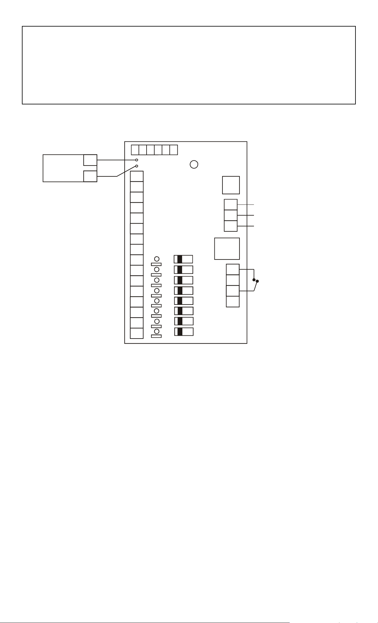
FIG. 1: POWER SUPPLY WIRING WITH CCS8M BOARD
BLACK
BATTERY
PACK
(OPTIONAL)
TERMINALS R1-R8
COMMON NEGATIVE
DC RETURN (0 VOLT)
CLASS 2 TERMINALS P1-P8
SUPPLY +V OUT.
EACH TERMINAL IS ON
A SEPARATE POLYSWITCH
WHICH IS APPROPRIATE
FOR INSTALLATIONS
WITH MULT IPLE LOADS
_
RED
+
NC
R1
R2
R3
R4
R5
R6
R7
R8
P1
P2
P3
P4
P5
P6
P7
P8
LOW
BATT
C
BB+
NCCNO
NO
AC
FAIL
ON
OFF
GREEN
LED
AC
FUSE
H
N
G
DC
FUSE
F1
FA
F2
H
OPERATION OF AC AND DC
FUSES IS DESCRIBED IN
SECTION 3.6
115 VAC INPUT
HOT
NEUT
G
R
N
D
FIRE ALARM
N.C. CONTACTS
OPEN WHEN
ALARM ACTIVE
H” TERMINAL IS SINGLE, HIGH
CURRENT OUTPUT (UPSTREAM
OF POLYSWITCHES)
SLIDE SWITCHES POWER AND DE-POWER EACH
P” OUTPUT. LED’S SHOW OUTPUT STATUS
3.7 BATTERY CHARGING CAPABILITY
A resistor and diode are present on the CCS8M board which, together with the power supply,
constitute a battery charging circuit appropriate for standby rated sealed lead acid or gel cell
batteries. Dry cell or NICAD batteries must not be used. Batteries are an option. The
power supply can be used with or without them. The battery pack of th e appropriate voltage is
connected to the red and black flying leads following correct polarity. In the event of a line
voltage power failure, the batteries will automatically drive the load at the same DC voltage. If
the emergency release terminals are opened, battery power will, however, be blocked just as
normal power from the power supply would be.
The components utilized on the CCS8M board for battery charging function for battery packs up
to 20 amp hours in capacity whether 12 or 24 volts. Larger batte ry packs can b e handled but
Securitron must be informed so that the board may be modified. Consult (Figure 2) to calculate
the correct battery pack based on desired backup time and the current drawn by the loa d. For
proper battery charging, the power supply must be set at 27 volts for a 24 volt system,
and 13.5 volts for a 12 volt system. Securitron power supplies are factory se t to this level
and if it is not maintained, the batteries will not hold their full capacity, and may even be
damaged.
PN# 500-19400
Page 4 Rev. E, 02/11
Page 5

FIG 2: CHART TO DETERMINE SIZE OF BATTERY PACK
BACKUP TIME DESIRED
MIN 1 HR 2 HR
4 HR
UL STD.
8 HR 16 HR 24 HR 48 HR 72 HR
150 MA
300 MA
500 MA
1 A
2 A
3 A
4 A
5 A
7.5 A
4 AH
4 AH
4 AH
4 AH
4 AH
4 AH
4 AH
4 AH
4 AH
4 AH
4 AH
4 AH
4 AH 4 AH
4 AH 4 AH
4 AH
4 AH 4 AH
4 AH
8 AH
8 AH
12 AH
16 AH
8 AH
12 AH
16 AH
16 AH
20 AH
4 AH
4 AH
4 AH 4 AH
8 AH
12 AH
16 AH
20 AH
24 AH
36 AH
12 AH
20 AH
24 AH
32 AH
40 AH
60 AH
4 AH
4 AH
8 AH
12 AH
20 AH
28 AH
36 AH
44 AH
72 AH
4 AH
8 AH
12 AH
20 AH
36 AH
52 AH
72 AH
84 AH
130AH
8 AH 8 AH 12 AH
12 AH 16 AH
16 AH
24 AH
48 AH
72 AH
100AH
120AH
180AH
24 AH
48 AH
100AH
150AH
200AH
240AH
360AH
24 AH
72 AH
150AH
240AH
300AH
360AH
480AH
TOTAL CURRENT DRA WN
10 A
4 AH
20 AH
28 AH
48 AH
"MIN" TIME REFERS TO FACIL IT Y USING A GENERATOR WHERE THE BATTERIES
ARE ONLY REQUIRED TO OPERATE THE SYSTEM FOR A FEW MINUTES
U.L. STANDARD REQUIRES 4 HOURS OF BATTERY OPERATION FOLLOWED BY
A 24 HOUR RECHARGE PERIOD AND THEN A SECOND 4 HOURS OF OPERATION
STANDARD SECURITRON POWER SUPPLIES CAN ONLY CHARGE UP TO A 20AH PACK.
IF A LARGER PACK IS CALLED FOR, THE FACTORY MUST BE ALLERTED TO SUPPLY
MODIFIED EQUIPMENT . LARGER PACKS ARE SHOWN IN ITALIC S IN THE CHART .
BATTERIES MUST BE SEALED LEAD ACID OR GEL CELL TYPES.
DRY CELLS WILL NOT RECHARGE AND WILL BE DAMAGED.
THIS CHART IS ONLY VALID IF BATTERIES ARE OPERATED
AT ROOM TEMPERATURE. IN A COLD ENVI RONMENT, CAPACITY IS REDUCED.
BATTERIES SHOULD BE REPLACED AFTER 5 YEARS OF USE.
72 AH
100AH
180AH
240AH
480AH
720AH
36 AH
3.8 CODE APPROVED WIRING METHODS
Note that these units are Class 2 rated. This means that the individual DC outputs of the
supplies (on “P” terminals) are current limited and can pose neither a high voltage nor high
energy hazard outside of the enclosure. Electrical building codes in most jurisdictions permit
Class 2 wiring to be done “in the open” rather than in conduit. To maintain the Class 2
ratings on the “P” terminal outputs, never connect them together to obtain higher capacity.
If you require higher capacity use the “H” terminal but the “H” terminal is high current (not Class
2) and must be in conduit. The line voltage wiring coming into the unit also must be in conduit
as it poses a high voltage hazard. Be sure to check with your local building department to
make sure you are complying with applicable wiring codes before installing these units.
4. SLAVE BOARD
Your power supply may include more than one control board. If so, the other board will be a
"slave" board (part # CCB-8) whose only purpose is to provide eight additional "P”, and "R"
terminals. The board will not be fully populated as the functio ns of AC input, battery charging,
emergency release, voltage supervision and DC and AC fusing are only needed on the CCS8M
board. The eight additional Class 2 “P” terminals naturally constitute individual outputs
protected by Polyswitches and including zone LED’s and slide switches.
5. APPROVALS
All Securitron power supplies are tested by various agencies. Consult the label inside the supply
to be advised of current approval status
PN# 500-19400
Page 5 Rev. E, 02/11
Page 6

6. MAGNACARE LIFETIME REPLACEMENT WARRANTY
For warranty information visit www.securitron.com/en/site/securitron/About/MagnaCare-Warranty/
PN# 500-19400
Page 6 Rev. E, 02/11
 Loading...