

Securitron FA-XDT-24, FA-XDT-12, EXD-1L, BA-XDT-12, BA-XDT-24 Installation Instructions
...Page 1

Securitron Magnalock Corp. www.securitron.com ASSA ABLOY, the global leader
Tel 800.624.5625 techsupport@securitron.com
in door opening solutions
SECURITRON MODEL XDT-12 AND XDT-24 EXIT DELAY TIMERS
INSTALLATION AND OPERATING INSTRUCTIONS
1. DESCRIPTION
The XDT-12 and XDT-24 are specialized exit delay timers designed to be integrated with fail safe
electric locks and switch equipped devices for delay initiation and reset. This creates a modular
door control package which fully meets American and Canadian building codes for delayed exit
(Special Locking Arrangements). See Section 3 for detailed information on these codes. As the
part numbers show, separate versions of the XDT exist for operation on 12 or 24 VDC.
The power of the XDT, however, goes considerably beyond meeting the code requirements.
Delayed exit is only one aspect of door control in sophisticated facilities. The XDT includes
optional functions that can be employed in entry control, do or/lock monitoring, and authorized
immediate exit. External switches such as time cl ocks can also put the XDT into dif ferent mode s
if delayed exit is not desired at all times.
To simplify the installer's task in understanding these instru ctions, we first describe delayed exi t
which is the primary function of the XDT. Later sections describe the timer's optional function s.
These sections can be quickly browsed to see if any of the functions will improve the installation.
2. DELAYED EXIT FUNCTIONS
Exact code requirements for delayed exit vary somewhat in different jurisdictions. These
detailed variations will be addressed in Section 3. In general, however, delayed exit includes the
following components and sequences of operation.
In the normal condition, the door is locked. The locking device must be a fail safe electric lock
(secure when powered). It is most commonly an electromagnetic lock such as Securitron's
Magnalock. An initiate device is used to start the exit sequence. The XDT timer requires that
the initiate device includes a normally closed dry switch which opens to start the sequence. The
safest type of initiate device is one that relies on no special knowledge for operation.
Securitron's Touch Sense Bar is an excellent choice for non fire rated doors. A sw itch equipped
fire rated panic bar is appropriate for fire rated doors. Push buttons a re also used but they may
not be acceptable to local building officials on the grounds of requiring special knowledge. O ther
initiate devices include mats, curtain detectors and monitoring strikes.
Once the initiate switch opens, a nuisance delay period begins. The nuisance delay p eriod may
be set for 1, 2 or 3 seconds. The duration of the nuisance delay period will depen d on the local
code and/or on the desires of the end user. The nuisance delay function can also be disa bled.
During the nuisance delay period, the XDT provides a pulsing relay output which is typically use d
to operate a local alarm horn or Sonalert. This notifies the person at the door that he has
activated the initiate device. If he intends to exit, he must maintain pressure on the device u ntil
the end of the nuisance delay period. If he releases the initiate device before the nuisance dela y
times out, the local alarm signal will stop and the doo r will revert to normal (lo cked) mode. The
sole purpose of the nuisance delay function is to deal with accidental triggering of the initiate
device. It makes particular sense to employ the nuisance delay in buildings occupied by a
changing population which will not be familiar with the exit control system. Retail stores or
museums are good examples of such buildings.
Once the nuisance delay times out (or immediately if no nuisance delay has been set) the
release delay period begins. The XDT's local alarm output will go from pulsing to stead y. This
will alert the person at the door that he need no longer maintain activation of the initiate device.
Once the release delay begins, it is irrevocable. The door will release at the end of the period.
Code mandated duration of the release delay period is 15 se conds although certain jurisdictions
allow extension to 30 seconds by local building or fire safety officials. The release delay period
on the XDT can therefore be set for 15 or 30 seconds and this total release delay time includes
the nuisance delay. For example, if a 2 second nuisance delay is set, the remaining release
delay will automatically be 13 or 28 seconds for a total of 15 or 30 seconds.
© Copyright, 2011, all rights reserved PN# 500-14900
Page 1 Rev. D, 06/11
Page 2
Once the door has released, it will remain released until manually relocked by a reset device.
This is a normally closed switch which is momentarily activated. Relocking actually occurs on
reclosure of the switch. Most commonly the reset device is a momentary spring loaded
keyswitch such as Securitron's model MK. We recommend that the keyswitch be mounted at the
door as this insures that security staff will actually i nspect the door. In some jurisdictions the
reset device may be a doorswitch. With a doorswitch, relocking occurs from the act of exiting
the door. Certain codes require the use of a doorswitch as will be discussed in Section 3. The
American BOCA code does require use of a doorswitch and also has a special and unique timed
relocking sequence which is explained in section 3.4.
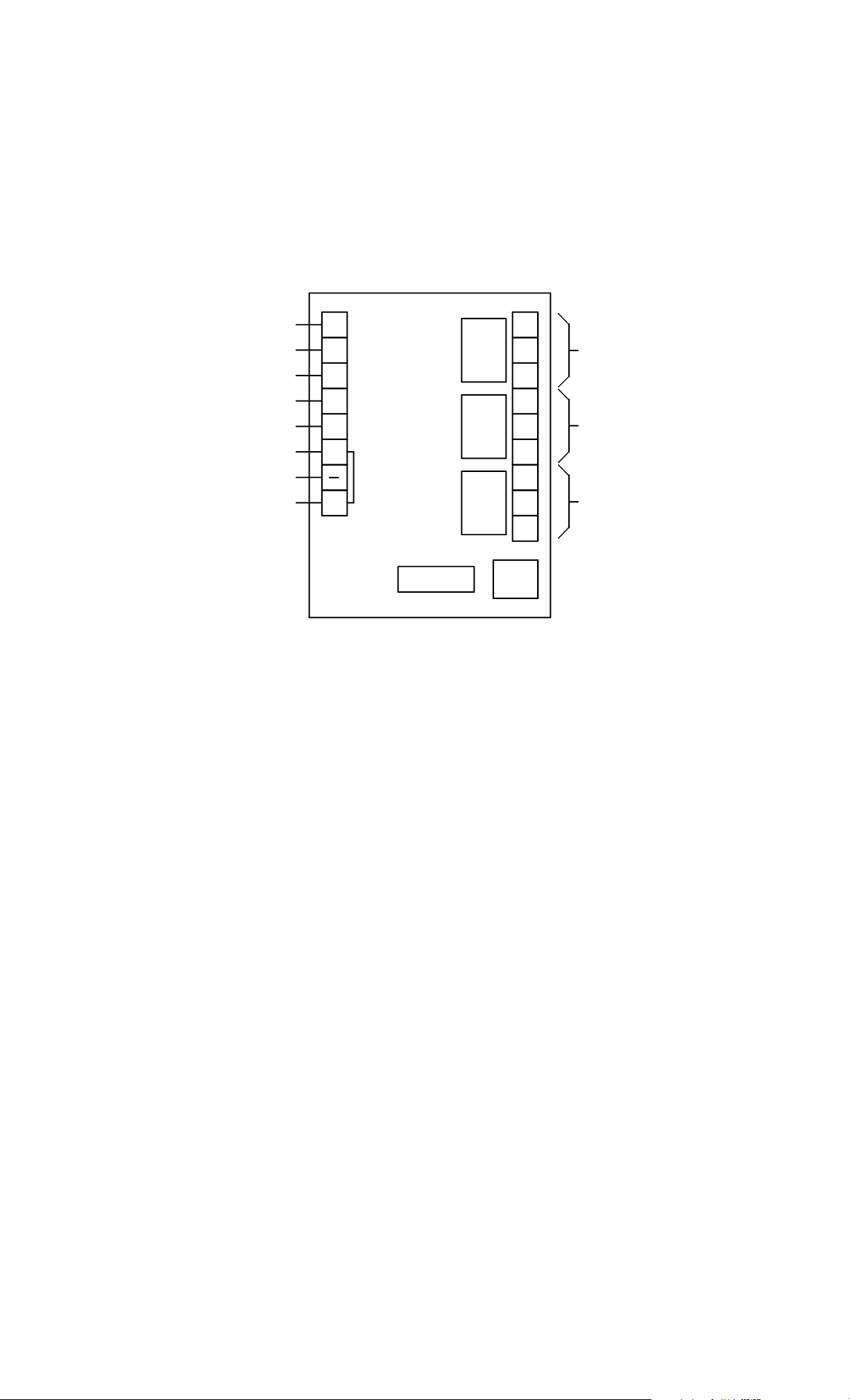
FIG. 1: OVERVIEW OF XDT BOARD
DELAY CONTROL TERMINAL
RESET INPUT
INITIATE INPUT
FREE EGRESS INPUT
BYPASS INPUT
LOCK STATUS INPUT
0V (NEG) POWER
+V POWER
NOTE: INPUTS OPERATE
BY BEING CONNECT E D TO +V
DC
RS
IN
FE
BP
LS
+
NC
C3
NO
NC
C2
NO
NC
C1
NO
DIPS
LOCK CONTROL
RELAY
NORMALLY ENERG IZ E D
REMOTE ALARM
RELAY
NORMALLY ENERGIZED
LOCAL ALARM
RELAY
NORMALLY DEENE RG IZED
Use of the "local alarm relay" as shown in Figure 1 is required by code to signal at the door that
the system is working. The local alarm relay pulses during the nuisance delay period and
steadily energizes during the release delay period. At the end of this period, when the lock
releases, the local alarm relay deenergizes. This informs the person exiting that the door may
be used. A second relay (shown above) is called the remote alarm relay. This relay is
normally energized; it deenergizes to show an alarm condition. It signals alarm from the
beginning of the release delay period until the door is relocked. The remote alarm relay is
intended to signal to a security office that a se curity violation i s occurr ing at the d oor. It ign or es
the nuisance delay period as this should be seen as a "false alarm" unless the delay becomes
irrevocable. It also continues to signal until the door is relocked, correcting the security
violation. The remote alarm relay should also be considered a general "trouble" signal. If the
board loses power, this relay will deenergize signaling trouble. It is also used to signal other
optional alarm conditions described in Section 7.
3. SPECIFIC CODE REQUIREMENTS
We must strongly emphasize that the following sections on code requirements should not be
considered definitive. They represent Securitron's best understanding of the individual code s at
the time of this manual's most recent revision. Codes, however, can change suddenly an d are
also subject to local interpretations that may diff er from the descripti ons that follow. You shou ld
consider these descriptions as a starting point which should be confirmed or altered by the local
authority having jurisdiction.
In the following 5 sections, we describe individual code requirements in 4 functional areas:
Nuisance delay, Release delay, Relocking and Power. The main issue in the Power function is
whether or not battery backup can be applied to the locking system to keep the d oor functional
in a local power failure.
All of the codes call for immediate release of all locks in the event of activation of the fire
detection system. The proper way to accomplish this is by employing an auxiliary latching relay
with contacts of appropriate size to handle the total lock load. The relay should be a listed part
of the fire detection system and all lock system DC power should flow through its NC contacts.
The individual codes also typically specify the type of fire detection system that must be in place
PN# 500-14900
Page 2 Rev. D, 06/11
Page 3

and limit use to certain occupancy types. These details do not affect how the XDT board is
configured so they are beyond the scope of this manual. We recommend strongly, however,
that the end user assure himself that his occupancy and fire detection system qualify
to support delayed exit in his local area.
These exit delay timers have only been evaluated by UL for use in the EXD-1 and EXD-1F FWAX
systems.
3.1 NFPA 101 (SPECIAL LOCKING ARRANGEMENTS)
This code by the National Fire Protective Association was the first implementation of delayed
exit. It formed the basis for the different model code versions which follow and is still used in
many specifications.
NUISANCE DELAY: Permitted up to 3 seconds.
RELEASE DELAY: 15 seconds or extension to 30 seconds with local approval.
RELOCKING: Must be "manual". This is generally interpreted to mean that a doorswitch ca n not
be used for relocking. A keyswitch is the typical technique used.
POWER: The door must release when DC power to it is cut off. This m eans that battery backup
of the system power supply can be considered acceptable, but this is a point to confirm with the
local authority.
3.2 STANDARD BUILDING CODE
NUISANCE DELAY: Not allowed.
RELEASE DELAY: 15 seconds or extension to 30 seconds with local approval.
RELOCKING: Must occur only when the door opens. A do orswitch rather than a keys witch must
be used.
POWER: The door must release when DC power to it is cut off. This m eans that battery backup
of the system power supply can be considered acceptable, but this is a point to confirm with the
local authority.
3.3. UNIFORM BUILDING CODE
NUISANCE DELAY: Required and must be set at 2 seconds.
RELEASE DELAY: 15 seconds only.
RELOCKING: Must be "manual" and must be located at the door. This is generally interpreted to
mean that a doorswitch can’t be used for relocking. A keyswitch is typical.
POWER: The door must release when power to it is cut off. The door must also release if power
to the smoke detection system or exit illumination system is lost . This is g enerally a ccomp lish ed
by using the same line voltage source to operate the lock power supply as o perates the smoke
detection and exit illumination systems. Battery backup for the locks is normally excluded.
3.4 BOCA
NUISANCE DELAY: Required and must be set at 1 second.
RELEASE DELAY: 15 seconds or extension to 30 seconds with local approval.
RELOCKING: A doorswitch must be used and a special type of timed relocking is required. After
the release delay expires, the lock releases. When the door is opened, the doorswitch chan ges
state but nothing happens immediately (the lock remains released). When the door re closes, a
"relock delay" of 30 seconds begins. If the door is not opened again during this 30 second
period, it will relock. If it is opened again, the 30 second relock delay will begin again on door
closure. The door will only relock when it has been left undisturbed for 30 seconds after
reclosure. The local authority may extend the relock delay to 45 seconds f or sensitive facilities.
The standard XDT board supports the BOCA 30 second relock sequence. If the 45 second relock
sequence is required, contact the factory to receive a modified board.
POWER: The door must release when power to it or to the building is cut off. Battery backup of
the lock power supply is therefore specifically excluded.
PN# 500-14900
Page 3 Rev. D, 06/11
Page 4

3.5 NATIONAL BUILDING CODE OF CANADA
NUISANCE DELAY: Not allowed.
RELEASE DELAY: 15 seconds only
RELOCKING: Must be "manual". This is generally interpreted to mean that a doorswitch ca n not
be used for relocking. A keyswitch is the typical technique used.
POWER: The door must release when power to it or to the building is cut off. Battery backup of
the lock power supply is therefore specifically excluded.
4. DIP SWITCH SETTING
Once you have determined the values to be set for nuisance delay, release delay and whether
you want BOCA relocking used, dip switches on the board may be set to select these
parameters. The factory set condition of the board is nuisance delay disabled, 15 second release
delay and standard (non BOCA) relocking. If you require a variation from this configuration,
some Dip Switch settings will have to be altered. When cha nging Dip Switch settings, note that
the board must be repowered as the switch settings are read on power up.
Switch 1: This sets the amount of
time for release delay. In the factory
set (Off) position, release delay is set
for 15 seconds. Turning the switch On
sets a 30 second release delay.
Switch 2 and 3: The combined position
of the 2 switches selects 4 different
values for nuisance delay.
15 SEC. RELEASE DELAY 30 SEC. RELEASE DELAY
MATRIX (SEE TEXT)
MATRIX (SEE TEXT)
STANDARD RELOCK ING
FACTORY SETTINGS SHOWN IN BLACK
DIP
SWITCHES
1
2
3
4
0N
OFF
MATRIX (SEE TEXT)
MATRIX (SEE TEXT)
BOCA RELOCKING
MATRIX #1: Switch 2 Off; Switch 3 Off (factory set): nuisance delay disabled
MATRIX #2: Switch 2 On; Switch 3 Off: 1 second nuisance delay
MATRIX #3: Switch 2 Off; Switch 3 On: 2 second nuisance delay
MATRIX #4: Switch 2 On; Switch 3 On: 3 second nuisance delay
Switch 4: This implements BOCA timed relocking. In the factory set (Off) position, standard
relocking from a momentary reset switch is implemented.
When the switch is turned On, 30 second delayed BOCA relocking is set. Under some conditions,
local authorities may require a 45 second delayed BOCA relocking. The standard XDT board
does not support this. Contact the factory to order a modified board with the 45 second feature.
See section 3.4 for a description of BOCA relocking.
5. POWER
Two versions of the XDT exist which operate respectively on 12 or 24 VDC. Volt age can vary
from -10% to +20% and must be filtered or regulated. Pulsating DC (transformer +
bridge rectifier) is not acceptable. If you are forced to use pulsating DC, install a 1000
Microfarad capacitor across the board's "+" and "-" terminals to create a filter. The reason why
the XDT is not a dual voltage board is that it includes 3 relays and therefore draws a relatively
large amount of current. Supplying separate versions for the 2 voltages minimizes the current
draw but the board will still draw a maximum of 100 mA at 12 VDC or 50 mA at 24 VDC.
As this is high for a timer, be sure that your power supply is of adequate capacity to support the
load of the board with that of the electric lock.
A related power issue is a description of how the board behaves upon loss of pow er or reduction
of the input voltage. It is always intended that the XDT is permanently powered except
in the event that the fire alarm system removes all power from the delayed exit
locking system.
In the "normal" condition, the lock control relay (C3) and the remote alarm relay (C2) are
energized. The local alarm relay (C1) is deenergized. In this condition, the lock is powered
(secure) and no alarms are being signaled. If the board loses power from a broken wire for
instance, the lock control relay will deenergize releasing the electric lock. This is a safety
feature. The remote alarm relay will also deenergize which will sign al trouble at the door. This
PN# 500-14900
Page 4 Rev. D, 06/11
Page 5

is a security feature. The local alarm relay will remain deenergized and there fore not signal at
the door as the local alarm relay is intended to signal a delayed exit event and without p ower,
the board is not capable of producing such an event; the lock is immediately releas ed upon loss
of board power.
If the system has been approved for the use of battery backup, loss of building power will no t
immediately alter anything at the door as the batteries will take over. If power is out for an
extended period of time, however, the batteries will begin to drain and lose voltage. As an
additional safety feature, the XDT includes a low voltage sensing circuit. The board will
keep working normally as the voltage declines until it reaches roughly 70% of nominal. At that
point, the XDT will automatically act as if all power was removed. The lock releases and the
remote alarm relay deenergizes, signaling trouble at the door.
6. WIRING
Six additional components are needed to create a delayed exit installation built around the XDT:
Power supply, fail safe lock, initiate switch, reset switch, local alarm sounder and MOV.
Interconnection of these components is shown in the drawing below. The MOV is a "button" like,
2 wire component packed with the XDT board. It is instal led in parallel with the fail safe lock
and its function is to absorb the inductive kickback which is generated when the lock is sw itched
off. If the MOV is omitted, electronic noise from the lock may interfere with proper operation of
the board and relay life will be shortened. If you are used Securitron's Magnalock in the
installation, the MOV may be omitted because the Magnalock has internal inductive kickback
protection.
FIG. 2: TYPICAL XDT WIRING
RESET (NC)
INITIATE (NC)
0V (NEG)
+V
DC
RS
IN
FE
BP
LS
+
NC
C3
NO
NC
C2
NO
NC
MOV
FAIL SAFE
LOCK
C1
FROM POWER SUPPLY
NO
LOCAL
ALARM
NOTE: MOV NOT NEEDED IF SECURITRON MAGNALOCK IS USED
Note the following points refer to the drawing on this page.
The board receives 12 or 24 VDC according to the version selected.
Power must be supplied at all times except in the event that the fire alarm system activates.
The switches used for delay initiation and reset (relocking) must be normally closed.
The fail safe lock operates on the same power that operates the board so that it will be safely
released in the event of a fire.
The local alarm is typically a Sonalert or other DC horn.
As factory delivered, terminal "+" is jumpered to "LS" to disable lock status sensing. This
optional monitoring feature is described in section 7.1.
The MOV supplied with the XDT must be wired as shown, unless Securitron's Magnalock is
used as the locking device.
PN# 500-14900
Page 5 Rev. D, 06/11
Page 6

7. OPTIONAL FUNCTIONS
The following optional functions are not necessary to meet delayed exit safety codes but may be
implemented as desired to increase the utility of the application.
7.1 LOCK STATUS REPORTING
The LS input is for optional lock (or door) status reporting. Note that when the XDT is d elivered,
the LS terminal is jumpered to the "+" terminal. In this mode, the board interprets the lock as
being secure so no reporting occurs, and the board can be used for normal delayed exit.
To implement lock status reporting, a lock status switch, door switch or positive voltage signal
should be connected to LS so that +V is present on LS when the lock o r door is secure. If the
lock or door stops reporting secure when the door has not been released by the board, the
remote alarm relay will switch 5 seconds later and remain switched unt il LS again receives +V.
The purpose for the 5 second delay is to allow a door to reclose an d again report secure after
legitimate use. If any function of the XDT board has released the door, the LS input will be
ignored until the board has relocked the door. This feature allows use of the XDT board to
perform exit delay and yet also report on propped doors or forced doors.
FIG. 3: OPTIONAL LOCK STATUS AND BYPASS FUNCTIONS
WHEN +V IS CLOSED TO "BP", THE LOCK WILL RELEASE
AND ALL ALARMS WILL BE SUPPRESSED. USE WITH AN
ALTERNATE SWITCH ALLOWS RELEASE OF THE LOCK
FOR A PERIOD OF TIME. USE OF A
MOMENTARY SWITCH RELEASES THE LOCK
FOR 5 SECONDS TO
PERMIT AUTHORIZED
USE OF THE DOOR.
DC
RS
IN
FE
BP
LS
NC
C3
NO
NC
C2
NO
NC
+
WHEN DOOR OR LOCK STATUS SWITCH
CONNECTS +V TO "LS" , THE DOOR IS
CONSIDERED SE CURE . IF THE SWITCH
OPENS WHEN THE DOOR SHOULD BE
SECURE, THE REMOTE ALARM RELAY
WILL SIGNAL AFTER A 5 SECOND DELAY AND REMAIN IN THIS
STATE UNTIL THE SWITCH CLOSES AGAIN. THE WHITE WIRE OF
A SECURITRON "S" MAGNALOCK CAN CONN E CT DI RE CTLY TO
"LS".
C1
NO
7.2 BYPASS FUNCTION
The optional bypass function has two purposes: door release for extended periods and
authorized entry or exit through the door. Release for extended periods is usually implemented
on a time schedule. A door may be released all day and put into delayed exit mode at night for
security. To accomplish this, +V is simply switched into the BP terminal by a time clock or other
alternate action switch. When the BP input is receiving +V, the lock is released and all other
functions of the board are suppressed. The initiate switch will not start nuisance or release
delay and lock status monitoring is suppressed since, during bypass, the lock is n ot supposed to
be secure. The two alarm relays will remain in their normal states.
For authorized door use, a momentary switch connects between BP and +V. When the switch
closes, the door releases. When the switch reopens, the door remains released for 5 seconds.
This is called an "off delay" function. When the BP terminal is used in this manner with a
momentary switch, timed authorized entry or exit can be performed.
A typical application for the bypass function is the use of a double momentary keyswitch such as
Securitron's model MK with MKS second switch. When turned in one direction, the MK will
perform relocking after a delayed exit event. When turned in the other direction, the MK will
perform bypass so that an authorized person will be able to release the door for 5 seconds for
immediate egress without creating any alarm. In similar fashion, a momentary keyswitch can
operate the bypass function from the exterior of the door for authorized timed entry.
PN# 500-14900
Page 6 Rev. D, 06/11
Page 7

A special situation arises if a momentary bypass switch is u sed during the release delay period.
The lock releases immediately for as long as the bypass switch is closed. The 15 or 30 second
release delay countdown continues "in the background" as by code, this process is irrevocable.
If the bypass switch reopens before the release delay expires, the lock will resecure and
correctly release again when the underlying release delay times out. The bypass switch,
therefore can be used for momentary immediate exit or entry during the release delay period
without affecting code legal operation of the board.
7.3 FREE EGRESS FUNCTION
The free egress function puts the board in a different operating mode. When +V is switched to
terminal FE by an alternate action switch, the board goes into free egress mode. I n this mode,
use of the initiate device, immediately releases the door for egress. When the initiate device is
released, the door immediately relocks. Often, a time clock such as S ecuritron's model DT-7 is
used to put the door into free egress mode during the day and exit delay mode at night.
FIG. 4: OPTIONAL FREE EGRESS AND LOCKDOWN MODES
AN EXTERNAL ALTERNATE SWITCH IN PARALLEL WITH
INITIATE (NC)
WHEN +V IS SWITCHED TO "FE",
THE BOARD IS IN FREE EGRESS
MODE. TH E INITIATE S WITCH
IMMEDIATELY RELEASES THE LOCK
WITH NO ALARM, EXCEPT
OPTIONALLY FROM THE LOCK STATUS MONITORING FUNCTION.
INITIATE WILL PUT THE BOARD INTO LOCKDOWN.
INITIATE CAN NO T BE READ
DC
RS
IN
FE
BP
LS
+
NC
C3
NO
NC
C2
NO
NC
C1
NO
The free egress mode differs from the bypass mode as follows: When the door is bypassed, the
fail safe lock is released so that both entry and exit is freely possible. Also, during bypass mode,
the board performs no monitoring functions. In the free egress mode, the lock remains secure
so that entry is blocked, but egress without alarm signaling occurs immediately wh en the initiate
device is pressed. If lock status monitoring is in use, the remote alarm relay will still report a
door that doesn't resecure within 5 seconds after a free egress event.
The free egress function is most successfully used with a switched exit device such as
Securitron's Touch Sense Bar. Free egress occurs with a single motion. If a push button is
being employed, the button will have to be held and the door pushed open with the other hand.
7.4 LOCKDOWN MODE
It may be desired that exit delay be employed during the day but at night and weekends, when
the building is empty, the door should be locked with no unauthorized egress or entry possible.
This is most easily accomplished by the use of a time clock s witch, such as Securitron's model
DT-7, which will close across terminals "+" and IN to put the board into lockdown. This simply
shunts out the initiate device so that the board cannot respond to its use. If authorized entry or
exit is desired, the bypass function will still release the door for 5 seconds. If lock status
monitoring has been implemented, an alarm signal will still be created in the event of a forced
door or a bypassed door that doesn't relock. We recommend that use of lockdown mode be
checked with the local approving authority in advance.
7.5 LOCK POWERED AFTER RELEASE DELAY MODE (DELAY CONTROL)
PN# 500-14900
Page 7 Rev. D, 06/11
Page 8

In ordinary delayed exit, the fail safe lock releases after the de lay an d remains rele ased un til the
reset switch performs relocking. In facilities where a threat exists from the outside, the questi on
arises as to security against unauthorized entry after the release delay has expired. It may be
that the delayed exit cycle was initiated by mistake or as an act of vandalism. It may take som e
time for a guard to arrive at the door to effect relocking and there is always some risk that
security procedures will fail, despite the alarm si gnals, and the door will be left in this released
state for an extended period of time.
If a latch equipped panic bar is present on the door, some security will still exist against
unauthorized entry. However, many doors will employ a non latch equipped initiate device such
as Securitron's Touch Sense Bar. Also, any door which combines delayed exit with controlled
entry (such as from a card reader) must depend only on the fail safe lock for entry security.
The XDT can be set so that after the release delay expires, the fail safe lock remains
engaged so long as the initiate device is not being pressed. When the initiate device is
pressed, the lock immediately releases but resecures after the initiate device is no
longer being pressed. This preserves security from the outside. To implement this,
DC
RS
IN
simply run a wire from terminal DC to terminal IN. This is the only use for terminal DC.
We believe that this method of operation meets the intent of all exit delay codes but it is
certainly possible that conservative safety officials might reject it, so we advise that specific
approval be sought for this variation.
8. MAGNACARE LIFETIME REPLACEMENT WARRANTY
For warranty information visit: www.securitron.com/en/site/securitron/About/MagnaCare-Warranty/
PN# 500-14900
Page 8 Rev. D, 06/11
 Loading...