

Securitron BA-DPA-12, BA-DPA-24 Installation Instructions
Securitron Magnalock Corp. www.securitron.com ASSA ABLOY, the global leader
L
E
Tel 800.624.5625 techsupport@securitron.com
in door opening solutions
SECURITRON MODEL DPA-12 AND DPA-24 DOOR PROP ALARM TIMERS
INSTALLATION AND OPERATING INSTRUCTIONS
1. DESCRIPTION
The DPA series consists of a multifunction micropro cessor controlled timer. Its primary function
is a sophisticated door prop alarm with numerous functions and options that permit tailoring its
alarm functions to the specific requirements of the end user. It is available as a circuit board
mounted on snap track via the part numbers: DPA-12 and DPA-24. It is also available in a
lockable steel enclosure with Sonalert and LED mounted, via the part numbers: BA-DPA-12 and
BA-DPA-24. Applications for the DPA series include doors with or without electric locks installed.
2. CIRCUIT BOARD OVERVIEW
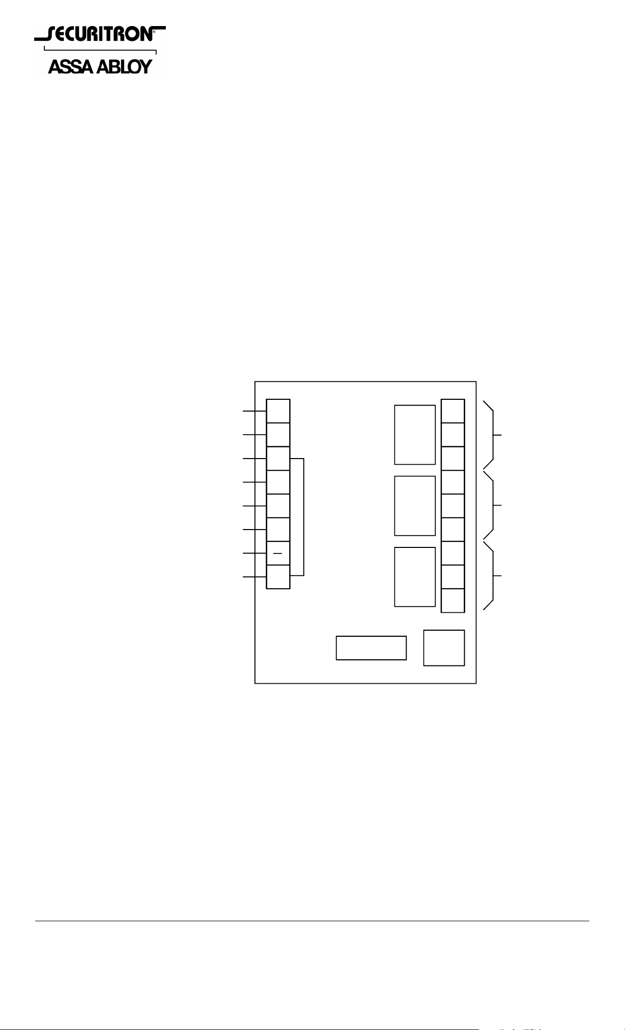
Refer to Figure 1. The DPA board consists of five logic inputs, three SPD T relay ou tputs and four
Dip Switches. Two terminals for polarized power input are also provided. The DPA series is
available in separate units for either 12 VDC or 24 VDC oper ation. Note that DC power must be
regulated or filtered. The unit will not operate on pulsating DC (transformer + bridge
rectifier). The 12 volt version draws a maximum of 100 mA and the 24 volt version draws a
maximum of 50 mA. These maximums are present when all three output relays are energized.
FIG. 1: CIRCUIT BOARD OVERVIEW
NOT USED
RESET INPUT
DOOR STATUS INPUT
DURESS INPUT
BYPASS INPUT
LOCK STATUS INPUT
0V (NEG) POWER
+V POWER
DC
RS
IN
FE
BP
LS
+
NC
C3
NO
NC
C2
NO
NC
C1
RELAY #3
RELAY# 3
NORMAL
NORMALLY
ENERGIZ
ENERGIZED
RELAY #2
RELAY #2
RELAY #1
NO
NOTE: INPUTS OPERATE
BY BEING CONNECTED TO +V
DIPS
3. BASIC OPERATION
The operation of the DPA occurs in four different stages. The first stage is the normal
condition. In this stage the door is closed/secure and inputs IN and LS are receiving +V. The
output relays are in their normal conditions: relays #1 and #2, deenergized and relay #3,
energized.
The next stage is the authorized condition. The door opens and time range one begins.
This range can be digitally set for 30, 60, 120 or 240 seconds. During the authorized conditio n,
the output relays remain in their normal states. The time period selected is the amount of time
that the user feels is acceptable for normal door use . N ote that it doesn't really matter if the
door is electrically locked and employs an access control device or if the door is sim ply equipped
with a panic bar. The central function of the DPA is to prevent doors being propped open too
long.
© Copyright, 2011, all rights reserved PN# 500-15700
Page 1 Rev. C, 04/11
The next stage is pre-alarm. If the door has not been reclosed/resecured before the end of the
authorized condition (time range one), relays #1 and #2 energize and time range two
begins. Relay #1 is connected to the Sonalert on the BA-D PA enclosure and the Sonalert will
sound at the door. Relay #2 is connected to the LED. Naturally, if you have purchased on ly the
board, it will be up to you how to connect these relays. Time range two can be digitally set for
0, 15, 30 or 60 seconds.
Note that when time range two is set to zero, the pre-alarm condition is eliminated and the
board goes directly into the alarm condition at the end of time range one.
The Sonalert sounding at the door during time range two should alert someone in the area to
resecure the door before the end of time range two. If this is done, the DPA returns to the
normal condition. If time range two expires with the door still not closed/secure, the DPA goes
into its final, alarm stage.
In the alarm stage, relay #1 follows the door/lock status. If the door is resecured, it will
deenergize. Otherwise, it will stay energized. Relay #2 remains energized. In the BA-DPA
version, relay #2 operates the LED. This provides a "memory" indication that this particular
door is the one which went into the alarm stage. Remember that the Sonalert will stop if the
door is reclosed/resecured. In the alarm stage, relay #3 deenergizes which is its alarm
condition (relay #3 is normally energized). Relay #3 is normally used to summon building
security personnel as in the alarm stage, the door is considered to have been propped open too
long. The reason that relay #3 is normally energized is to provide an alarm signal if
power to the DPA is interrupted. This calls for an alarm signal as the door is no longer being
monitored. Note that when you wire relay #3 while referring to Figure 1, the contacts are
labeled in their deenergized condition. This is the alarm condition as relay #3 is normally
energized.
The alarm stage is not limited by time. Recovery consists of resecuring/reclosing the door and
then executing a reset. If the door remains propped, reset is n ot possible. The reset signal ca n
be from a separate switch, such as a keyswitch at the door. This requires security personnel to
physically check the door. Alternately, reset can be taken from a door swit ch so that it will be
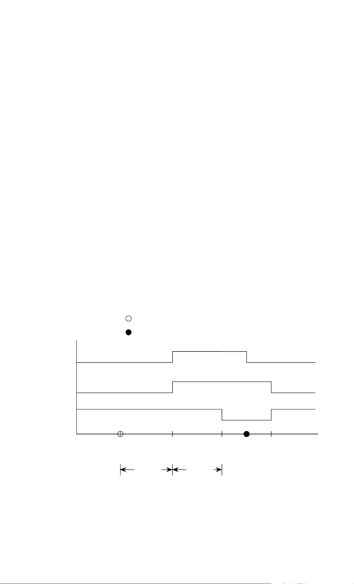
automatic when the door recloses. Figure 2 shows a graphic representation of basic operation of
the DPA, which makes the sequence of operation easier to understand.
FIG. 2: BASIC OPERATION OF THE DPA
E = ENERGIZED
D = DEENERGIZED
= DOOR OPENS
= DOOR RESECURES
E
RELAY #1
D
E
RELAY #2
D
E
RELAY #3
D
NORMAL
CONDITION
AUTHORIZED
CONDITION
TIME
RANGE
#1
PRE-ALARM
CONDTION
TIME
RANGE
#2
ALARM
CONDITION
RESET
(NORMAL)
A single graph cannot show all the operating features of the DPA, but Figure 2 does display the
basics of the product. Note the events that distinguish between the conditions. The authorized
condition begins when the door opens or becomes insecure. Time range one defines the length
of the authorized condition unless the door recloses before the end of time range one, in which
PN# 500-15700
Page 2 Rev. C, 04/11

case the DPA returns to normal condition. In the pre-alarm condition, relays #1 and #2 begin to
signal. The length of this condition is defined by time range two, unless the door recloses before
the end of time range two. In that case, again, the DPA automatically returns to the normal
condition. The alarm condition during which relay #1 follows door/lock status but relays #2 and
#3 are signaling will continue indefinitely until two things happen. First, the door must be
resecured and then, the DPA must receive a reset signal.
4. SETTING TIME RANGES 1 AND 2
Note that there are four Dip Switches on the board. They are labeled 1 through 4 and you can
also see that they can be set to labeled positions “on” or “off”. Dip Switches 1 and 2 allow you
to set time range 1 (authorized condition). Dip Switches 3 and 4 set time range 2 (pre-alarm).
The following settings allow four choices of time for each range.
TIME RANGE 1 TIME RANGE 2
DIP #1-OFF; DIP #2-OFF---30 Seconds DIP #3-OFF; DIP #4-OFF---0 Seconds
DIP #1-ON; DIP #2-OFF---1 Minute DIP #3-ON; DIP #4-OFF---15 Seconds
DIP #1-OFF; DIP #2-ON---2 Minutes DIP #3-OFF; DIP #4-ON---30 Seconds
DIP #1-ON; DIP #2-ON---4 Minutes DIP #3-ON; DIP #4-ON---1 Minute
5. WIRING FOR DOOR STATUS AND LOCK STATUS
Earlier in this manual, we have talked about the door being open or in secure interchangeably.
In fact these are two separate conditions and the DPA handles them in a sophisticated way
which includes a unique type of tampering detection.
There are various means of detecting the status of a door. The most common is a magnetic
door switch. This activates when the door opens an inch or so. It say s nothing about whether
the door is secure or not. In that sense, it is the poorest type of door status detection. If the
door is an unlatched swing through type, however, a magnetic door switch is the only device
that can be used.
When the door includes a latch, it is possible to detect the pres ence of the latch in the strike by
use of a "monitoring strike". This component includes a microswitch which is activated b y the
presence of the latch. Latch detection is superior to door position detection because it confirms
that the latch is engaged. Many doors that employ DPA's include a panic ba r or exterior locked
knob set which permits free egress but not entry. Latch detection in this instance qualifies as
lock status detection as it shows that the door is secure against entry.
Electrically locked doors often allow lock status detection. If an electric strike is mounted, some
models include a signal to show that the latch is engaged. Electromagnetic locks generally offer
lock status detection as an option. Securitron's Senstat Magnalocks are an example.
The issue for use of the DPA is whether you wish to use one signal for initiating the
functions or two. The advantages of using one are lower costs and simplicity. The advantages
of using two are higher security against tampering as will be explained shortly.
When you are using a single door status signal to activate the DPA, select the
highest security signal that you have available. Lock status is better than
door status. Regardless of the signal selected, however, it must be
input to terminal LS and the factory installed jumper between
terminal "+" and terminal IN must be left in place. Terminal IN can
never be used as the only input to activate the unit. It can only be used in
concert with terminal LS.
ACTIVATE
SWITCH IS
CLOSED
WHEN
DOOR IS
SECURE
DC
RS
IN
FE
BP
LS
Note the drawing on the right. The jumper is correctly installed between IN
and "+". The door status or lock status switch is installed between "+" and
LS so that it is closed when the door is secure. The DPA w ill start its timing
+
functions when this switch opens so that +V is no longer being fed to terminal LS. Note that if
you are using Securitron's "S" Senstat Magnalock at the door, it provides a direct +V status
signal on its white wire. You need only connect the Magnalock's white wire to terminal LS.
PN# 500-15700
Page 3 Rev. C, 04/11
 Loading...