

Securitron AQU244-16C, AQU244-16C16R, AQU244-16F16R, AQU244-8C, AQU244-8C1R Installation Instructions
...Page 1
AQU244 & AQU128 Series Installation Instructions
Securitron Magnalock Corporation
10027 S. 51st St., Ste.102
Phoenix, AZ 85044
Doc.#500-33020: Rev. A: Installation specifications subject to change without notice
Phone: (800) MAGLOCK
customercare@securitron.com
www.Securitron.com
AQU244
24vdc 5A Supervised Power Supply/Charger module
mounted in a Large Enclosure with Smart Fan 14” x
14” x 4.75”
AQU128
12vdc 10A Supervised Power Supply/Charger module
mounted in a Large Enclosure with Smart Fan 14” x 14”
x 4.75”
-8C1R
-8F8R
-8C8R
-16F16R
-16C16R
AQU244 with one PDB-8C1R
AQU244 with one
PDB-8F8R (Fuses)
AQU244 with one PDB-8C8R Module(Circuit Breakers)
AQU244 with two
PDB-8F8R (Fuses)
AQU244 with two PDB-8C8R Modules(Circuit Breaker)
-8C1R
-8F8R
-8C8R
-16F16R
-16C16R
AQU128 with one PDB-8C1R
AQU128 with one
PDB-8F8R (Fuses)
AQU128 with one PDB-8C8R Module(Circuit Breakers)
AQU128 with two
PDB-8F8R (Fuses)
AQU128 with two PDB-8C8R Modules(Circuit Breaker)
Installation Instructions
Features:
Universal Input 90-240 vac
Certified Compliance with EN 55022 & FCC
Thermal Protection
Short Circuit Protection
Precision Battery Charging and
Output Regulation.
Smart Fan runs as Needed
for Cool Operation and Long Life
Output ON/OFF Service Switch
(no service switch on CE marked units)
Outputs are Power Limited
for Class II Using PTC Circuit Breakers
Indicating LED’s for:
AC Input, Power Normal, DC On,
Main Power at Each PDB-8C, and Every
Output
Power Trouble Alarm (form C Contact)
Indicates AC Power Fail, Low Battery or Output
Voltage too High.
Battery Cut-off Relay Prevents Deep Discharge
Battery is Float Charged for Faster Charging
with No Switch Over when AC fails.
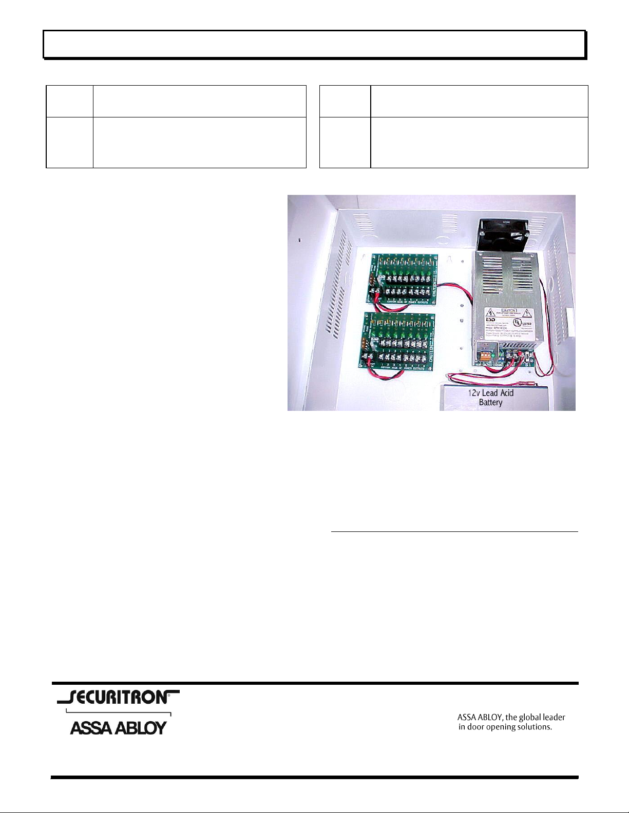
Shows AQU128
with Smart Fan and Enclosure
12” Plug-in Battery cable assembly is provided
with series cable for the AQU244 models.
36” Plug-in Battery cable assembly is available
(WA-36IBAT) for remote battery mounting.
Quality Manufactured in the USA
AQU244 & AQU128 Description
The AQU244 and AQU128 are clean, efficient, heavy duty, low frequency off line switching power supplies with
battery charger and power supervision. Even though the wattage is the same for the AQU244 and the AQU128, we
sell them separately for optimum performance. The AQU244 and AQU128 use a very low switching frequency of
23KHz, just above our hearing range. This, coupled with extensive filtering, provides a balance of super clean
power and efficiency. This low frequency also eliminates interference problems with card readers. The AQU244
and AQU128 are self-contained with a universal line input of 90 to 264vac. The AQU244 and AQU128 each weigh
less than 1.5 lbs and occupy less than ½ of a cubic foot of cabinet space.
The AQU244 and AQU128 become an uninterruptible power supply when a stand by battery(s) is connected with
the supplied cable. These supplies have a special power limiting circuit that allows the batteries to be float charged
Page 1 of 5
Page 2

AQU244 & AQU128 Series Installation Instructions
across the output without lock up or chirping on and off. The battery(s) is protected with an automatic resetting
circuit breaker and diode for over current and accidental reversed battery hookup. Float charging means faster
recovery time for the battery(s). There is no switch over or voltage drop when power fails. Standby battery(s) can
be any capacity between 4 and 40 Amp hours. The precise output voltage provides longer battery life. The
AQU244 24vdc is rated for 4 Amps continuous current with 1 Amp reserved for battery charging. The
AQU12812vdc is rated for 8 Amps continuous current with 2 Amps reserved for battery charging.
Power Supervision includes a battery cut off relay and a separate power trouble alarm relay. The battery cut off
relay removes the battery from the load when the battery reaches its service limit. This prevents damage to the
battery from going into deep discharge. The power trouble alarm relay output, form C contacts, can be used to
signal a buzzer and/or other signaling device. The relay is normally energized for fail-safe operation. The relay has
a green LED that is on when power is good. The relay will drop off of normal when the standby battery(s) reaches
about 70% of capacity after a power a power failure. This low voltage indication represents power trouble. High
voltage failure will also indicate power trouble.
A Service Switch is provided to disable the power output. When the switch is turned off, the power supply is
electronically disabled and the battery cut off relay is de-energized to remove battery from the output terminal. The
switch is marked DC ON with arrow indicating ON. Note On AQU224E and AQU128E units with the CE Mark for
Europe do not have the service switch.
The Smart Fan Power Header provides power for the Smart Fan when the AQU244 or AQU128 is mounted in our
large enclosure. The Smart Fan regulates the temperature in the enclosure by varying the fan speed to keep the
enclosure cool.
Explanation of Terminals and LED’s
AC Input Terminals are marked High Voltage (L)ine, (N)eutral, and (G)round. The terminal block and AC LED are
mounted within a high voltage barrier. The terminal block is self-clamping and can accept wires from 12awg to
18awg. The Green LED adjacent to terminals is ON Green when AC is applied.
Power Trouble Terminals are marked NO-Normally Open, C–Common, and NC–Normally Closed. The normal
relay position indicates the output power is in the normal range and the relay is energized. The terminal block is
self-clamping and can accept wire from 14awg to 24awg. The contacts are rated for up to 2A resistive load to 120
volts. The Green LED adjacent to the terminal block is ON Green when power is in the normal range. When the
AC fails and the battery(s) drop to about 70% capacity, the power trouble relay and LED will go off normal. If an
internal failure caused the output to rise above normal, this would also cause the power trouble relay and LED will
go off normal.
DC Output Terminals on the AQU244 and AQU128 are marked –DC+ output. The AQU244 has a DC output of
24vdc with 4 Amps of continuous current, reserving 1 Amp for battery charging. The AQU128 has a DC output of
12vdc with 8 Amps of continuous current, reserving 2 Amps for battery charging. The terminal block is selfclamping and can accept wires from 10awg to 24awg. The Red LED adjacent to terminal block is ON when output
voltage is present.
The AQU244 and AQU128 output is not class II power limited. The multi-output (-8C or -16C) models mounted in
an enclosure have one or two PDB-8C distribution boards. The DC output of the AQU244 or AQU128 is fed to
these distribution boards where each output has a PTC circuit breaker. The outputs from the PTC circuit breakers
are class II power-limited. You must keep a .25” minimum spacing of power-limited wires to non-power limited
wiring.
The input and output terminals on the PDB-8C’s are self-clamping and accept wires from 10awg to 24awg. Each
output has a Green LED adjacent to its output that indicates voltage present. Adjacent to the input terminals of the
PDB-8C boards is main Power LED and Fuse. The fuse is an ATO automotive type. Replace with recommended
size. The main power LED will be Green when main power is on. If polarity is incorrect the main LED will light RED.
Battery Connector is marked –Bat+. This is a .156” 2 position header with lock. The provided battery cable plugs
in to this. The provided cable is 12” long. For remote battery mounting, part WA-36IBAT is a 36” battery cable.
The battery cable wires are Red and Black. The red connects to the positive and black to the negative of the
battery. The AQU24424vdc model comes with a 12” black wire with female slip on connectors on each end for
connecting 2 12v batteries in series.
FAN Power is marked FAN. This is a .1” 2 position header with lock. The fan cable plugs here to provide power for
fan on units mounted in enclosure.
AQU244 & AQU128 Series Instructions Doc.#500-33020 Rev. A
Page 2 of 5
Page 3

AQU244 & AQU128 Series Installation Instructions
Specifications
AC INPUT: 3 position terminal block in High Voltage barrier. Line, Neutral, and Earth Ground
AC Input .......................................................................... ................................ 90-240vac/47-63Hz/220Watts Max
Wide range AC input does not require any selection switching. Earth ground terminal must be properly connected to earth
ground. Note: The Ground connection is connected to the enclosure back with a metal standoff. In the case of
enclosures with a removable lid, a ground wire is used to ensure the ground continuity to the lid. If lid is removed,
this ground wire must be reconnected securely.
AC Fuse Link is inside unit for catastrophic failure. This fuse is not field replaceable, unit must be returned to factory for service should this
fuse blow. A blown fuse is indicated by the AC LED off with AC power applied.
DC OUTPUT(S):
AQU244 Output Rating .................................................... .................................... 18.5-28.0vdc, 24vdc nominal, 4A
AQU128 Output Rating ……………………………………………..…………………….9.7-14.0vdc, 12vdc nominal, 8A
Note: The AQU244 has 1 Amp in reserve for battery charging while the AQU128has 2 Amps in reserve for Battery
Charging.
Typical Output Voltage AQU244/AQU128 ....................... ........................................................... 27.5vdc/13.75vdc
Typical Output Ripple & Noise AQU244/AQU128 ............ ..................................................................... 30mv/15mv
Current Overload Short Circuit Protection ........................ ................................................................................. Yes
Note: Output is short circuit protected with electronic power limiting (Not Class II) and a self-resetting circuit breaker
in series with Battery.
Service Switch Disables DC power and Battery from Output ............................................................................ Yes
(Note: The service switch has been removed on European models AQU224-E & AQU128E with CE mark)
Battery PTC Circuit Breaker AQU244/AQU128 ............... ............................................................................... 6A/9A
Over Temperature protection ........................................... .................................................................................. Yes
Ambient Operating Temperature Range ......................... ...................................................................... 0oC to 49oC
Switching Frequency ....................................................... ............................................................................. 23KHz
Battery Cutoff Voltage AQU244/AQU128 ........................ ................................................................ 9.9vdc/19.8vdc
Battery Cutoff relay contacts ........................................... .................................................................. 20A Resistive
Note: Battery Cutoff Relay is normally energized for fail-safe operation
Power Trouble trip points AQU244 .................................. ...................................................... <24.2vdc or >28.2vdc
Power Trouble trip points AQU128 .................................. ...................................................... <12.1vdc or >14.1vdc
Trouble Relay Form C Contacts ....................................... .............................................................. 2A up to 120vac
Relay is normally energized for fail-safe operation.
Battery Charging: (Keyed header plug marked –Bat+)
The battery charger is precision set to float charge 12v or 24v sealed or wet lead acid batteries. Typically two 12v
batteries are connected in series for 24v. The Amp hour capacity must be between 4Ah and 40Ah capacity.
Mechanical Characteristics:
Smart Fan comes with models mounted in an enclosure. The smart fan adjusts fan speed to keep power supply
cool.
AQU244/AQU128 weight (in enclosure) .......................... ............................................................................ 12.8 lbs
AQU244/AQU128 mounting holes center to center (4 holes) ............................................................ 3.5”H x 6.8”W
Enclosure size ................................................................. .............................................................. 14” x 14” x 4.75”
Approvals: The AQU244 and AQU128 are the only products UL listed.
Specifications are subject to Change without notice.
AQU244 & AQU128 Series Instructions Doc.#500-33020 Rev. A
Page 3 of 5
Page 4

AQU244 & AQU128 Series Installation Instructions
Total Output
Amps
4Ah Battery
Standby
7Ah Battery
Standby
12Ah Battery
Standby
24Ah
Standby
40Ah
Standby
.5A
6.5 Hrs
13.2 Hrs
23.5 Hrs
47.5 Hrs
79.5 Hrs
1A
3 Hrs
6.3 Hrs
11.7 Hrs
23.7 Hrs
39.7 Hrs
2A
1.3 Hrs
2.5 Hrs
5.5 Hrs
11.2 Hrs
19.7 Hrs
3A
.7 Hrs
1.5 Hrs
3.6 Hrs
7.2 Hrs
13 Hrs
4A
.5 Hrs
1 Hrs
2.3 Hrs
5 Hrs
9.6 Hrs
5A
NA
.8 Hrs
1.7 Hrs
3.7 Hrs
7.4 Hrs
6A
NA
.6 Hrs
1.3 Hrs
3. Hrs
5.5 Hrs
7A
NA
NA
1.1 Hrs
2.2 Hrs
4.4 Hrs
8A
NA
NA
.8 Hrs
1.8 Hrs
3.4 Hrs
Total Output
Amps
4Ah Battery
12/24
7Ah Battery
12/24
12Ah Bat
12/24
24Ah Bat
12/24
40Ah Bat
12/24
.5A
8/8
10/10
11/11
12/12
14/14
1A
8/8
10/10
11/11
12/12
14/14
2A
8/8
10/10
11/11
12/12
14/14
3A
8/8
10/10
11/12
12/14
14/16
4A
8/10
10/12
11/14
12/16
14/20
5A
8/NA
10/NA
11/NA
12/NA
14/NA
6A
8/NA
11/NA
12/NA
14/NA
15/NA
7A
8/NA
12/NA
13/NA
15/NA
17/NA
8A
12/NA
14/NA
16/NA
18/NA
20/NA
Battery Selection
The table below shows typical standby time in hours for various loads and batteries. The table works for either
AQU244 24v, or AQU128 12v.
Approximate Battery Standby Time Table with a reserve of 3 Amps for 5 minutes for Alarm
The recharge table below gives approximate recharge times for different loads and battery sizes. The table is
based on batteries depleted to battery cut-off and recharged back to approximately 90% capacity.
Approximate Battery Recharge Times in Hours
Maintenance
The power supply and stand by battery(s) should be tested at least once a year as follows:
Lead acid batteries have a typical life of 3 to 5 years.
AQU244 & AQU128 Series Instructions Doc.#500-33020 Rev. A
1. Check LED’s for normal state. AC ON Green, Trouble ON Green, DC ON Red.
2. Check output voltage with normal load. The AQU128 should read between 13.60 and 13.85vdc. The
AQU244 should read between 27.00 and 27.8vdc. This assures proper voltage to float charge batteries.
3. Disconnect AC input. AC LED should be off, all other LED’s should remain normal.
4. Check DC Output to be above 12.1vdc for AQU128 and 24.2vdc for AQU244. This checks standby batteries
to be operational. Sealed lead acid batteries have a typical life of 3 to 5 years.
5. Re Apply AC and verify AC LED ON.
Page 4 of 5
Page 5

AQU244 & AQU128 Series Installation Instructions
AQU244
AQU128
Off Line
Power
Supplies
Total Continuous
DC Amps
Reserved for
Battery(s)
Charging
DCV Output
Power Limited
Class II
Outputs
ATO Main
Fuse(s)
Power Pull
Continuous
current for
Individual Outputs
AC Input Voltage
AQU244
4 Amps
1 Amp
24vdc
8 or 16
(see Pg 1)
7.5A (1)
ATO
720ma
85-240vac
220watt
AQU128
8 Amps
2 Amps
12vdc
8 or 16
(see Pg 1)
15A (1)
ATO
1.50A
85-240vac
220watt
(*) P/N’s: AQU244 & AQU128 do not have any class II
Multi-output distribution boards.
Each output has a status LED.
AQU244 and AQU128 Module is not power limited to
class II. Dress wires to keep a minimum space of .25”
between non-power limited and power-limited circuits.
Enclosure “EL”: 14W x 14”H x 4.75”D
With Smart Fan
AQU244 and AQU128 Multiple Output, Off Line Supervised Power Supply/Chargers
Installation Guide
The AQU244 and AQU128 Supervised Power Supply/Chargers with standby battery(s) provide an uninterruptible
24vdc or 12vdc power source. The PDB-8C Power Distribution modules provide 8 or 16 class II power limited
outputs, each with circuit breaker protection.
1. This installation should be made by a qualified service person, should conform to all local codes and should
comply with The National Electrical Code (or equivalent).
2. Mount the Power Supply in desired location.
3. Connect Line voltage, 90 to 240vac and Earth Ground to the 3 position terminal block marked HIGH VOLTAGE.
The Earth Ground terminal is connected to the enclosure and outer heat sink case for safety and EMI filtering.
4. Use Power Service Switch to remove all output power. (No service switch on European models )
5. Connect DC devices to the Output Terminals (*). (-) Negative power is the bottom row of terminals marked
common 1 – 8. (+) Positive power is the top row of terminals marked 1 – 8. These terminals are just under the
green status LED’s. Each (+) terminal is protected with a PTC circuit breaker. Observe polarity.
6. You may connect a maximum of 2 outputs in parallel to double output current for a branch and still keep the
class II power limited classification. The power table below shows the continuous current you may use for each
output.
7. Be sure that the total current requirement conforms to the total available output current.
8. Connect Power Trouble alarm contacts.
9. Use Power Service Switch to restore output power.
10. Each Output Power/Fuse ready is indicated with a Green LED ON below each Circuit Breaker. See instructions
for more details regarding LED indicators.
11. To reset a tripped PTC Circuit Breaker, you may have to turn power switch off, or remove faulted circuit output
for up to 2 minutes. This allows the PTC re-settable fuse to cool and reset to it's normal “ON” condition.
Selection Table Part number is shown on outside label.
AQU244 & AQU128 Series Instructions Doc.#500-33020 Rev. A
Page 5 of 5
 Loading...