

Securitron AQU126B Installation Instructions
Tel 1.800.MAGLOCK info@securitron.com
Recommended Tools & Additional Materials
#2 Phillips Screw Driver
Wire connectors
Lead Acid or Gel Cell Batteries*
1/16” Flat head Screw Driver
6-32x1/4 Mounting Screws
Mechanical
Electrical
Environmental
Regulatory
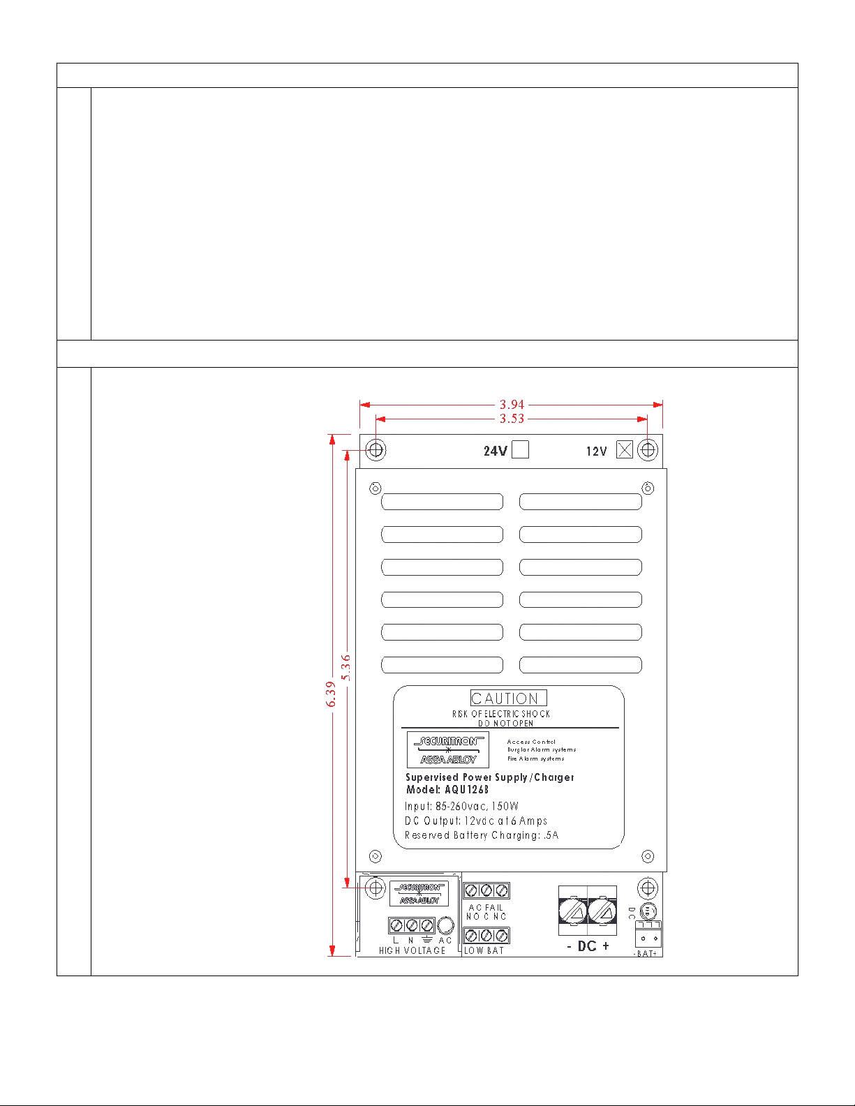
Physical Size:
Board: 3 15/16” x 6 3/8” x 2 3/8”
Mounting: : 3 9/16” x 5 3/8”
Weight*
AQU126B
1.5 lbs
Input Voltage Operating
Range
110-240VAC
47-63Hz
Maximum Output Voltage
72 VA
6 Amps @ 12VDC (±10%)
Continuous Output Voltage:
60VA
5 Amps @ 12VDC ((±10%)
Voltage Range:
9.8 -13.7 VDC/ 13.65V typical
Frequency
27KHz
Operating
Temperature
0ºF to 130ºF
[-17 to 54ºC]
Humidity
10% to 95% RH
For Indoor use
Recognized
Component:
UL294
UL603
UL1481
cUL
RoHS Compliant
1.800.624.5625 www.securitron.com
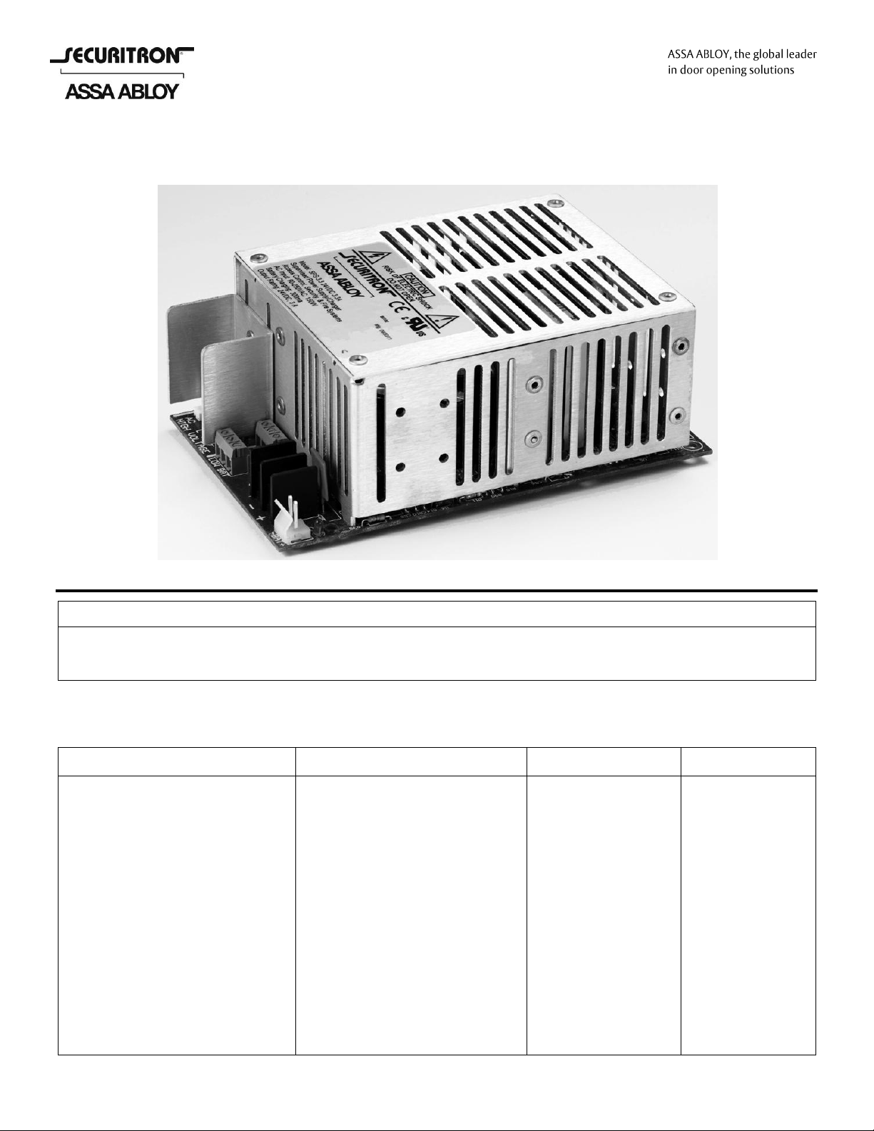
AccuPower AQU126B
Installation Instructions
*See Battery sizing guide on page 6.
© Copyright, 2013, all rights reserved Page 1 P/N 500-30035
Rev. A, 04/13
AccuPower AQU126B Specifications

Overview of AQU126B Series Power Module
The Securitron AccuPower AQU126B offers clean, steady and accurate power output for peak performance of access
control equipment plus flexibility unmatched by any power supply/battery charger on the market today.
Universal AC input with brownout tolerance to 60VAC
Tolerates and protects against input voltage fluctuations.
External LED AC power indicator
Form “ C“ contact for AC power fail notification
Dedicated voltage for battery charging even under full load
Low battery disconnect prevents deep discharge of batteries
PTC protection for Thermal Runaway and Current Overload Short Circuit and Reverse Battery protection -
will auto restart without removing load.
AQU126B and AQU126 provide a single output. The output can be divided into additional channels using any of the
optional power distribution boards: PDB4, PDB8, PDB-8F8R, PDB-8C8R, PDB-8C1R or PDB-1R.
Applications
The AQU126 Series can be used with electrified access control equipment in conjunction with access control systems
and fire/burglary systems including most electrified locking hardware and latches, card readers, keypads, electric
strikes, REX and motion detectors and more.
Pre-Installation Survey
Before installing the AQU126 Series, the mounting location should be determined and assessed for the following:
Availability of AC power service
Protection from vandalism and tampering
Sufficient clearance for air circulation and heat dispersal
CAUTION: Check with your local code inspectors to ensure your compliance with the National Electrical
Code (ANSI/NFPA 70), (Canadian Electrical Code for Canada) or equivalent and any additional licensing
and wiring requirements for your jurisdiction.
Rev. A, 04/13
Page 2 P/N 500-30035
A. Installing the Power Module
1.
Select mounting location so that AC input conduit can be aligned to maintain separation with DC power
outputs.
Ensure unit is mounted with sufficient airflow to prevent heat buildup.
IMPORTANT: AC Power input is not power limited. AC lines must be enclosed in approved
conduit. AC Input lines must be separated by at least ¼” from Class 2 power limited output
wires.
Mark board mounting hole locations and drill. Install mounting screws appropriate for the mounting
location, leaving enough hardware exposed to install standoffs. Install standoffs. Place starwheel on any
one of the three standoff locations corresponding to a mounting location on the board that has a metal ring.
Affix board to standoffs with provided metal screws.
IMPORTANT: User is responsible for observing all electrical and code requirement when
installing in self-provided enclosure or mounting location.
B. Make Electrical Connections
1.
Component Locations
Page 3 P/N 500-30035
Rev. A, 04/13
 Loading...