

Page 1
Installation Manual AQM-20 12vdc/24vdc Series Power Supplies
Securitron Magnalock Corporation
10027 S. 51st St., Ste. 102
Phoenix, AZ 85044
Doc.# 500-33010 Rev. B, Installation specifications subject to change without notice
Phone: (800) MAGLOCK
customercare@securitron.com
www.Securitron.com
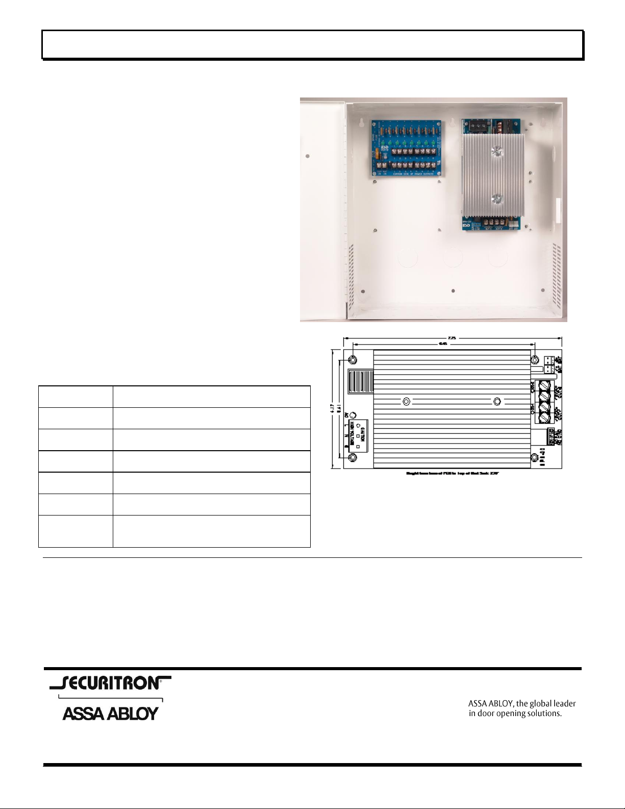
AQM20
20A 12/24 Power Supply/ Charger Module
mounted in a 14” x 14” metal Enclosure.
-8F
AQM20 with PDB-8F (fuses) Distribution
Module
-8C
AQM20 with PDB-8C (circuit breakers)
Distribution Module
-16F
AQM20 with two PDB-8F (fuses) Distribution
Modules
-16C
AQM20 with two PDB-8C (circuit breakers)
Distribution Modules
-8F8R
AQM20 with Smart Fan and PDB-8F8R
Supervised Distribution Module (Fuses)
-8C8R
AQM20 with Smart Fan and PDB-8C8R
Supervised Distribution Module (circuit
breakers)
AQM20 Supervised Power Supply/Charger 12vdc 20Amp/24vdc 10Amp
Life Time Warranty – Quality Manufactured in the USA
AQM20 Features:
The AQM20 has two 12vdc 8Amp rated Outputs
that can be connected in Parallel or Series to
provide 12vdc, 24vdc, or 12vdc & 24vdc.
Outputs 1 and 2 are fully isolated,
Independent Power Supplies.
Efficient Off-Line Switching Power Supply
Self Contained, No External Transformer
required
120/240VAC Selectable AC input
Extraordinary Brown Out Capability
Precise Battery Regulation for Lead Acid
Battery(s)
LED’s Indicate AC and DC Outputs 1 & 2
Relay Contacts Indicates AC Power Status
Battery Online, No Drop or Switch Over
with AC Power Fail
Auto Resetting circuit breaker for battery(s)
Over Current Protection with Reverse battery
protection
Electronic Power Limited and Short Circuit Protection
on each output
Each output has Thermal shut down with auto restart
Partial list of ordering examples:
Description
The AQM20 supervised power supply with battery
charger is two high powered, fully isolated, independent
power supplies enclosed in one small self contained
aluminum package. Each power supply, outputs 1 and
2, are a nominal 12vdc at 10 Amps with 12v lead acid
battery charger. These outputs can be used as
separate isolated 12vdc power supplies, or they can be
connected in parallel or series to provide 12vdc, 24vdc
or both 12vdc and 24vdc at the same time. When
outputs 1 & 2 are connected in parallel, the output is
13.75vdc at 20 Amps. When outputs 1 & 2 are
connected in series, the output is 27.5vdc at 10 Amps.
Because each output is independently regulated, you
may draw additional current from the 12V output 1,
Page 1 of 9
Page 2
AQM20 Series Installation Instructions
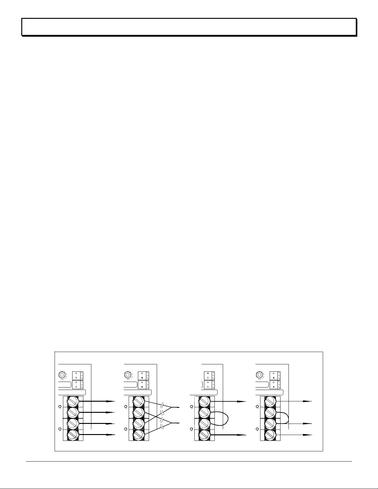
Output Terminal Block Configurations
-1+ -2+
BAT
BAT
-12VDC+
-12VDC+
OUT-1 OUT-2
DC-2
DC-1
-1+ -2+
BATBAT
-12VDC+-12VDC+
OUT-1 OUT-2
DC-2DC-1
-1+ -2+
BATBAT
-12VDC+
-12VDC+
OUT-1 OUT-2
DC-2
DC-1
12VDC
+
_
24VDC
8 Amps
_
+
_
+
+
12VDC
24VDC
COM
8A le s s 1 2 V a m p s
8A le s s 2 4 V a m p s
Fig 3 24VDC 8A Fig 4 12VDC & 24VDC
-1+ -2+
BATBAT
-12VDC+
-12VDC+
OUT-1 OUT-2
DC-2DC-1
Fig 1 2-12VDC 8A
12VDC 8A
12VDC 8A
+
+
_
_
Fig 2 1-12VDC 16A
16A
16" of 18awg
16" of 18awg
16" of 18awg
16" of 18awg
The 16" 18 gauge
wires shown below
are needed for the
outputs to share
the load when
connected in parallel
for full power.
while using the 24vdc output at the same time. The
12v current used has to be subtracted from the 10
Amps available on the 24vdc. Figures 1 - 4 illustrate
each of these four hookups for the SPS-20. Charging
two 12v batteries independently is also a very big
benefit for long battery life.
Specifications/Instructions
AC Input: L, N, G - 3P Terminal block
Safety Cover, snap or hinge is provided
L= Line, N= Neutral, and G = Ground
The G terminal must be connected to Earth Ground.
Optional 3 wire line cord P/N: ..................... HA-LC3SZIP
AC input/Hz/Watts default ...... 90-132vac/47-63Hz/400w
AC input/Hz/Watts (set 240) .. 133-250vac/47-63Hz/400w
UL evaluated at 60Hz 120/240vac
Caution: Never apply 240vac when AQM20 is set for
120vac this will void warrantee and damage unit.
The AC input default is 120vac. You can cut the PCB
trace marked “CUT 240” on the bottom of the PCB
under the input inductor above and toward the inside of
the AC input terminal block.
AC LED Indicator (Next to AC Input Terminal Strip)
The AC indicator is a bi-color green and red led. This
led off with AC at the terminals would indicate a blown
fuse link. A blown AC fuse link would indicate catastrophic
failure and must me returned to the factory for repair.
AC Status Output Relay: 3P Terminal block
AC fail “C” contacts ........................................ 2A/120vac
Three position AC fail terminal block marked “NO, C, NC” are
shown in the Normal, energized, AC ON condition.
DC OUTPUTS: 4P Terminal block (2 per output)
Output-1 & 2 continuous rating .............. 12vdc at 8A ea
Output 1 & 2 Typical Output Voltage .......... 13.72vdc ea
Load regulation no load to max ....................... .25%Typ
AC Line regulation 85-136vac/170-264vac ...... .03%Typ
Each Output ripple & noise at full load ............ 400mv pp
Current Overload Short Circuit Protection .............. Yes
Thermal runaway Protection .................................... Yes
Page 2 of 9
Current Overload and Thermal shutdown will autorestart without removing load.
Ambient operating temperature range .. -30oF to +130oF
Storage Temperature ............................. -60oF to 190oF
Switching Frequency .......................................... 66KHz
DC LED Indicator (Adjacent to each output pair) ......... Red
Battery Standby
Two 12” battery cable assemblies that plug from
AQM20 to battery are provided. Red (+) 12vdc,
Black (–)Neg.
Optional 36” battery cable (1) P/N: ............... WA-36IBAT
-Battery(s), any type of lead acid .......... 12v 4AH-100AH
Battery(s) recharge1 & 2 ................ 13.72vdc at 2A max
Battery(s) 1 & 2 recharge PTC self resetting ......... 1.04A
Battery(s) 1 & 2 discharge PTC self resetting ............ 8A
Battery)s) 1 & 2 Reverse hookup protection ............. Yes
In standby mode each battery is limited to 8 Amps of
continuous current. When both outputs are connected
in parallel, and standby current will be greater than 8
Amps, you must use 2 batteries connecting one to
battery 1 and one to battery 2. Paralleling (2) battery
cables to (1) battery will not double the current.
Review application note 3, Battery Standby table to
calculate battery size.
To estimate the recharge time in hours for depleted
battery(s), multiply the AH rating times 1.2. (AH x 1.2).
As an example, 2 12v 10AH batteries would take about
12 hours to re-charge.
Physical
AQM20 Module Dimensions .. 7.75”L x 4.17”W x 3.23”H
Height includes 7/16” standoffs
Mounting Holes Center to Center ........ 6.45”W x 3.41”H
AQM20 module only Weight ................................ 2.4lbs.
AQM20 (in Large enclosure) ................ 14” x 14” x 4.75”
AQM20Weight with enclosure ............................. 11.4lbs
Approvals
AQM20 meets requirements of . UL1950 3rd & EN60950
AQM20 is UL R/C .................................... UL603, UL294
AQM20 Installation Instruction: Doc.# 500-33010 Rev. B
Page 3
AQM20 Series Installation Instructions
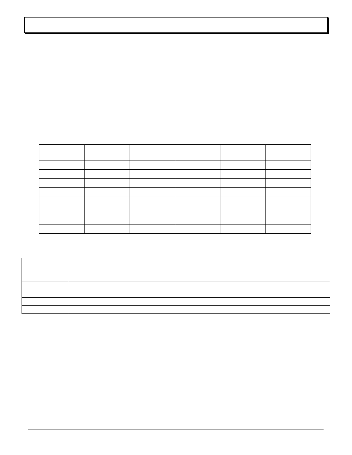
Total Output
Amps
4Ah Battery
Standby
7Ah Battery
Standby
12Ah Battery
Standby
24Ah
Standby
40Ah
Standby
.5A
5.5 Hrs
12 Hrs
20 Hrs
40 Hrs
65 Hrs
1A
2.5 Hrs
5 Hrs
9 Hrs
19 Hrs
32 Hrs
1.3A
2 Hrs
4 Hrs
7.2 Hrs
15.5 Hrs
24 Hrs
2A
1 Hrs
2 Hrs
5 Hrs
10 Hrs
15 Hrs
3A
.5 Hrs
1 Hrs
3 Hrs
6 Hrs
9.5 Hrs
4A
.5 Hrs
.8 Hrs
2 Hrs
4 Hrs
8 Hrs
5A
NA
.6 Hrs
1.4 Hrs
3 Hrs
7 Hrs
6A
NA
.4 Hrs
1 Hrs
2 Hrs
4 Hrs
Part Number
Description
AQM20
AQM20 Power Supply Charger Module Mounted in a 14” x 14” x 4.75” Enclosure
AQM20-8F
AQM20 with PDB-8F (fuses) Distribution Module
AQM20-8C
AQM20 with PDB-8C (circuit breakers) Distribution Module
AQM20-16F
AQM20 with two PDB-8F (fuses) Distribution Modules
AQM20-16C
AQM20 with two PDB-8C (circuit breakers) Distribution Modules
AQM20-8F8R
AQM20 with Smart Fan and PDB-8F8R Supervised Distribution Module (Fuses)
Maintenance
The power supply and stand by battery(s) should be tested at least once a year as follows:
1. Check LED’s for normal state. AC ON Green, DC #1 ON Red, and DC #2 ON Red.
2. Check output voltage with normal load. DC Output #1 and DC Output #2 should read between 13.60 and
13.80vdc.
3. Disconnect AC input. AC LED should be off, DC Output LED’s #1 and #2 should be ON.
4. Check DC Outputs #1 and #2 to be above 12.0vdc. This checks standby batteries to be operational. Sealed
lead acid batteries have a typical life of 3 to 5 years.
5. Re Apply AC and verify AC LED ON.
Battery Selection
The table below shows typical standby time in hours for various loads and batteries. The table works for either
12vdc or 24vdc. The AQM20 was evaluated at UL with a 7AH sealed lead acid battery with a 1 hour stand by.
Approximate Battery Standby Time Table with a reserve of 3 Amps for 5 minutes for Alarm
The recharge table below gives approximate recharge times for different loads and battery sizes. The table is based on
batteries depleted to battery cut-off and recharged back to approximately 90% capacity.
Ordering Guide with fuse sizes
CAUTION Reduce the risk of fire replace fuses as marked
Note: Keep a minimum space of ¼” between Power Limited Outputs and non Power Limited wiring
Page 3 of 9
AQM20 Installation Instruction: Doc.# 500-33010 Rev. B
Page 4

AQM20 Series Installation Instructions
AQM20 Series Power Supplies
Due to the variations with AQM20, the power supplies are not pre-wired to the accessories.
AQM20 Series Instructions Doc.# 500-33010 Rev. B
Page 4 of 8
Page 5

AQM20 Series Installation Instructions
Specifications
Input Voltage ..................... 10.5 to 12.4vdc or 22.7 to 25.2vdc
Output Voltage ............................... virtually the same as Input
Current, Typical, with No Output Load .................... 90-160mA
Outputs 1–8 continuous duty each ......................... 1.23 Amps
Voltage Trigger .......................... 20% < Input min. 30vdc max.
Voltage Trigger isolation ............................................... Optical
EOL (End of Line) Trigger ...................... Trip +-50% of 2.2K Ω
Transfer Relay Contacts ............................................ 15Amps
Trouble Form C Contacts .................... 2A 120vac/1A 220vac
Triggered Form C Contacts .................. 2A 120vac/1A 220vac
UL Approvals
UL 294 – Access Control System Unit
UL 603 – Power supplies for Use with Burglar-Alarm Systems
ULC S318-96 – Power supplies for Burglar Alarm Systems
ULC S533-02 – Standard for Egress Door Securing and
Releasing Devices
PDB-8F-MMM-FFF
8 Fused Outputs with ATO Main/power pull fuse,
status LED’s and 1500 watt surge protector.
PDB-8C-MMM-CCC
8 PTC Circuit Breaker Outputs with ATO Main/power
pull fuse, status LED’s and 1500 watt surge protector.
FFF
Fuse Options
FFF = Fuse Rating in Amps (x.xx) standard 3agc Size:
(050 = 500ma); (100 = 1A); (200 = 2A);
(300 = 3A); (400 = 4A); (500 = 5A)
CCC
Circuit Breaker
options
CCC = PTC part number equaling the holding current
in Amps at UL rating 50C:
(090 = .7A); (135 = 1.04A); (160 = 1.23A);
(185 = 1.42A); (250 = 1.93A); (400 = 3.08A);
(500 = 3.85A); (600 = 4.62A)
MMM
Main Fuse options
MMM = Main Fuse Rating in Amps (xx.x) – Standard
Automotive ATO Size:
(050 = 5A); (075 = 7.5A); (100 = 10A);
(150 = 15A); (200 = 20A); (250 = 25A)
PDB-8F
PDB-8C
UL 294 – Access
Control System Unit
UL 603 – Power
Supplies for Use with
Burglar-Alarm
Systems
ULC S318-96 – Power
supplies for Burglar
Alarm Systems
ULC S533-02 –
Standard for Egress
Door Securing and
Releasing Devices
PDB-8C / PDB-8F
Multi Output
Low Voltage Power Distribution Modules
Life Time Warranty
Features/Specifications:
Converts a single AC or DC (12 or 24v) Input to 8 or 16 protected outputs with
fuses or circuit breakers
1500 Watt surge protection on PDB-8F Input rated 22 Amps @ 32 volts AC or
DC
All PTC circuit breaker ratings are holding current at 130oF per UL Standards
Main Power Green/Red LED Indicates AC, DC or Reversed DC Input on PDB-
8 and PDB-9
Each output has a green status LED indictor
Current Draw is 6ma max per LED
Main Fuse / Power Pull is standard ATO Automotive size on PDB-8
ON / OFF Power Switch on PDB-4F
Circuit Breaker Models with Rated Output 1.42 Amps or below are Power
Limited
PDB-8F & PDB-8C are As configured in UL listed
products.
PDF-8F, & PDB-8C are UL listed Sub Assemblies As configured in
UL listed products
suitable for Access Control and Burglar alarm systems
All Input Terminal blocks and output terminal blocks on the PDB-8F module
are rated 40A with a wire range of 10 – 18AWG
Size: PDB-8F 3.87”H x 4.84”W x 1”D Mounting: 3.41”H x 4.49”W
Quality Manufactured in the USA
Custom Order details NOT UL LISTED
AQM20 Series Instructions Doc.# 500-33010 Rev. B
Page 5 of 9
Page 6

AQM20 Series Installation Instructions
PDB-8F8R Power Distribution for Access Control with Fire Interface module
Controls and Distributes Power with 8 Control Relays with an EOL Fire trigger Interface
Power Interface for Access Control, CCTV, Fire, HVAC, Elevator,
and general low voltage system control
Note: Fire, HVAC and Elevator Control has not been evaluated by UL
Features:
8 Heavy duty Relays with individual Inputs and Status LED’s
Each Relay Input can be Activated from Low Current Open
Collector, Normally Closed or Normally Open Switch
EOL End of Line Resistor Fire Interface Master Trigger de-
energizes all Output Relays that are Enabled
Universal 11 – 27.5Vdc power input
Available with Fuses or PTC Circuit Breakers
Note: Only the 500mA fuse version of the board has been
evaluated by UL
Note: The outputs of the PDB-8F8Rare power limited when
connected to the AQD3 power-Limited power supply
Each Output may be Individually Configured for:
o Fire Trigger (FT) Enabled or (FTD) Disabled
o FUSE model can provide optional Dry Contacts
o N/O or N/C Option Configures the Relay Switched
Output
Each Output 1-8 has a protected, continuous Output and a
Relay controlled Output
TRG LED Green Indicates Trigger Status
Control Power and Main Lock Power may be Isolated
(Separate Power Supplies) at Users Option
Note: Dual/separate power source configuration has not been
evaluated by UL and cannot be configured for UL Listed
products
All Terminal Blocks are Pluggable by Channel & Function
Made in the USA with a Lifetime Warranty
Description / Instructions
The PDB-8F8Ris a versatile, compact way to distribute and
control power for Access Control Systems with Fire Alarm
Interface. The PDB-8F8Ris an 8 position power
distribution board with individual Relays with input (IN)
control for each output (OUT). An EOL resistor trigger
input (TRIG), will force all output relays to de-energize that
are selected (FT). In a typical installation, the TRIG would
be connected to a Fire Alarm panel via a set of contacts.
When the Fire Alarm trips, all enabled relays would be
forced to be de-energized to unlock electric doors, shut
down air systems, and or return elevators to ground floor.
Input / Output Terminals, Jumpers and LED
Details and Specifications
Control Power (- CONTR +) Two position un-pluggable
terminal block is used to power the coils of the relays. The
control voltage must be between 11 and 27.5 Vdc. Each
relay energized will draw 20ma of current. By default,
Control Power and Main Power are connected together
with jumpers J1 & J2 so no connection would be made
here unless you were using Dual/separate power as
described below. Note Dual/separate power source
configuration has not been evaluated by UL and cannot be
configured for UL Listed products.
Main Power (- POWER +) Two position un-pluggable
terminal block provides the power to the outputs to be
distributed and power to Control through J1 & J2. In a
normal application the Power must be between 11 and
27.5 Vdc and would be connected here.
Dual/Separate Power J1 & J2 Jumpers Note
Dual/separate power source configuration has not been
evaluated by UL and cannot be configured for UL Listed
products. J1 Connects (-) Power to (-) Control, J2
Connects (+) Power to (+) Control. By default J1 & J2 are
S
AQM20 Series Instructions Doc.# 500-33010 Rev. B
Page 6 of 9
Page 7

AQM20 Series Installation Instructions
connected together. When J1 & J2 are cut, you must
supply 11 to 27.5Vdc to Control power, then you may
connect any voltage to 32V AC or DC to the Main Power
Terminals. See Dual/Separate Power application figure
below.
Inputs (1-8 IN C) Eight, two position un-pluggable terminal
blocks. When IN & C are shorted together, the like number
output relay will energize. Each relay can also be
energized by an open collector that is common to the
control power, sinking 20ma for each input. Each of the
C’s (common) are connected to control negative power.
Input LED’s (1-8) Whenever an input is active (relay
energized) the associated input red LED will illuminate.
FDT/FT (1-8) Jumpers - These are three pin headers
adjacent to each fuse with a shunt with handle that shorts
the center pin to FTD or FT.
FTD = Fire Trigger Disabled - When selected, the
Trigger will not effect that output.
FT = Fire Trigger – When selected Triggering will force
that Input Relay to De-Energize.
Dry/Wet Option (1-8 Fuse Models) Through a Fuse, the
(+ Power) is connected to the swing arm of each Relay to
distribute power to its output. Removing the Fuse,
removes the power from the relay. The (+) now becomes
the Common Swing Arm and the “O” is the N/O or N/C
contact as selected with jumper.
Outputs (1-8 OUTPUT C, +, O) Eight, Three position un-
pluggable terminal blocks. “C” is Power Common and is
connected to (- power). “+” is connected to fused (+power)
and the relay swing arm. “O” is the relay switched output
as selected with N/O or N/C selector jumper
Output Relay Contacts Selector (1-8 NC/NO) Jumpers
These 3 pin headers with shunt selectors are located just
above each output which selects whether the N/C or N/O
contacts are connected to the “O” switched output terminal.
With N/C selected, output would be normally ON, or
connected to swing arm. With N/O selected, output would
turn ON, or close when input is activated. Fire Alarm
Interface Trigger (2.2K EOL TRIG) Two position unpluggable terminal block. This input must see the 2.2K
ohm EOL (End Of Line) resistor to be in the normal
condition. The EOL is to be placed in a Listed fire alarm
panel. See Fig 1 illustrating that shorting or opening the
EOL will cause the PDB-8F8R to trigger.
TRIG LED (TRIG) Green LED normally ON. Whenever the
Trigger is active the LED will be OFF.
Ordering Information
PDB-8F8R “ACI” module only with 500ma Fuses Note:
Only the 500ma fuse version of the board has been
evaluated by UL No other fuse size or PTC’s can be used
with a AQD3 .
Specifications
Control (-contr+) ........................... 11–27.5Vdc @ 160mA
Normally no connection is made here. Note: You must add
this current to your total device load calculations to be sure
your load will be within the rating of the power supply as
configured
Main Power (-power+) .................................... 11-27.5Vdc
Note: Must cut J1 & J2 when not using 11-27Vdc power
See Dual/Separate power source configuration Note
Dual/separate power source configuration has not been
evaluated by UL and cannot be configured for UL Listed
products.
Total Amps would be equal to the total current of the
outputs load plus the module draw of 160ma
Fused/Wet Outputs (12v operation):
Max. Output Current .................. 330mA,12V (each output)
2.64 A (total all outputs)
Fused/Wet Outputs (24V (each output):
Max. Output Current .............. 155mA, 24V (each output):
1.24 A (total all outputs)
Dry Outputs:
Max. Output Current ............................................ 3A, 30V
As evaluated with UL with 500ma fuses
Terminal blocks un-pluggable ... 5mm spacing 14–22 awg
Fused Outputs 1-8 .............................................. 500mA
Littlefuse P/N 217.500 20mm replacement
The fused outputs of the PDB-8F8Rare power limited when
connected to the AQD3 power-Limited power supply
Output Relays 1-8 Dry Contacts are not to exceed
................................................................... 7A or 100VA
Trigger Input .................................................... 2.2K EOL
Operating Temperature .................................. 0o to +49oC
Mounting Holes ......................................... (4) 3.4” x 4.5”
Module Size: ................................ 4.82”w x 3.84h x 1.4”d
Weight: ...................................................................... 8oz
Mounting Note: Secure 4, #6-32 female/female hex
standoffs 7/16” long onto 4, #6-32 studs provided in
distribution option space to the right of AQD3 inside E1485 cabinet back. Place PDB-8F8Ron stand offs with
input terminals on top. Secure module with 4, #6-32 x ¼”
pan head screws. No metal hardware should be larger
than .28” in Diameter.
Note: All interconnected devices must be UL Listed.
UL Approvals for PDB-8F8R
UL 294 Access Control System Unit
AQM20 Series Instructions Doc.# 500-33010 Rev.B
Page 7 of 9
Page 8

AQM20 Series Installation Instructions
PDB-8F8R Typical Applications
Single Power Source Application Fig 1
Dual/Separate Power Supplies Fig 3
AQM20 Series Instructions Doc.# 500-33010 Rev.B
Page 8 of 9
 Loading...