

Page 1
AQE-Series
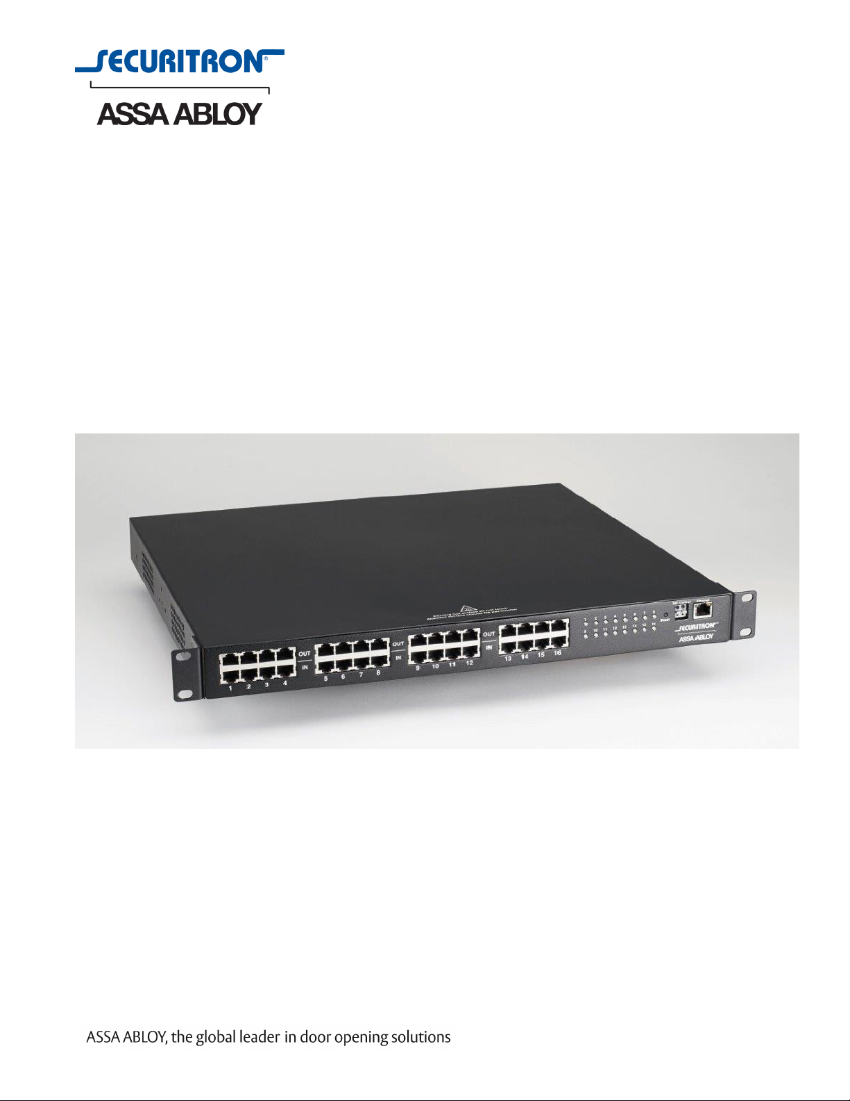
Multi-port Power Over Ethernet Midspan Injector
Installation Manual
500-33600, Rev. A
Page 2

Table of Contents
Notes and Warnings ......................................iii
Symbol Definitions ............................................................ iii
Warnings.................................................................... iii
Regulatory Information ......................................................... iii
Conventions Used Within this Manual.............................................. iii
Introduction............................................iv
Product Description ........................................................... iv
The AQE Series ............................................................... iv
Section 1 – Installation ....................................1
1.1 Mounting the AQE Rack Mount Supply into a Standard 19" Rack .......................1
1.2 AQE Rackmount Power Supply Overview.........................................2
Section 2 – Initial Configuration .............................. 4
2.1 Preparing to configure the AQE ................................................4
2.2 Logging into AQE Power Supply Control Center for the first time ......................4
2.3 Configuring the TCP/IP Settings................................................5
2.4 Configuring the Administration Settings .........................................6
2.5 Configuring the SNMP Settings ................................................6
2.6 Configuring the Email Settings .................................................7
2.7 The Programming Page.......................................................8
Section 3 – Using the AQE ..................................9
3.1 Viewing System Parameters on the AQE Home Page ................................9
3.2 The Tools page ............................................................11
Appendix 1 – Software Agreement and Warranty Statement .......... 12
ii
500-33600, Rev. A
Page 3

Notes and Warnings
Symbol Definitions
The following symbols are used in the Warnings section
below:
This symbol alerts the installer of shock hazards
h
i
h
h
i
i
h
within the enclosure. Service should only be
performed by qualified service personnel.
This symbol alerts the installer of important
information intended to help the installer avoid
personal injury or property damage.
Warnings
Installation and service should be performed only
by qualified service personnel and should conform
to all local codes.
To reduce the risk of electric shock or fire, this
equipment must not be exposed to rain or
moisture.
This equipment shall be installed in a manner which
prevents unintentional operation by employees,
cleaning personnel, or others working in the
premises; by falling objects; customers; building
vibration; or similar causes.
This equipment is not intended for use within the
patient care areas of a health care facility.
Fuses shall only be replaced with the same type and
rating as indicated in the specifications section of
this manual.
Regulatory Information
The equipment discussed within this manual has been
tested to the following standards:
• EN60950 EN55022 CLASS A EN55024
• CSA C22.2 #60950
FCC Information
NOTE: This equipment has been tested and found to
comply with the limits for a Class A digital device,
pursuant to Part 15 of the FCC Rules. These limits are
designed to provide reasonable protection against harmful
interference when the equipment is operated in a
commercial environment. This equipment generates, uses,
and can radiate radio frequency energy and, if not installed
and used in accordance with the instruction manual, may
cause harmful interference to radio communications.
Operation of this equipment in a residential area is likely to
cause harmful interference in which case the user will be
required to correct the interference at his own expense.
Conventions Used Within this Manual
Positional information (e.g., top, bottom, up, down, left,
right) is referenced with the board or enclosure in the
orientation shown in the illustrations in this manual.
To prevent impaired operation, all wiring is ensured
i
i
to be routed and secured to prevent accidental
open or short circuit conditions.
The system and any batteries (if used) should
be tested at least once per year to ensure proper
operation.
iii
500-33600, Rev. A
Page 4

Introduction
Product Description
The AQE series of multi-port Power over Ethernet (PoE)
midspan injectors are designed to provide power to
PoE-compatible Internet Protocol (IP) devices such as IP
surveillance cameras, IP phones, door locks, infrared (IR)
illuminators and other PoE-compatible access control edge
devices. The AQE-series products provide 32 watts (W)
of power per port and are compliant with the Institute of
Electrical and Electronics Engineers (IEEE) Standard 802.3,
"Ethernet."
The chart below shows the list of models in the AQE product
family:
The AQE Series
AQE Model No. Description Notes
AQE500R 16 port
32W per port
540W total
Managed midspan injector
Programmable
port priority
The illustration below shows the model numbering
convention of the AQE series using an example model
number. AQE indicates the model series. The number “500”
indicates a total of 500 Watts nominal output power available.
Currently, 500W and 250W models are available. The letter
“R” indicates rack mount, which is present on all models.
AQE 500 R
Product series
Total output power
Example AQE series model number
Specifications
Input voltage range 100 – 230 VAC
Input frequency 47 – 63 Hz
Max input current (500W model) 9.0 A
Max input current (250W model) 4.5 A
Power factor > 0.92
Rack Mount
AQE250R 16 port
32W per port
270W total
Managed midspan injector
Programmable
port priority
iv
500-33600, Rev. A
Page 5
Section 1 – Installation
The following pages cover the installation of the AQE-series rack-mountable PoE power supplies.
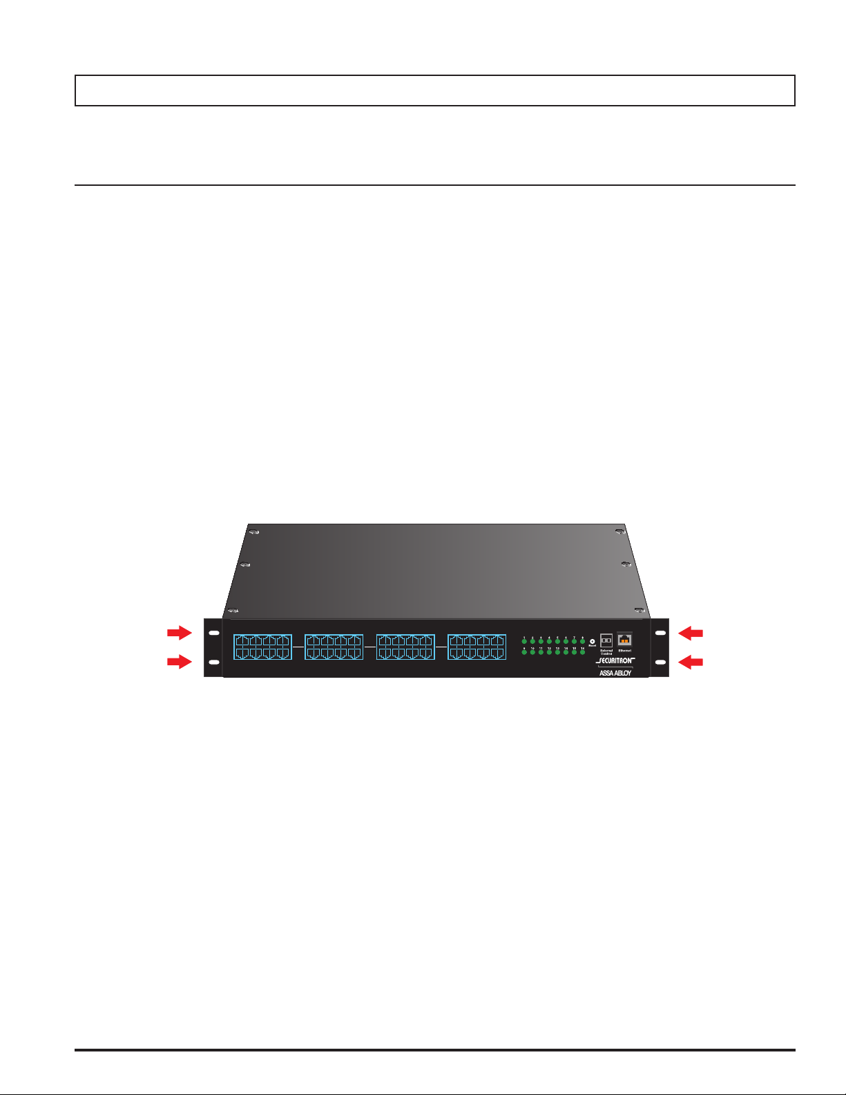
1.1 Mounting the AQE Rack Mount Supply into a Standard 19" Rack
Use the following procedure when mounting an AQE-series
supply into a standard Electronics Industry Alliance (EIA)
19" equipment rack.
1. If not already completed, securely MOUNT the included
ears to the front of the enclosure sides using the eight
included countersunk screws (four per ear).
2. LOCATE the rack-mounting holes in the ears of the
enclosure. (Figure 1)
3. SLIDE the enclosure into an open 1U location in the EIA
rack
4. CENTER the enclosure in the rack and SECURE with
the four provided 10-32 x 3/4" screws.
NOTE: Rails or other appropriate support for heavy
enclosures shall be used. Heavier components shall be
kept near the bottom of the rack to reduce the risk of
toppling of a top-heavy rack.
OUT
1 2 3 4 5 6 7 8 9 10 11 12 13 14 15 16
IN
OUT
IN
Figure 1. The Enclosure Mounting Holes
OUT
IN
1
500-33600, Rev. A
Page 6
1.2 AQE Rackmount Power Supply Overview
1
2
345
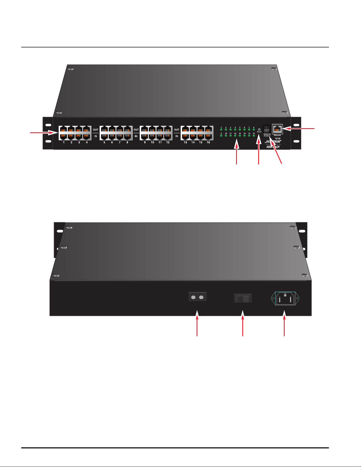
Figure 2: AQE Front View
+–
h
No user serviceable parts inside
refer servicing to qualified service personnel
Aucune pièce interne ne peut être réparer
Demandez l’assistance d’un technicien qualifié
External DC
On / Off
AC Power
Figure 3: AQE Rear View
2
500-33600, Rev. A
Page 7

The following are basic descriptions. Refer to the appropriate section for more detailed information.
PoE Input / Output (IN / OUT)
1
There sixteen RJ45 jack pairs (top and bottom pair) labeled
sequentially. For each pair, the bottom jack is for network
data input. The top jack is the data and power output.
CONNECT your data only cables to the bottom row of the
RJ45 jacks (from a network switch, video server, etc.).
CONNECT the top jacks to the corresponding PoE compatible
devices (e.g., IP cameras).
Ethernet Input (Ethernet)
2
This port allows users to monitor and control the AQE
multi-port midspan injector through a computer, over a
Local Area Network (LAN) or the Internet. The management
software AQE Power Supply Control Center is web browser
based. You may connect a Personal Computer (PC) directly
to this Ethernet port, or via LAN/Internet.
External Control (External Control)
3
This connector allows an external trigger voltage to shutdown
selected PoE outputs (programmed by user via the AQE
Power Supply Control Center management software).
The trigger voltage is 5 to 24V, AC or DC.
Reset Button (Reset)
4
Pressing the recessed reset button with a pin for 6 seconds
will reset the IP address and password to the factory default
values.
The factory default IP address is: 192.168.1.9
The factory default user name is: admin
The factory default password is: admin
Front Panel LEDs (1-16)
5
The 16 front panel LEDs (labeled 1 through 16) indicate the
port status of the corresponding PoE channels. When the
output is connected to a valid PoE Powered Device (PD)
within the specified current limit, the LED will be green,
indicating normal operation. When there is a fault condition,
such as when no PD is connected to that port, the LED will
be yellow.
The LED will be turned off if the corresponding port is
disabled by the AQE Power Supply Control Center software.
AC Line Input (AC Power)
6
This is the connector for the AC line cord.
PLUG the included computer-style line cord into this
connector.
CONNECT the other end of the cord to the power strip inside
the rack or another suitable AC power receptacle. The AQE
series accepts 120–230 VAC ONLY.
Main AC Power Switch / Circuit Breaker (On/Off)
7
This is the main AC power switch for the AQE. This switch
lights when power is on and also has a built-in circuit breaker
rated at 15 Amperes (A).
If the circuit breaker trips, RESET it by cycling the switch to
off then back to on.
External DC Voltage Input (External DC +/-)
8
This input may be used to either power the AQE via an
external 50 VDC supply or to provide battery backup to the
AQE. The “External DC” input is reverse polarity protected. See
below for details:
To Use Battery Backup
Connect AC power to the AQE unit as normal. In addition,
connect a 48V nominal battery set to the “External DC”
connector, using the battery cable supplied.
To Use an External 50 VDC Supply
Connect a 50V power supply to the “External DC” connector
at the rear. The ratings requirements for the DC power supply
are given below:
Input voltage range 44 – 57 VDC
Max input current (500W model) 14.0 A
Max input current (250W model) 7.0 A
Note that if both AC and DC power sources are connected to
the unit at the same time, the AC source will supply the power
to the output ports. The external DC source will not supply the
outputs unless the AC source is missing or the power switch
is turned off.
LED Status Status
Green Normal Operation
Yellow (Fault)
Off Port disabled
When the AQE is first powered, these LEDs will light yellow
in sequence (1-16) six times as the unit performs a self-test.
No Powered Device connected or fault
condition present
3
500-33600, Rev. A
Page 8

Section 2 –
The AQE Power Supply Control Center management software allows users to configure, as well as monitor and control each
output port of the AQE series midspan injector. It is embedded and web browser based and does not require the installation
of any dedicated software on the user's PC. Any PC with an Ethernet port and a common web browser may be used to access
Initial Configuration
2.1 Preparing to configure the AQE
In order to perform the initial configuration of the AQE, you
will need the following:
• A computer (PC or Mac) set to a static IP address
in the subnet 192.168.1.xxx, where xxx is a subnet
address (0 to 255) not being used by any other
device on the network. DO NOT USE 192.168.1.9 or
the final IP address you will be using for the AQE.
(See Figure 4.)
• A web browser installed on the computer.
• A CAT5 or higher Ethernet cable long enough to reach
between the computer and the AQE's Ethernet port.
• The AQE must be powered. After powering the AQE,
WAIT for the AQE to initialize. When ready, the port
LEDs will be lit steady.
After the AQE is powered and initialized, CONNECT the
Ethernet cable between the Ethernet ports of the AQE and
computer. The green LED on the Ethernet port of the AQE
should light. A few seconds later, the yellow LED will begin
flashing.
2.2 Logging into AQE Power Supply Control Center
for the first time
From the factory, the AQE is preset with the following settings:
• IP Address: 192.168.1.9
• Username: admin
• Password: admin
OPEN a browser on the computer and enter "192.168.1.9"
into the address bar (not in a search bar - you may need
to disable a "search from the address bar" setting in your
browser, if enabled). A window will appear asking for
authentication (See Figure 5). ENTER "admin" for both the
user name and password. The AQE Home Page should
appear (See Figure 6).
Figure 4: Example of a PC Ethernet port setting window
Figure 5: AQE Power Supply Control Center user login dialog box
4
500-33600, Rev. A
Page 9

Figure 6: AQE Power Supply Control Center opening (HOME) page
2.3 Configuring the TCP/IP Settings
In the orange menu bar at the top of the browser screen,
click the "Configure" link. Figure 7 shows the Configure page.
At the top left of the Configure page is the “TCP/IP Setting”
area. The settings in this area include:
Site ID
Entered by user. ENTER any meaningful name to identify
the AQE midspan unit. This name will be displayed on
the HOME page.
IP Address
The factory default IP address is set to 192.168.1.9. This
address may be changed to any valid IP address. SET the
first three values of the IP address to match the domain
of the network to which the AQE will be connected. SET
the final value to a number between 0 and 255 which is
not being used by any other device on the subnet. In the
event the IP address is later forgotten, PRESS the “Reset”
button on the front panel of the AQE for 6 seconds and the
IP address, default user name, and default password will be
reset to factory default values.
Net Mask
Should typically be set to 255.255.255.0
MAC address
The MAC Address is factory set and is not programmable
by the user.
Gateway IP
The default gateway is 192.168.1.1. This value may be
changed by the user - consult with your IT department
for more information.
DNS0, DNS1
The default value for DNS0 and DNS1 are 192.168.1.1.
These values may be changed by the user - consult with
your IT department for more information.
5
500-33600, Rev. A
Page 10

Enable DHCP
Normally, this option is left unchecked, however in some
cases you may want to allow the network to assign an IP
address to the AQE. However, please note that once you
select this option, you will need a network scanning
tool to find the AQE's IP address before you will be able
to log into the AQE and that the IP address of the AQE
may change periodically.
You must click the “Submit” button at the bottom right of this
area to save the changes in this section. The new setting will
take effect after the AQE product is power cycled, or rebooted.
2.4 Configuring the Administration Settings
On the top right of the Configure page is the “Administration
Setting” area. The settings in this area include:
Admin User Password
The default password for the admin account is admin. This
may be changed to any password of at least 5 characters.
ENTER the new password into the "Admin User Password"
field. If changing the password, ENTER it again into the
"Verify Admin Password" field. These two fields must match
in order to successfully change the password. CLICK the
"Submit" button - a popup message will confirm a successful
password change. When you leave the configure page, the
AQE will ask you to re-log in.
Insert Date
ENTER the correct date in the specified value field. It
should be noted that the format is YYYY-MM-DD. For
example, for February, you should enter “02” not “2”.
Insert Time
ENTER the correct time in the specified field. The format
is HH:MM:SS.
CLICK the “Submit” button to save the time and date
settings.
2.5 Configuring the SNMP Settings
In the SNMP Setting block, under the "Basic" heading, SET
Community to "public" and SET Location to a meaningful
name of your choice. This entry will help you identify
the specific AQE when multiple AQEs are installed on
the same subnet. In the example, "LSP" is entered. This
entry will be read by an SNMP system as "syslocation,"
OID .1.3.6.1.2.1.1.6. The default port for SNMP is Port 161.
Be sure to open the SNMP port if accessing SNMP outside
your firewall. CLICK the "Submit" button at the bottom of the
"Basic" section to save the settings, otherwise you will lose
Figure 7: Top half of the AQE Power Supply Control Center Configure page
6
500-33600, Rev. A
Page 11

the settings. These settings will take effect after a reboot of
the AQE.
The "Security Name" section of the SNMP Setting block
allows you to grant only specified computers (by IP
address) SNMP v1 and v2 access. Since v1 and v2 do not
have password protection, the Security Name settings add
security to v1 and v2 access. The web server is password
protected and a user must have the web server password
in order to setup a computer in the Security Name settings
and gain v1 and v2 access.
The example sets up computers connected to a subnet
to gain SNMP v1 and v2 access. The subnet is named
"mynetwork" and the source network is 192.168.1.xxx. It
should be noted that the last part of the IP address needs
to be replaced with "0/24" to allow all computers in the
192.168.1.xxx subnet to access the AQE with SNMP v1 and
v2.
Sender's Email
This is the email address which the AQE will use to send
emails.
Sender Email Password
This is the password associated with the Sender's Email
account.
TLS
CHECK this box if your email provider requires TLS or SSL
encryption.
SMTP Port #
ENTER the port number required by your email provider for
sending email. Usually this is "25".
Authentication
CHOOSE the proper authentication method for your email
provider from the drop-down list. Usually, this is "login".
Multiple source networks can be added to the Security
Name Setting block. CLICK the "Submit" button to save the
settings. The settings will take effect after a reboot of the
AQE.
The "V3 User" section of the SNMP Setting block allows for
a user to set up an SNMP v3 user name and password. With
a user name and password, the AQE may be accessed from
anywhere via the internet by using the SNMP v3 protocol.
No security name setup is required for v3 users and
multiple v3 users may be set up in the same table. CLICK
the "Submit" button to save the settings, which will take
effect after rebooting the AQE.
2.6 Configuring the Email Settings
The AQE can be configured to send email alerts on
user-specified conditions and periodic status reports.
Underneath the SNMP Setting block on the Configure page
is the Email Setting block (See Figure 8).
Under "Receive Addresses", the email address or addresses
to receive the alerts and reports should be entered. Up to
four recipient email addresses may be entered.
Send Period
Selects how often the NPR sends a regular email status
report. The period can vary from 1 hour to 6 months or, if
you do not want the NPR to send periodic reports, SELECT
"Never". It should be noted that the "Send Period" setting
does not affect the sending of email alerts generated on
faults or events selected by the user, only the periodic
status report.
NOTE: Regarding Microsoft Exchange – By Default, Microsoft Exchange
will not accept SMTP connections. To use the AQE's email functions
through Microsoft Exchange, the Exchange service must be configured
to allow SMTP connections. Consult with the administrator of your
Microsoft Exchange Server.
TIP: Most mobile phone providers have an email address available which
will convert an email into an SMS text message. This email address is
usually in the form of: (the mobile phone number)@xxxxxx. Consult with
your mobile provider for more information. The CSV attachment will be
removed, since SMS text messages are not compatible with attachments.
Because of this, it is recommended that the SMS email be entered as an
ADDITIONAL "Receive Address" on the AQE, so that the CSV file will still
be available via regular email.
Under "Sender", the settings of the account to send the
emails should be entered. These settings include:
CLICK the "Submit" button to save the settings, which will
take effect after rebooting the AQE.
Sender SMTP Server
This is the address of the SMTP server for the email
provider. Consult with your email provider for this address.
7
500-33600, Rev. A
Page 12

Figure 8: Bottom half of the AQE Power Supply Control Center Configure page
2.7 The Programming Page
Figure 9 shows the Programming page of the AQE Power
Supply Control Center management software.
The programming page allows users to set optional upper
and lower limits for the measured voltage and current
of each port. If any of these limits are exceeded, and the
“E-Mail Alert” box is checked for the port, an email will be
sent to the address configured in Section 2.6 of this manual.
This email includes an attached CSV file containing all of the
data in the HOME page. NOTE: The email settings must be
configured properly. See Section 2.6 of this manual.
To enable upper and lower limit checking, CHECK the box
next to “Voltage & Current Limit Setting” at the top of the
screen. CHECK the “E-Mail Alert” box for any port to be
monitored and ENTER the lower and upper limits for that
port. CLICK the “Save” button to save the settings.
NOTE: The upper and lower limits entered must be within
the allowed range. For voltage limits, the range is 0 to 60V.
For current limits, the range is 0 to 638mA.
Figure 9: The Programming page of AQE Power Supply Control Center
8
500-33600, Rev. A
Page 13

Section 3 –
Using the AQE
3.1 Viewing System Parameters on the AQE Home Page
The Home Page is shown in Figure 10. To access the
Home Page, CLICK "Home" in the orange menu bar at the
top of the page.
The top of the home page shows general information:
Model Number
This field displays the model number of the AQE
being accessed. The model number in the example is
“AQE250R”.
Site ID
This field is a descriptive name for the AQE unit being
accessed and is set by the user on the Configure page.
Date and Time
This field shows the date and time as set up by the user in
the Configure page. The date and time can be adjusted by
time zone and is battery backed up via an internal battery.
Auto-refresh
CLICK the "Enable" button to turn on auto-refresh for the
home page. Auto Refresh automatically reloads the page
every five seconds to update the data shown. CLICK the
button again to disable Auto Refresh.
Below the general information area is the port information
and control area:
Port
This column lists the port numbers with a checkbox to
the left of each number. The port numbers in this column
refer the port numbers on the front panel of the AQE.
CLICK the checkboxes to select one or more ports for
enabling or disabling. CLICK the checkboxes again to
deselect the port.
Figure 10: Home page of AQE Power Supply Control Center
9
500-33600, Rev. A
Page 14

Priority
This column allows users to set a priority for each port.
For each port there is a corresponding priority drop-down
list where a priority between 0 and 15 can be selected
(where “0” is the highest priority and "15" is the lowest
priority). After the priorities are set, the "Save setting”
button at the bottom right of the HOME page must be
clicked to save the priority settings.
Class
This column displays the power class of each port. The
“power class” information is provided by the connected
Powered Device (such as a PoE compatible IP camera)
during the power interface between the PoE midspan
injector and the Powered Device. When a port is not
connected to a load (Powered Device), or when a port is
disabled, the class display shows “N/A”.
When the total power drawn from the AQE exceeds the
rated value (ex. 270W for the AQE250R), the lowest
priority ports will begin disabling to prevent the AQE from
overloading. NOTE: Each port can supply a maximum of
30W of power per the IEEE 802.3at standard provided
that the total power drawn does not exceed rated power
for the AQE model used.
NOTE: If two or more ports have the same priority
selected, the AQE will disable the lowest number port
first (i.e., Port 1 will disable, then Port 2 if both are set to
the same priority).
External Control
This column allows users to select which ports will be
controlled by the "External Control" input terminals on
the front panel of the AQE. When the External Control
terminals are activated (by an access control panel,
switch, or other device), the ports that are selected will
disable. After checking the ports, save the selection by
clicking the “Save setting” button at the bottom right of
the HOME page.
Device
This column allows the user to enter names for the PoE
compatible devices connected to each output port of the
AQE. The maximum length of the entry is 20 characters.
After entering the names, click the “Save setting” button
at the bottom of the HOME page.
Enable
This column shows the enable/disable state of each port.
If a port is enabled, the display shows “On”. If a port
is disabled, the display will show “Off”. See the Enable
and Disable button sections of this manual for more
information.
Status
This column displays the status of each output port.
When a port is normal (a Powered Device is drawing
power within the specified limits), the corresponding
status will display “Normal” with a green background. If
there are any fault conditions or the port is disabled by
the “External Control” signal, the corresponding status
will display “Fault” with a yellow background. If a port is
disabled by the AQE Power Supply Control Center GUI,
the corresponding status will display “Disabled” with a
grey background.
Underneath the data table, there are five colored buttons.
Their functions are described as follows:
Enable selected ports
Clicking this button enables any ports whose checkbox
in the "Port" column is checked. After the button is
clicked, any ports selected in the "Port" column will be
deselected.
Disable selected ports
Clicking this button disables any ports whose checkbox
in the "Port" column is checked. After the button is
clicked, any ports selected in the "Port" column will
be deselected. This function is useful for momentarily
cycling power to frozen PoE cameras or other devices.
Enable all ports
Clicking this button will enable all output ports of the
AQE midspan.
Disable all ports
Clicking this button will disable all output ports of the
AQE midspan.
Voltage
This column displays the measured PoE port output
voltage for each port in volts.
Current
This column displays the measured PoE port output
current for each port in milliamps.
Power
This column displays the power output of each PoE port
in watts.
Save setting
Clicking this button will save the settings in the “Ext.
Control” and “Device” columns.
10
500-33600, Rev. A
Page 15

3.2 The Tools page
Rebooting the AQE
Upgrading Firmware
The Upgrade Firmware section is at the top left of the
Tools page (See Figure 11). To upgrade the firmware,
first ENSURE that the new firmware file is available on
your computer, then CLICK the "Upgrade" button and the
Upgrade window will appear.
CLICK the "Browse..." button and locate the new firmware
file with the file extension ".bin" on your computer. Once
the file is selected, CLICK "Open". CLICK the "Download"
button to temporarily download the new firmware into the
RAM of the AQE. This process will take from 30 seconds
to one minute, depending on network speed and traffic
and the message box will display "Downloading...". Once
the firmware is loaded into the NPR's RAM, it can then be
burned to the processor in the AQE. VERIFY the correct
file name and CLICK the "Confirm" button to confirm the
upgrade. Next CLICK the "Burn" button to begin burning
the firmware to the AQE's processor. This process may
take up to 12 minutes - DO NOT REMOVE POWER TO THE
AQE DURING THIS PROCESS or the AQE will be rendered
nonfunctional.
The "Reboot" section is on the top right of the Tools page (See
Figure 11). To reboot the AQE, CLICK the "Submit" button.
Once the "Confirm Reboot" message appears in the Message
window, CLICK the OK button to confirm the reboot. The
rebooting process will take approximately 1 minute,
during which you will lose communication with the AQE.
Communication will be restored once the yellow LED lights
steady.
Once the update is complete, a message will appear in
the message box indicating "Update Finished". The AQE
must be rebooted in order to start the new firmware.
Figure 11: The Tools page of AQE Power Supply Control Center
11
500-33600, Rev. A
Page 16

Appendix 1 – Software License Agreement and Warranty Statement
NOTICE: PLEASE READ THIS DOCUMENT CAREFULLY.
This Software License Agreement ("AGREEMENT")
denes and governs use of HANCHETT ENTRY
SYSTEMS INC. Software and includes WARRANTY
DISCLAIMERS. Your acceptance of this AGREEMENT
is an acknowledgement, representation and warranty
that you have the full right and authority to enter into,
execute, and perform obligations under this AGREEMENT,
or that you have the authority to enter into and execute
this AGREEMENT as an Authorized Representative
of a business entity or corporate entity and to bind
that business entity or corporate entity to perform
obligations under this AGREEMENT by your acceptance,
acknowledgment and representation.
TERMS AND CONDITIONS
1. Denitions.
(a) "Authorized Representative" refers to any person duly
authorized by a business entity or corporate entity (i.e. a
"legal entity") to enter into this AGREEMENT and to bind
the legal entity to the terms and conditions herein.
(b) "Recipient" refers to any individual or legal entity,
entering into and executing this AGREEMENT for
purposes of use of HANCHETT ENTRY SYSTEMS, INC.
Software, where "use" is as dened by this AGREEMENT.
(c) "Documentation" refers to any related explanatory
written materials or les including, without limitation, any
end-user manual, specications or other written materials
provided to Recipient for the Software.
(d) "Facility" refers to any facility where HANCHETT
ENTRY SYSTEMS, INC. Equipment is located and/or
where the Software is installed or used under control of
Recipient in conjunction with such Equipment.
(e) "Software" refers to all the contents of les provided
to Recipient by electronic download, on physical media
(including EEPROM or ROM chips etc.) and/or any
other method of distribution, disk(s), CD-ROM(s), DVD-
ROM(s), or other media with which this AGREEMENT is
provided, including, without limitation, fonts, graphics,
user-interfaces, Upgrades, updates, additions to, and
any copies of the foregoing, provided to Recipient by
HANCHETT ENTRY SYSTEMS, INC.
and control at one (1) facility of Recipient. Recipient
may install the Software and may access the Software
by concurrent users over a network connection in
accordance with the Documentation. Recipient may also
make one (1) additional copy for backup or archival
purposes at one (1) Recipient facility which may be a
different Recipient facility from where the other Software
copy is installed and used. Recipient may also Upgrade
the Software subject to Upgrades that may be provided
from time-to-time by HANCHETT ENTRY SYSTEMS,
INC. at its sole discretion. The Software, subsequent
to any Upgrade, shall be subject to the same terms,
conditions and restrictions as provided herein, and shall
also be subject to any other applicable modications or
amendments to this AGREEMENT that may accompany
the Upgrade as provided for herein. Recipient shall
comply with all restrictions set forth in this AGREEMENT.
(b) Reservation of Rights. Copies of the Software created
or transferred pursuant to this Agreement are licensed,
not sold, and Recipient receives no title to, or ownership
of, any copy or of the Software itself. The Software is
protected by copyright laws, and by international treaty
provisions, and includes trade secrets of HANCHETT
ENTRY SYSTEMS, INC., and Recipient shall not disclose
it to any third party except to the extent required by law.
Furthermore, Recipient receives no intellectual property
rights or any other rights to the Software other than
those specically granted in Section 2(a). Any rights
not expressly granted in Section 2(a) are reserved by
HANCHETT ENTRY SYSTEMS, INC.
(c) Restrictions. Without limiting the generality of
the foregoing, Recipient shall not: (i) modify, create
derivative works from, distribute, publicly display, publicly
perform, or sublicense the Software; (ii) use the Software
for service bureau or time-sharing purposes or in any
other way allow third parties to exploit the Software;
or (iii) reverse engineer, decompile, disassemble, or
otherwise attempt to derive any of the Software's source
code.
(d) No Distribution, No Modication, No Derivative Works.
Recipient shall not network, rent, lend, loan, distribute
or create derivative works based upon the Software in
whole or in part; or electronically transmit the Software
from one computer to another or over a network.
Recipient shall not modify, adapt, translate or create
derivative works based upon the Software.
(f) "Upgrades" refers to new versions, updates, and
revisions of the Software provided to Recipient by
HANCHETT ENTRY SYSTEMS, INC.
(g) "Use" refers to actions taken exclusively by Recipient
to copy for backup purposes, download, install, access,
and to enjoy and benet from features and functionality
of the Software, subject to all restrictions set forth in this
Agreement.
2. License and Restrictions.
(a) Grant of Rights. HANCHETT ENTRY SYSTEMS, INC.
hereby grants Recipient a non-exclusive license to have
one (1) copy of the Software in Recipient's possession
(e) No Reverse Engineering. Recipient shall not engage
in, or induce a third party to engage in, reverse
engineering of the Software. "Reverse Engineering"
means i) the disassembly, decompilation, decryption,
simulation, debugging or code tracing of microcode;
and/or ii) the disassembly, decompilation, decryption,
simulation, debugging or coded tracing of object code
or executable code, specically including, but not limited
to, any HANCHETT ENTRY SYSTEMS, INC. supplied
or developed libraries or microcode. Regarding any of
HANCHETT ENTRY SYSTEMS, INC's software and/or
rmware "Reverse Engineering" shall also mean iii) the
act of producing computer program "source code" that,
when compiled, will generate computer programs that
provide the same, or similar functions as the Software,
12
500-33600, Rev. A
Page 17

by means of translating the object code, which may be
provided by HANCHETT ENTRY SYSTEMS, INC. under this
Agreement, (including object code in ROM memory chips
as well as object code provided on computer-readable
magnetic media or object code provided by downloading,
from the computer binary instructions into equivalent
programming language instructions, in assembly
language or other computer programming language).
This term is also intended to include the development
of software that incorporates the methods, techniques,
styles and approaches of the Software, while performing
similar functions.
(f) No Exportation. Recipient shall not ship, transfer or
export the Software into any country or use the Software
in any manner prohibited by the United States Export
Administration Act or any other export laws, restrictions
or regulations (collectively the "Export Laws"). In
addition, if the Software is identied as export controlled
items under the Export Laws, you represent and warrant
that you are not a citizen, or otherwise located within,
an embargoed nation (including without limitation Iran,
Syria, Sudan, Cuba, and North Korea) and that you are
not otherwise prohibited under the Export Laws from
receiving the Software. All rights to use the Software are
granted on condition that such rights are forfeited if you
fail to comply with the terms of this agreement.
(g) Assignment & Successors. The rights and obligations
under this AGREEMENT may not be assigned, without the
express prior written consent of all the Parties, provided,
however, consent to assignment of the rights and
obligations hereunder as part of the sale of a Recipient's
entire business relevant to this AGREEMENT shall not
be required. Furthermore, either party may assign this
AGREEMENT to the surviving party in a merger of that
party into another entity. Except to the extent forbidden
above, this AGREEMENT will be binding upon and inure
to the benet of the respective successors and assigns of
the parties.
(h) Third Party Interoperability. The Software may
interoperate with and allow you to use software
applications, information and data not developed or
offered by HANCHETT ENTRY SYSTEMS, INC. ("Third
Party Information"). Your use of any Third Party
Information is governed by the terms and conditions
made available to you by the party from whom you
obtained such information. Unless otherwise agreed
by HANCHETT ENTRY SYSTEMS, INC. in writing, Third
Party Information is not the responsibility of HANCHETT
ENTRY SYSTEMS, INC. YOUR USE OF THIRD PARTY
INFORMATION IS AT YOUR OWN RISK. HANCHETT
ENTRY SYSTEMS, INC. MAKES NO WARRANTIES,
CONDITIONS, INDEMNITIES, REPRESENTATIONS
OR TERMS, EXPRESS OR IMPLIED, WHETHER BY
STATUTE, COMMON LAW, CUSTOM, USAGE OR
OTHERWISE AS TO ANY MATTERS, INCLUDING BUT
NOT LIMITED TO NON-INFRINGEMENT OF THIRD PARTY
RIGHTS, TITLE, INTEGRATION, INTEROPERABILITY,
ACCURACY, SECURITY, AVAILABILITY, SATISFACTORY
QUALITY, MERCHANTABILITY OR FITNESS FOR ANY
PARTICULAR PURPOSE WITH RESPECT TO THIRD PARTY
INFORMATION.
(i) Notices. Recipient shall not remove or alter any
copyright, trademark or other proprietary notice that
appears on or in the Software.
(j) Software License Compliance Audit. HANCHETT
ENTRY SYSTEMS, INC. may audit Recipient's use of the
Software on thirty (30) days' advanced written notice.
Recipient agrees to cooperate with the audit, including
by providing access to any books, computers, records,
or other information that relate or may relate to use of
the Software. Such audit will not unreasonably interfere
with Recipient's business activities. In the event that an
audit reveals unauthorized use of the Software, Recipient
shall reimburse HANCHETT ENTRY SYSTEMS, INC. for
the reasonable cost of the audit, in addition to such other
rights and remedies as HANCHETT ENTRY SYSTEMS,
INC. may have. HANCHETT ENTRY SYSTEMS, INC. will
not conduct an audit more than once per year.
(k) Trademarks. No rights whatsoever to use any
trademarks, registered or unregistered, are granted by
any provision of this AGREEMENT.
3. Upgrades.
(a) Upgrades. HANCHETT ENTRY SYSTEMS, INC. may
provide Recipient with copies of Upgrades without
additional charge, from time-to-time. Upon delivery to
Recipient, Upgrades will become part of the Software and
will be subject to all provisions of this AGREEMENT.
(b) Upgrades and Software License Agreement Terms.
HANCHETT ENTRY SYSTEMS, INC. may require additional
terms that are additional to this AGREEMENT or that
modify or amend this AGREEMENT upon Recipient's
installation and use of Upgrades. Any such additional
terms, modied or amended terms will require Recipient's
execution of a new Agreement which will subsequently
replace and supersede this AGREEMENT. Recipient may
reject such additional terms, modied or amended
terms by not downloading or installing the associated
Upgrade(s).
(c) Reservations regarding Upgrades. HANCHETT ENTRY
SYSTEMS, INC. may cease providing Upgrades at any
time and/or may cease providing Upgrades without
additional charge and may require an additional charge
for Upgrades at any point in time without notice.
Recipient will be informed of any such additional charges
at the time of requesting such Upgrades. Upgrades may
be requested by downloading or by requesting other
forms of delivery.
4. DISCLAIMER OF WARRANTIES.
(a) "AS-IS" SOFTWARE. THE SOFTWARE (AS DEFINED
IN THIS AGREEMENT) IS PROVIDED ON AN "AS IS", "AS
AVAILABLE" BASIS AND WITH ALL FAULTS.
(b) WARRANTY DISCLAIMERS, NO WARRANTY.
HANCHETT ENTRY SYSTEMS, INC. MAKES NO
WARRANTIES, EITHER EXPRESS OR IMPLIED, WHETHER
BY STATUTE, COMMON LAW, CUSTOM, USAGE OR
OTHERWISE, INCLUDING WITHOUT LIMITATION ANY
IMPLIED WARRANTIES OF MERCHANTABILITY OR
FITNESS FOR A PARTICULAR PURPOSE. HANCHETT
ENTRY SYSTEMS, INC. MAKES NO WARRANTIES,
CONDITIONS, REPRESENTATIONS, OR TERMS (EXPRESS
OR IMPLIED WHETHER BY STATUTE, COMMON LAW,
CUSTOM, USAGE OR OTHERWISE) AS TO ANY MATTER
INCLUDING WITHOUT LIMITATION PERFORMANCE,
RESULTS, NONINFRINGEMENT OF ANY PARTY'S RIGHTS,
MERCHANTABILITY, INTEGRATION, SATISFACTORY
13
500-33600, Rev. A
Page 18

QUALITY, OR FITNESS FOR ANY PARTICULAR PURPOSE.
(c) HANCHETT ENTRY SYSTEMS, INC. PROVIDES
NO TECHNICAL SUPPORT OR REMEDIES FOR THE
SOFTWARE.
(d) HANCHETT ENTRY SYSTEMS, INC. does not warrant
that the Software will perform without error or that it will
run without immaterial interruption. HANCHETT ENTRY
SYSTEMS, INC. provides no warranty regarding, and will
have no responsibility for, any claim arising out of: (i) a
modication of the Software; or (ii) use of the Software
in combination with any operating system or Third Party
Information not authorized in the Documentation or
with hardware or software specically forbidden by the
Documentation.
5. LIMITATION OF LIABILITY.
(iii) use of the Software in combination with hardware
or software or Third Party Information not provided
by HANCHETT ENTRY SYSTEMS, INC.: (A) that is
specically forbidden by the Documentation; or (B) that
is not designated in the Documentation as available for
interface with the Software.
6. Term and Termination.
(a) Term. This AGREEMENT shall remain in effect so long
as the Recipient continues to use and/or maintain any
copies of the Software within Recipient's possession or
control in any storage medium without limitation.
(b) Termination for Cause. Either party may terminate
this AGREEMENT for material breach by written notice,
effective in 30 days unless the other party rst cures
such breach.
(a) Limitations. Except as provided below: (i) IN NO
EVENT WILL HANCHETT ENTRY SYSTEMS, INC.'S, OR
ANY OF ITS OFFICERS', DIRECTORS', SHAREHOLDERS',
PARENTS', SUBSIDIARIES', AGENTS', INSURERS',
SUCCESSORS', AND/OR ASSIGNS', LIABILITY ARISING
OUT OF OR RELATED TO THIS AGREEMENT EXCEED
THE AGGREGATE OF FEES PAYABLE TO HANCHETT
ENTRY SYSTEMS, INC. PURSUANT TO THIS AGREEMENT
(INCLUDING FEES BOTH PAID AND DUE) AT THE
TIME OF THE EVENT GIVING RISE TO THE LIABILITY;
AND (ii) IN NO EVENT WILL HANCHETT ENTRY
SYSTEMS, INC. OR ANY OF ITS OFFICERS, DIRECTORS,
SHAREHOLDERS, PARENTS, SUBSIDIARIES, AGENTS,
INSURERS, SUCCESSORS, AND/OR ASSIGNS BE LIABLE
FOR ANY CONSEQUENTIAL, INDIRECT, SPECIAL,
INCIDENTAL, OR PUNITIVE DAMAGES. THE LIABILITIES
LIMITED BY THIS SUBSECTION 5(a) APPLY: (A) TO
LIABILITY FOR NEGLIGENCE; (B) REGARDLESS OF THE
FORM OF ACTION, WHETHER IN CONTRACT, TORT,
STRICT PRODUCT LIABILITY, OR OTHERWISE; (C) EVEN
IF HANCHETT ENTRY SYSTEMS, INC., AND/OR ANY OF
ITS OFFICERS, DIRECTORS, SHAREHOLDERS, PARENTS,
SUBSIDIARIES, AGENTS, INSURERS, SUCCESSORS, AND/
OR ASSIGNS IS/ARE ADVISED IN ADVANCE OF THE
POSSIBILITY OF THE DAMAGES IN QUESTION AND EVEN
IF SUCH DAMAGES WERE FORESEEABLE; AND (D) EVEN
IF RECIPIENT'S REMEDIES FAIL OF THEIR ESSENTIAL
PURPOSE. If applicable law limits the application of
the provisions of this Section 5(a), HANCHETT ENTRY
SYSTEMS, INC.'s liability will be limited to the maximum
extent permissible.
(b) Further Limitations. IN NO EVENT WILL HANCHETT
ENTRY SYSTEMS, INC. OR ANY OF ITS OFFICERS,
DIRECTORS, SHAREHOLDERS, PARENTS, SUBSIDIARIES,
AGENTS, INSURERS, SUCCESSORS, AND/OR ASSIGNS BE
LIABLE FOR ANY CONSEQUENTIAL, INDIRECT, SPECIAL,
INCIDENTAL, OR PUNITIVE DAMAGES ARISING OUT OF
OR RELATED TO ANY OF THE FOLLOWING:
(i) revisions to the Software made without the express,
written consent of HANCHETT ENTRY SYSTEMS, INC.;
(ii) Recipient's failure to incorporate Software Upgrades
that would have avoided the alleged liability, provided
HANCHETT ENTRY SYSTEMS, INC. offered such Upgrades
without fees or charges and with notice to Recipient
thereof;
(c) Effects of Termination. Upon termination of this
AGREEMENT, the licenses granted herein shall terminate
and Recipient shall cease all use of the Software and
delete all copies in its possession or control. The
following provisions will survive termination of this
AGREEMENT: (i) any obligation of Recipient to pay for
Software and/or Upgrades rendered before termination;
(ii) Sections 4, 5 and 7 of this AGREEMENT; and (iii) any
other provision of this AGREEMENT that must survive
termination to fulll its essential purpose.
7. Miscellaneous.
(a) Notice and Contact Information. HANCHETT ENTRY
SYSTEMS, INC. may be contacted at the mailing address
below or by the HANCHETT ENTRY SYSTEMS, INC.
website. Notices pursuant to this AGREEMENT should be
sent to the address below, or to such others as may be
provided in writing. Such notices will be deemed received
at such addresses upon the earlier of (i) actual receipt or
(ii) delivery in person, by fax with written conrmation of
receipt, or by certied mail return receipt requested.
(i) Corporate Headquarters, Mailing Address:
HANCHETT ENTRY SYSTEMS, INC., 10027 South 51st
Street Suite 102, Phoenix, AZ, 85044 USA.
(ii) Website Address: www.Securitron.com
(b) Independent Contractors. The parties are
independent contractors and will so represent themselves
in all regards. Neither party is the agent of the other and
neither may bind the other in any way. Nothing in this
AGREEMENT is intended or shall be construed to create
between the Parties a relationship of principal and agent,
partners, joint venturers, or employer and employee.
No Party shall hold itself out to others or seek to bind or
commit another Party in any manner inconsistent with
this AGREEMENT.
(c) No Waiver. Neither party will be deemed to have
waived any of its rights under this AGREEMENT by lapse
of time or by any statement or representation other than
(i) by an Authorized Representative and (ii) in an explicit
written waiver. No waiver of a breach of this AGREEMENT
will constitute a waiver of any prior or subsequent breach
of this AGREEMENT.
(d) Force Majeure. To the extent caused by force
majeure, no delay, failure, or default will constitute a
breach of this AGREEMENT.
14
500-33600, Rev. A
Page 19

(e) Choice of Law & Jurisdiction. This AGREEMENT shall
be governed solely by the internal laws of the State of
Arizona, without reference to such State's principles of
conicts of law. The parties consent to the personal and
exclusive jurisdiction of the federal and state courts of
Arizona, United States of America.
(f) Severability. All of the provisions of this AGREEMENT
are intended to be distinct and severable. To the extent
permitted by applicable law, the parties hereby waive
any provision of law that would render any clause of this
AGREEMENT invalid or otherwise unenforceable in any
respect. In the event that a provision of this AGREEMENT
is held to be invalid or otherwise unenforceable, such
provision will be interpreted to fulll its intended purpose
to the maximum extent permitted by applicable law,
and the remaining provisions of this AGREEMENT will
continue in full force and effect.
(g) Conicts among Attachments. In the event of any
conict between the terms of this main body of this
AGREEMENT and those of any attachment including
those of any documentation, the terms of this main body
will govern.
(h) Electronic Execution, Binding Agreement. This
AGREEMENT may be executed as a "click-wrap" or
"browse-wrap" AGREEMENT or by other form of
electronic signature and Recipient agrees that this
execution shall result in a binding AGREEMENT between
the parties. RECIPIENT AGREES THAT THIS AGREEMENT
IS ENFORCEABLE LIKE ANY WRITTEN NEGOTIATED
AGREEMENT SIGNED BY RECIPIENT OR RECIPIENT'S
AUTHORIZED REPRESENTATIVE. THIS AGREEMENT IS
ENFORCEABLE AGAINST RECIPIENT AND ANY LEGAL
ENTITY THAT OBTAINED THE SOFTWARE AND ON
WHOSE BEHALF IT IS USED. IF YOU DO NOT AGREE, DO
NOT INSTALL OR USE THIS SOFTWARE.
(n) Notice to U.S. Government End Users. The
development of the Software has been exclusively at
the private expense of HANCHETT ENTRY SYSTEMS,
INC. Accordingly, the Software and Documentation
are "Commercial Items," as that term is dened at 48
C.F.R.§2.101, and comprises "Commercial Computer
Software" and "Commercial Computer Software
Documentation," as such terms are used in 48
C.F.R.§12.212 or 48 C.F.R.§227.7202, as applicable.
Accordingly, and consistent with 48 C.F.R.§12.212 or 48
C.F.R. §§227.7202-1 through 227.7202-4, as applicable,
the Commercial Computer Software and Commercial
Computer Software Documentation are being licensed to
U.S. Government end users (a) only as Commercial Items
and (b) with only those rights as are granted to all other
end users pursuant to the terms and conditions herein.
(i) Interpretation and Construction. The parties
agree that the terms of this AGREEMENT result from
negotiations between them. This AGREEMENT will not be
construed in favor of or against either party by reason of
authorship.
(j) Entire Agreement. This AGREEMENT sets forth
the entire AGREEMENT of the parties and supersedes
all prior or contemporaneous writings, negotiations,
and discussions with respect to the subject matter
hereof. Neither party has relied upon any such prior or
contemporaneous communications.
(k) Modication or Amendment. Notwithstanding any
modications related to Upgrades made in accordance
with section 3(b) above, this AGREEMENT may not
be modied or amended except (i) by Authorized
Representatives of each party and (ii) in a written
contract signed by both parties.
(l) Headings. The headings of sections and subsections
have been included for convenience only and shall not be
considered in interpreting this AGREEMENT.
(m) Counterparts. This AGREEMENT may be executed
in one or more counterparts, each of which shall be
deemed to be an original, and all of which together shall
constitute one and the same AGREEMENT.
15
500-33600, Rev. A
Page 20

Securitron
10027 South 51st Street, Suite 102
Phoneix, AZ 85044
Phone: (623) 582-4626
Fax: (623) 582-4641
securitron.com
© 2014, Hanchett Entry Systems, Inc., an ASSA ABLOY Group Company.
16
500-33600, Rev. A
 Loading...