

Securitron AQD1-4C1, AQD1-4F1, AQD1-8C1, AQD1-8C1R1, AQD1-8C8R1 Installation Instructions
...Page 1
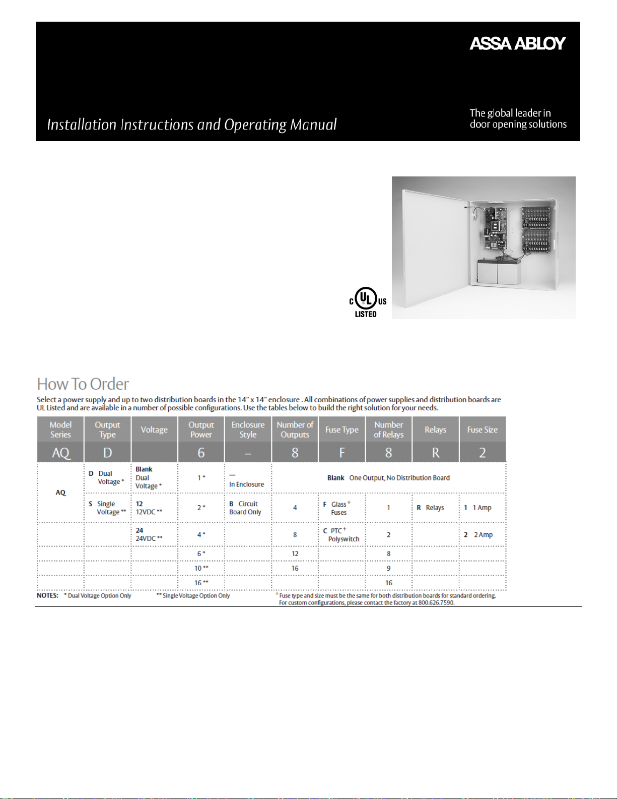
AQD6-16C2
AQD Series 12V/24V
Power Supply
Features
• Small – Light – Efficient – Clean Power
• Field Selectable AC Input: 120/240 VAC
• Rated Amperage available at 12 or 24VDC output, Selectable
• Tolerates brownout or overvoltage input ± 15% of nominal voltage
• High efficiency: up to 90% at 24V output, full load
• Battery Charger Maximum Charge Current: 0.7A
• Dedicated battery charging circuit for Wet, AGM, and Sealed Lead Acid Batteries
• Power Limited Output with Thermal Protection
• Reverse Battery Protection
• Battery Online, No Drop or Switchover with AC Power Fail
• UL Listed Access Control & Burglar Alarm Systems
• Set of Form “C” Relay Contacts Indicates AC Power Status
• Set of Form “C” Relay Contacts Indicates Low Battery
• Amber LED Indicates Power Normal
• DC Output is Class II Power Limited
• Lifetime Warranty
Description
The AQDX series are heavy-duty, self-contained, efficient, clean, offline switching power supplies, with linear-type performance, and are
jumper selectable between 12 VDC at 6A and 24 VDC at 6A. The AQDX series have a dedicated lead acid battery(s) charger that obtains
maximum battery life while providing 12 VDC or 24 VDC uninterruptible power for access control security systems. The field selectable AC
input on AQD2, 4, and 6 models allows these power supplies to be powered anywhere in the world. The AQDX series have exceptional
brownout capability with operation down to 85% of nominal voltage. The AQDX series have an extensive filtering system that provides
linear output performance, and they are electronically protected against battery reversal, shorting, or overloading. All variants are Power
limited output with thermal protection, AQD6 is power limited only when used with a distribution board. Each of these protective features
will self-restore.
NOTE: Before connecting load and battery(s), ensure the 12V/24V jumper is moved to the desired voltage.
CAUTION: Damage can occur when switching the DC output voltage. Proper voltage must be confirmed before connecting devices.
500-25010_2
1
Page 2

The AQDX series are UL Listed and have additional supervisory features:
120 / 240 VAC
(112W)
120 / 240 VAC
(216W)
UL recorded range for compatibility
on battery for 12 V configuration
UL recorded range for compatibility
on battery for 24 V configuration
battery)
Current overload short circuit
protection
Only when used with
PDB
Ambient operating temperature
range
Caution: To avoid spark, AC must be applied before connecting battery cable to battery
• Battery disconnect relay when battery(s) are depleted
• Set of Form “C” relay contacts that indicate AC power failure
• Set of Form “C” relay contacts that indicate low battery(s)
• DC Output is Class II power limited
• Green LED for local “AC” on indication
Depending on load, low battery trouble indicates 50–75% battery capacity remaining. Input wiring to the unit should be enclosed in conduit
secured firmly to the enclosure. The AQDX cannot be used to power a mercantile bell.
Specifications
Model AQD1 AQD2 AQD4 AQD6
AC Input
AC Input Terminals L,N,G – 3P Terminal Block with recessed hardware insulation accepts up to 12 AWG
AC Frequency 60 Hz 50 to 60 Hz
CAUTION: To prevent damage, the power supply board must be configured for the proper voltage before applying line voltage
Note: There is a removable link on the top of the power supply board. This link is cut and removed to convert to 240VAC. Once cut,
there is no conversion back to 120 VAC
DC Output Voltage Selection
CAUTION: To prevent damage, the DC load and battery(s) connections are removed before switching selector switch up or down.
DC Outputs 1 output, 2 Pin terminal block
Note: There is up to a 10 second delay for initial turn on
Output voltage nominal 12VDC / 24VDC
Output voltage typical 13.5 / 27.2 VDC 12.5 / 25.0 VDC
Output range with rated load 13.5 / 27.2 VDC 12.5 / 25.0 VDC
Output continuous current rating 1A 2A 4A 6A
Load regulation no load to max (no
120 VAC (39W)
The jumper is located near the center of the power supply board and is marked "12V 24V" The
jumper is moved to the appropriate pins to configure the output voltage
9.26 – 13.2 VDC 9.7 – 13.2 VDC
19.04 – 26.4 VDC 19.5 – 26.4 VDC
±0.2%
Yes Yes Yes Yes
120/240VAC (240W)
Thermal runaway protection Yes Yes Yes Yes
Power limited Output Yes Yes Yes
Note: Current overload and thermal shutdown will auto-restart without removing load
-4F to +122F (-20C to +50C)
Note: UL verified +32F to +120F (0C to +49C), not evaluated for outdoor use
DC LED Indicator Green
Battery Charging 2 Pin terminal block marked "-BAT+"
Fault reporting relay rating <32VDC, <240VAC, 3A, resistive load only
Note: The battery charger is precision set to float charge 12V or 24V sealed or wet lead acid batteries.
A 12-inch battery cable assembly is provided that plugs from module to battery: Red (+), Black (–) Neg.
Battery(s), any type of lead acid 12V / 24V, 4 AH–72AH
UL evaluated battery 7Ah 12Ah 18Ah 72Ah
Battery(s) recharge 100 mA max 200 mA Max 500 mA max 700 mA max
2
Page 3

Battery(s) average recharging
current
50 mA 75 mA 125 mA 250 mA
Battery(s) Reverse hookup
protection
Battery Max. Charge Voltage (no
load)
Note: Battery Cutoff Relay is normally energized for Fail-Safe operation.
alarm under full load conditions. Standby power has been evaluated in accordance with UL 1076 proprietary burglar alarm systems.
Note: Height Includes 7/16" standoffs, ½” standoffs minimum required
UL 294 6th Edition
Listed
Listed
Listed
Listed
Note 1: For UL294 Compliance when using 8 output PDB boards with fire trigger: Fire Alarm disconnect wire length must be less than
98.5 ft. (30m)
Note 2: For ULC-S318 compliance, the power supply battery fail line must be connected to and monitored by a control panel trouble
zone
Note 3: AQDX Series uses a standard power supply enclosure, not an attack proof enclosure. As such, they should not be used to power
a mercantile bell
Note 4: When using a battery that is not housed inside the power supply enclosure, the battery leads require protection from the
accommodate the standby batteries.
Note 5: When using AQDXB modules in another enclosure, minimum standard spacing between live electrical circuits shall be taken
into account
Note 6: Model AQD1B power supply requires a low battery disconnect module (model# BDM) manufactured by Life Safety Power. This
device is required to provide the required battery disconnection for ULC-S318.
Note 7: Power supplies shall be installed in accordance with the National Electrical Code, ANSI/NFPA 70, Canadian Electrical Code, or any
Battery(s) PTC self-resetting breaker 1A PTC 2A PTC 4A PTC 6A PTC
Model AQD1 AQD2 AQD4 AQD6
Yes, 500 mA PTC Yes, 1A PTC Yes, 2A PTC Yes, 4A PTC
AQD Supervised Added Features
AC Status Output Relay 3Pin Terminal block
AC Fail “C” contacts rating <32VDC, <240VAC, 3A, resistive load only
Note: AC fail relay is a three position AC fail terminal block marked “NO, C, NC” are shown in the Normal, energized, AC ON condition.
Battery LED Indicator Red
13.7 VDC /27.4 VDC
Battery Cutoff internal relay contacts <32VDC, <240VAC, 3A, resistive load only
Low Battery Cutoff 9V / 18 V for 12 V / 24V setting
Note: Sealed lead acid batteries have a typical life of 3 to 5 years. Make sure to mark batteries with the date they are installed.
Note: All power supplies are required to have a min of a 48 Hr recharge period to provide standby power of minimum 4 Hrs 15 Min of
Physical
Module Dimensions 5.75" x 3.25" x 2.3" 4.88" x 3.75" x 2.06" 6.06" x 3.88" x 2.44" 7.36" x 4.04" x 1.75"
Module in Enclosure Dimensions 14" x 14" x 4.83"
Enclosure Weight 6.9 lbs
UL Approvals
Line Security Level 1 1 1 1
Endurance Test Level 1 1 1 1
Attack test Level 1 1 1 1
Battery Standby Test Level 4 4 4 4
UL 603 Listed Listed Listed Listed
ULC-S318 Listed Listed Listed Listed
ULC-S533 Listed Listed Listed Listed
Compliance Notes:
enclosure via the use of conduit. The enclosure shall be UL Listed to the above categories and shall have sufficient space to
other applicable codes
Maintenance
The power supply and standby batteries should be tested at least once a year as follows:
1. CHECK LEDs for normal state: AC ON Green, Trouble Normal ON Green (Amber LED indicates trouble), DC ON Red.
3
Page 4

2. CHECK output voltage with normal load (assures proper voltage to float charge batteries): For 12V setting, voltage should read
AQDX
PCB
between 13.6 VDC and 13.8 VDC; and for 24V setting, voltage should read between 27.1 VDC and 27.6 VDC.
3. DISCONNECT AC input: AC LED should be off, and all other LED’s should remain normal.
4. CHECK DC output to be above 12.0 VDC for 12V setting and 24.0 VDC for 24V setting (checks standby batteries to be operational).
5. APPLY AC and VERIFY AC LED ON.
POWER
SUPPLY
AQDX in an enclosure with two PDBs in a 24V Configuration
Warranty
The AQDX is covered by the MagnaCare® lifetime replacement no fault warranty. No registration is required. Product will be replaced
forever, for any reason, including but not limited to installation error, vandalism, or act of God. Replacement product is shipped at
Securitron’s expense next day air, if needed.
For more information, visit www.assaabloyesh.com
500-25010_2
4
 Loading...