

AT&T Model SW-ATT-SMKT SMOKE ALARM
DESCRIPTION
The SW-ATT-SMKT is a photoelectric smoke alarm
with a built-in transmitter designed for use with the
ATT Digital Life Controller system. When smoke is
detected, the alarm sounds a loud local alarm. Twenty
seconds after the local alarm sounds, the built-in
transmitter sends a digitally coded wireless signal to
the Control Panel. The wireless signal will be repeated
every 20 seconds as long as smoke is still present. In
addition to the photoelectric detector, the unit
contains an integrated fixed 135° temperature and
rate-of-rise heat sensor that will send an alarm signal
based on temperature detected.
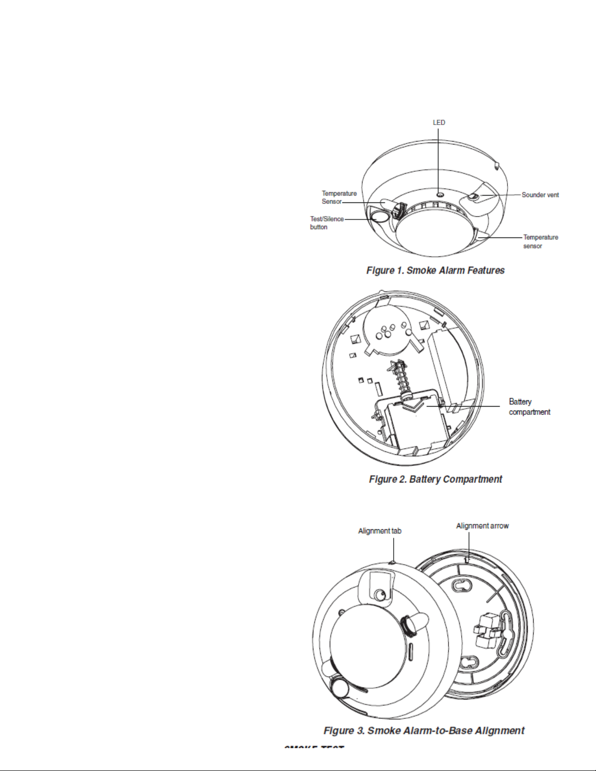
INSTALLATION
1. Slide the battery compartment cover away from the
unit to unsnap it and lift it off. See Figure 2.
2. Observing proper polarity, insert the two 3V lithium
batteries supplied into the alarm battery
compartment and replace the battery cover.
3. Remove the red plastic dust cover from the unit.
4. Refer to Page 3 for selecting a proper location for
the smoke alarm.
5. Using the two screws and anchors provided, mount
the base.
6. Attach the unit to the base as follows:
• Line up the raised alignment tab on the lip of the
unit with the alignment arrow on the base. See Figure
3.
• Insert the unit into the base and turn clockwise
approximately 15 degrees. It should snap firmly into
place.
IMPORTANT: The unit cannot be attached to the
base if no batteries are installed.
DISCOVER AND REGISTER THE SMOKE
DETECTOR
Reference Section Error! Reference
source not found., “Enter Discovery
Mode for Device Detection” for
instructions on entering the discovery
mode.
Click on the Start Discovery button to
enter the discovery mode on the DLC.
Enroll the Smoke Detector by pressing
and holding the test button for a
minimum of two (2) seconds.
Verify that the device appears on the
“Device Setup” page along with its
unique device ID.

SENSITIVITY TEST
1. Press and hold the TEST/SILENCE button for 4 seconds. Once the test starts, the smoke alarm LED flashes 1 to 9
times.
2. Count the number of LED flashes and use the following table to determine if any action is necessary.
FLASHES INDICATION ACTION
0-1 Unserviceable hardware fault. Reset and rerun sensitivity test. If
the error persists, replace the unit.
2-3 Unit is becoming insensitive. Clean and reset the unit. Rerun sensitivity test. If the error persists, replace the
unit.
4-7 Unit is within normal sensitivity range No action required
8-9 Unit is becoming too sensitive. Verify that the optical chamber is
snapped down securely. Clean the unit and replace the optical chamber.
After the LED flashes, if the sensitivity is within limits and all other tests pass,
the unit goes into alarm and resets after 7 seconds. If the sensitivity is not
within limits, or an unserviceable hardware fault has been detected, the unit
LED extinguishes until the unit is serviced.
LED FUNCTIONS
Flashing — Flashes every 9 seconds to indicate normal operation.
On — Detects smoke
Off — Trouble or maintenance is required.
Case Tamper Detection
Removing the cover of the SW-ATT-SMKT will cause the integral transmitter to send a case tamper report to the Digital Life
Controller. This tamper condition will remain on the system until the case cover is installed and the integral transmitter sends a
tamper restore to the Digital Life Controller.
WHEN TO REPLACE THE BATTERIES
When the batteries are low; the integral transmitter will send a low battery report to the Digital Life Controller,
extinguish its LED and chirps every 45 seconds until the batteries are replaced. The low battery trouble chirps can be
silenced for 24 hours by pressing the TEST/SILENCE button. Battery life is a minimum of one year, and varies depending
on how often the unit is tested.
REPLACING THE BATTERIES
Use only 3V lithium batteries listed on the battery compartment cover.
1. Remove the unit from the mounting base, grasp the unit and turn it
Counter clockwise approximately 15 degrees.
2. Slide the battery compartment cover away from the smoke alarm to
unsnap it and lift it off. See Figure 2.
3. Remove the batteries and dispose of them properly.
4. Observing correct polarity, insert two new CR123A 3V lithium batteries into the battery compartment
and replace the cover.
5. Reattach the unit to the mounting base. See Installation, Step 6.
6. Test the system.
CLEANING
Clean the cover with a dry or damp (water) cloth as needed to keep it free from dust and dirt.
When necessary, clean the interior and replace the optical chamber (part number ??????) as follows:
1. To remove the unit from the mounting base, grasp the unit and turn it Counter-clockwise approximately 15
degrees.
2. Remove the batteries.
3. Slide a flat-blade screwdriver in the slot on the alarm cap and gently push the handle down to pry the alarm cap
up and off. See Figure 4.
4. Squeeze the optical chamber where indicated and pull it up and away from the optical base and discard. See
Figure 5.

5. Blow out or use a soft-bristled brush to remove all dust and dirt from the optical base.
6. Line the new smoke chamber up with the optical base by lining up the arrows on the optical chamber to the
latches on the optical base. Ensure that the LED cavity in the optical chamber is above the LED and snap the
optical chamber down into place.
7. To replace the alarm cap as follows:
• Line the alarm cap up with the unit.
• Insert the alarm cap into the unit and turn clockwise approximately 15 degrees. It should snap firmly into
place.
8. Observing proper polarity, replace the batteries and the battery compartment cover.
9. Reattach the unit to its mounting base. See Installation, Step 6.
10. Test the unit sensitivity.
MAINTENANCE
The units are designed for easy field service and maintenance. When installed and used properly, they require minimal
maintenance.
The unit should be tested weekly.
When a unit requires maintenance, it extinguishes its LED and stops sending supervisory signals to the alarm Control
Panel.
If the Control Panel indicates supervisory trouble for the smoke alarm, perform the sensitivity test and follow the
recommended actions.
SPECIFICATIONS
Voltage 3VDC
Typical average standby current 35μA
Typical test current 2mA
Typical alarm current 70mA
Battery type 3V lithium, Duracell® 123A, Panasonic®
CR123A, Sanyo® 123A
Low battery threshold 2.70V causes low battery signal
Sounder 85dBa at 10’ temporal pattern
Low battery beep rate 1 every 45 sec.
Sensitivity 2.2% ± 1.3% / ft.
Operating temperature 40°-100°F (4.4°-37.8°C)
Operating humidity range 0-95% non-condensing
Color White
Alarm dimensions 5.6” x 2.4” (14.2 cm x 6.1cm)
Base dimensions 5.4” x 0.46” (13.7 cm x 1.17cm)
Drift compensation adjustment 0.5% / ft. max.
Heat detector specifications
Rate-of-rise 15°F/min>105°F
(8.3°C/min>40.6°C
Fixed 135°F ± 5°F (57.2°C ± 2.8°C)
Listings, UL217, CSFM
FCC Compliance
This device complies with FCC Rules and Regulations as Part 15 devices as well as Industry Canada Rules and Regulations.
Operation is subject to the following two conditions:
1. This device may not cause harmful interference.
2. This device must accept any interference received, including interference that may cause undesired operation. Changes or
modifications not expressly approved by the party responsible for compliance could void the user’s authority to operate
the equipment.
Conformité Réglementaire
Ce dispositif est conforme à la réglementation de la IC et (Partie 15) de la FCC. Son fonctionnement est soumis à deux conditions : (1) ce
dispositif ne doit pas causer d’interférences nuisibles, et (2) ce dispositif doit accepter toute interférence reçue, y compris les interférences
pouvant entraîner des conditions de fonctionnement indésirables.

IMPORTANT INFORMATION ABOUT RADIO DEVICES
1. AT&T radio controls provide a reliable communications link and fill an important need in
portable wireless signaling. However, there are some limitations which must be observed.
2. For US installations only: the radios are required to comply with FCC rules and regulations
including FCC part 15 devices. As such, they have limited transmitter power and therefore
limited range.
3. A receiver cannot respond to more than one transmitted signal at a time and may be blocked by
radio signals that occur on or near their operating frequencies regardless of code settings.
4. Changes or modifications to the device may void FCC compliance
5. Infrequently used radio links should be tested regularly to protect against undetected
interference or fault.
6. RF signals can be affected by metal objects including metal doors or large mirrors. Care should
be taken to avoid these objects during installation as they can interfere with proper operation.
7.
WARNING: The polarity of the battery must be observed. Improper handling of lithium batteries
may result in heat generation, explosion or fire which may lead to personal injuries. Replace
only with the same or equivalent type of battery as recommended by the manufacturer.
Batteries should not be recharged, disassembled or disposed of in fire. Disposal of used batteries
must be made in accordance with the waste recovery and recycling regulations in your area.
Notice to users in California—This Percolate warning applies only to Manganese Dioxide Lithium
cells sold or distributed only in California, USA. Percolate Material special handling may apply.
See www.dtsc.ca.gov.hazardouswaste/perchlorate.
 Loading...