

C-Stat 11-M | C-Stat 17-M
Installation Instructions
Mains Operated Programmable Room Thermostat
Programmable room thermostats are widely recognised as one
of the best ways in which to control central heating. C-Stat
programmable room thermostats have a large display and
intuitive user interface, making them easy to set up and use. CStat uses a sophisticated load compensation (LC) algorithm for
accurate temperature control and energy efficiency. Being
mains powered these models won't need the batteries changing
every two years.
Installation and connection should only be carried out by a
suitable qualified person and in accordance with the edition of
the IEE wiring regulation.
Warning: Isolate mains supply before commencing installation.
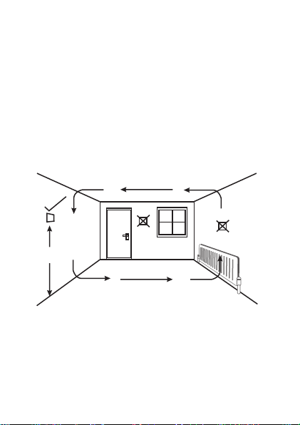
Positioning the C-Stat programmable room
thermostat
The C-Stat should be mounted on an internal wall
approximately 1.5 metres from floor level and should be
in a position away from draughts, direct heat and
sunlight. Ensure that there will be enough space to allow
access to the two retaining screws located at the base of
the wall plate.
1.5m
2
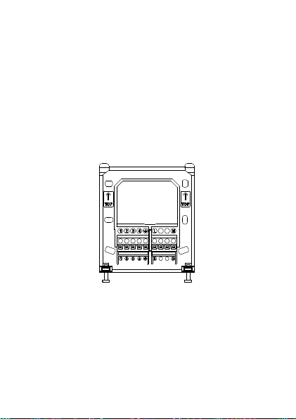
Fitting the wall plate
To remove the wall plate from the C-Stat undo the two retaining
screws located on the underside, the wall plate should now be
easily removed. Once the wall plate has been removed from the
packaging please ensure the C-Stat is resealed to prevent
damage from dust, debris etc.
The wall plate should be fitted in a position which allows a total
clearance of at least 50mm around the C-Stat programmable
thermostat.
Direct Wall Mounting
Offer the plate to the wall in the position the C-Stat is to be
mounted and mark the fixing positions through the slots in the
wall plate. Drill and plug the wall, then secure the plate in
position. The slots in the wall plate with compensate for any
misalignment of the fixings.
3
Wiring Box Mounting
The C-Stat wall plate may be fitted directly on to a single gang
steel flush wiring box complying with BS4662, using two M3.5
screws. The C-stat is suitable for mounting on a flat surface only;
it must not be positioned on an unearthed metal surface.
Electrical Connections
All necessary electrical connections should now be made. Flush
wiring can enter from the rear through the aperture in the wall
plate.
A Pattress is supplied to allow mains surface wiring to enter the
unit.
The mains supply terminals are intended to be connected to the
supply by means of fixed wiring.
The C-Stat is mains powered and requires a 3 Amp fused spur.
The recommended cable size is 1.0mm².
The C-Stat is double insulated and does not require an earth
connection, an earth connection block is provided on the
backplate for terminating any cable earth conductors. Earth
continuity must be maintained and all bare earth conductors
must be sleeved. Ensure that no conductors are left protruding
outside the central space enclosed by the backplate.
4

Internal wiring diagram
These diagrams are schematic and should be used for guidance
only. Please ensure that all wiring complies with current IEE
regulations
CALL
1 2 3 4 L N
230V
MAINS
CALL FOR
HEAT
Ÿ The C-Stat have voltage free contacts
Ÿ For mains voltage switching applications, link terminal L-1
Ÿ For low voltage switching applications, apply low voltage to
terminal 1 with no links.
SUPPLY
5

C-Stat
Remove link
if Fitted
1 3N2 4
N
L
E
L
N
L
E
L
N
L
PUMP
N
&
BOILER
L
1 3N2 4
L
Mains
N
Supply
E
E
E
L
N
COMBINATION BOILDER
Programmer
HOT
WATER
OFFONOFF
ON
C CN
CYL
STAT
CALL
SAT
TERMINALS
1 2
N
COOLING LOAD
CENTRAL
HEATING
ROOM
STAT
ROOM
STAT
CALL
SAT
3
4
L
MAINS
SUPPLY
C-Stat controlling typical combination boiler installation. For precise termination
connection information please refer to the boiler manufactures instructions
E
Mains
L
Supply
N
C-Stat wired to control a cooling load. When necessary the C-Stat should be used in
conjunction with a contactor.
N L
N
MAINS
L
SUPPLY
E
C-Stat controlling a secondary heating zone on a fully pumped system with existing
programmer and two spring return valves with auxiliary switches.
6
Mains
Supply

Programmer
HOT
CENTRAL
WATER
HEATING
OFF
ON
N L
N
MAINS
L
SUPPLY
E
W
BL
0
GR
C-Stat replacing a conventional room thermostat on a fully pumped system with an
existing programmer and 3 port mid-position valve.
C
CALL
OFF
ON
C-Stat
CYL
1
STAT
3
4
CALLSAT
SAT
L
N
PUMP
&
BOILER
230V
L
MAINS
SUPPLY
N
Programmer
HOT
CENTRAL
WATER
HEATING
OFFONOFF
ON
N L
N
MAINS
L
SUPPLY
E
C-Stat replacing a conventional room thermostat on a fully pumped system with an
existing programmer and two spring return valves with auxiliary switches
N
PUMP
BOILER
C
CYL
STAT
CALL
L
&
C-Stat
1
4
3
CALLSAT
SAT
230V
L
MAINS
SUPPLY
N
7

All wiring diagrams are schematic and should be used for guidance only.
INSTALLATION AND CONNECTION OF THE C-STAT MUST BE CARRIED OUT BY A
SUITABLY QUALIFIED PERSON.
WARNING: ISOLATE MAINS SUPPLY BEFORE COMMENCING INSTALLATION
LC Temperature control software
Thermostats using LC (Load Compensation) control algorithms
will reduce the temperature swing that normally occurs when
using traditional bellows or thermally operated thermostats. As a
consequence, a LC regulating thermostat will maintain the
comfort level far more efficiently than any traditional thermostat.
When used with a condensing boiler, the LC thermostat will help
to save energy as the control algorithm allows the boiler to
operate in condensing mode more consistently compared to
older types of thermostat.
Ÿ For Gas boilers ser the LC setting to 6 cycles per hour (default
setting)
Ÿ For Oil boilers set the LC setting to 3 cycles per hour
Ÿ For Electric heating set the LC setting to 12 cycles per hour
To adjust this setting go to the SET UP MENU and select LC
CYCLES
8

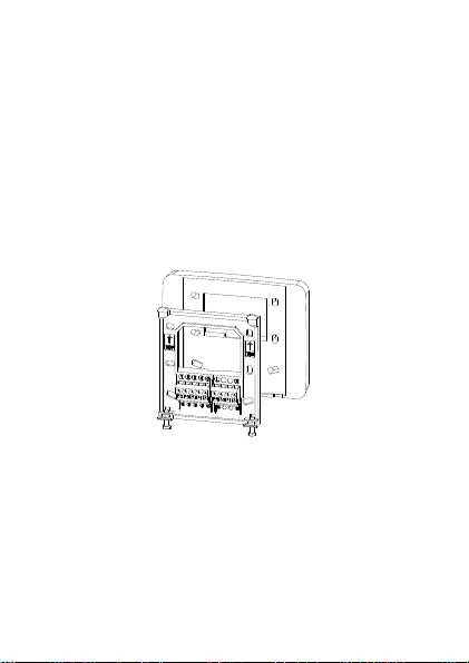
Fitting the C-Stat to the wall plate
Complete the installation by swinging the C-Stat into position by
engaging the lugs at the top of the wall plate before pushing it
firmly home into its plug-in terminal block.
Tighten the 2 captive screws on the underside of the unit.
Now ensure that the heating system is responding to the On/Off
commands from the C-Stat. Explain its operation to the
householder and hand over the users operating instructions to
the user.
9

Installer Settings
There are a number of 'Installer Settings' that should be set on
installation.
These can be found under the 'SET UP MENU' on page 15 of the
user instructions.
Clock Format AM/PM or 24 Hour clock display - Default
Daylight saving On or Off - Default setting ON for UK Market
Standby temperature Frost protection setting – Default setting 5°C
Upper and Lower Default settings 30°C and 5°C
Temperature limits
LC Cycles This setting will change according to the
For Gas boiler this setting should be 6
For Oil boilers this setting should be 3
For Electric panel heaters this should be 12
Optimum Start On or Off – Default setting Off
The LC Cycles setting and Optimum Start settings should be carefully
set on installation as this will affect system performance.
10
setting AM/P
type of boiler being used - Default setting 6
cycles per hour
cycles per hour
cycles per hour

Resetting the thermostat
Electronic equipment can in some circumstances be affected by
electrical interference.
If the display becomes frozen or scrambled simply press both
the BACK and ENTER button simultaneously.
Using this procedure will restore the C-Stat to the original factory
settings, the Time and Date will remain correct.
BACK
ENTER
11

Specification – C-Stat 11-M | C-Stat 17-M
NP0 08 48 73 00 0
Purpose of Control Thermostat
Power Supply 230V 50Hz
Contact type Micro-disconnection
Wiring configuration Voltage free c/o contacts (SPDT)
Contact voltage rating 230V ac 50Hz (30V dc)
Contact current rating 8A (1A inductive)
Temperature differential 0.5°C
Temperature accuracy +/- 0.5°C to 21°C
Impulse rating Category II 2500 V
Standards BS EN 60730-2-9, EN 60730-2-9
Dimensions (WxHxD) 120mm x 100mm x 26.5mm
Weight 0.3kg (approx)
Enclosure Flame retardant thermoplastic
Ingress protection IP30
Pollution degree Degree 2
Insulation class Class II (Double Insulated)
Software class Class A
Control type Type 2B
Temperature range 0°C to 40°C
Electronic Control
Ball Pressure Temperature 75 °C
Construction of Control Electronic control
Secure Meters (UK) Ltd
Secure House, Lulworth Close,
Chandler's Ford,
Eastleigh, SO53 3TL, UK
t: +44 1962 840048 f: +44 1962 841046
www.Securemeters.com
Part Number P84873 Issue 6
 Loading...