

Page 1
CCHHAANNNNEELLPPLLUUSS HH4477XXLL SSEERRIIEESS 22
IINNSSTTAALLLLAATTIIOONN IINNSSTTRRUUCCTTIIOONNSS
INSTALLATION AND CONNECTION SHOULD ONLY BE CARRIED OUT BY A SUITABLY QUALIFIED PERSON
AND IN ACCORDANCE WITH THE CURRENT EDITION OF THE IEE WIRING REGULATIONS.
WWAARRNNIINNGG :: IISSOOLLAATTEE MMAAIINNSS SSUUPPPPLLYY BBEEFFOORREE CCOOMMMMEENNCCIINNGG IINNSSTTAALLLLAATTIIOONN
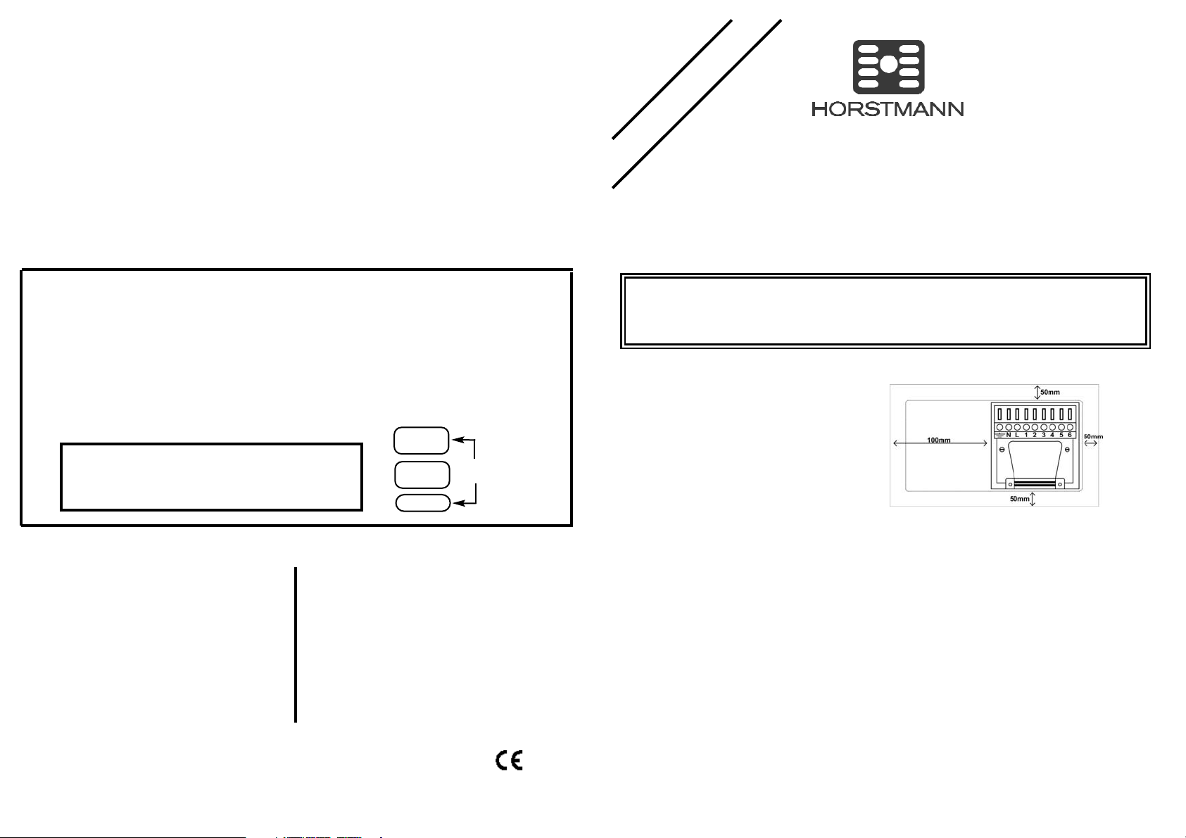
FFIITTTTIINNGG TTHHEE BBAACCKKPPLLAATTEE
Once the Backplate has been removed from the
packaging please ensure the programmer is
re-sealed to prevent damage from dust, debris
etc.
The Backplate should be fitted with the wiring
terminals located at the top and in a position
which allows the relevant clearances around
the programmer. (See diagram)
DDIIRREECCTT WWAALLLL MMOOUUNNTTIINNGG
Offer the plate to the wall in the position where the programmer is to be mounted, remembering that
the Backplate fits to the right hand end of the programmer.
Mark the fixing positions through the slots in the Backplate (Fixing centres 60.3mm), drill and plug the
wall, then secure the plate in position. The slots in the Backplate will compensate for any
misalignment of the fixings.
WWIIRRIINNGG BBOOXX MMOOUUNNTTIINNGG
The Backplate may be fitted directly on to a single gang steel flush wiring box complying with BS4662,
using two M3.5 screws.
ChannelPlus series 2 programmers are suitable for mounting on a flat surface only, they must not be
positioned on a surface mounted wall box or on unearthed metal surfaces.
EELLEECCTTRRIICCAALL CCOONNNNEECCTTIIOONNSS
All necessary electrical connections should now be made. Flush wiring can enter from the rear through
the aperture in the Backplate. Surface wiring can only enter from beneath the programmer and must be
securely clamped.
The mains supply terminals are intended to be connected to the supply by means of fixed wiring.
The recommended cable sizes are 1.0mm
2
or 1.5mm2.
Page 1Page 4
LEAFLET No P82733
ISSUE 1
SSPPEECCIIFFIICCAATTIIOONN HH4477XXLL SSEERRIIEESS 22
CCoonnttaacctt ttyyppee::
Micro dis-connection(Voltage free)
CCoonnttaacctt rraattiinngg::
3(1)Amps 230-240V AC
PPoowweerr ssuuppppllyy::
230V AC 50Hz
OOppeerraattiinngg TTeemmppeerraattuurree rraannggee::
0oC to 40oC
DDoouubbllee iinnssuullaatteedd..
DDiirrtt pprrootteeccttiioonn::
Normal situations.
EEnncclloossuurree pprrootteeccttiioonn::
IP30
PPuurrppoossee ooff ccoonnttrrooll::
Electronic time switch
IInnddeeppeennddeennttllyy mmoouunntteedd ccoonnttrrooll ffoorr ssuurrffaaccee mmoouunnttiinngg..
OOppeerraattiinngg ttiimmee lliimmiittaattiioonn::
Continuous
BBaatttteerryy TTyyppee::
Lithium
CCaassee mmaatteerriiaall::
Thermoplastic, flame retardant
DDiimmeennssiioonnss::
163mm x 101mm x 37mm
DDiissppllaayy::
Fully graphical LCD, back-lit
CClloocckk::
24hour /12 hour AM/PM
DDiissppllaayy ttiimmee aaddjjuussttmmeenntt::
1 Minute steps
SSwwiittcchheedd ttiimmee aaddjjuussttmmeenntt::
10 Minute steps
PPrrooggrraammmmee sseelleeccttiioonn::
Auto, On all day, On constant, Off, Holiday
OOppeerraattiinngg ppeerriiooddss ppeerr ddaayy::
Three for Heating 1, Heating 2 and
Water (separate daily programme for each Channel)
OOvveerrrriiddee::
Boost, 1 or 2 Hours
Extension to ON period, 1 Hour or 2 Hour
Instant Advance
BBaacckkppllaattee::
9 Pin terminal connection
Horstmann Controls Limited
Bristol
BS4 1UP
t:0117 9788 773 - f:0117 9788 701
Email: sales@horstmann.co.uk
Website: www.horstmann.co.uk
GGEENNEERRAALL IINNFFOORRMMAATTIIOONN
BBAATTTTEERRYY
The programmer is fitted with a non-rechargeable, non-serviceable long life battery, which will
maintain the programmed time settings with the mains supply disconnected.
THIS RESERVE SHOULD BE SUFFICIENT TO COVER POWER INTERRUPTIONS DURING THE LIFE OF THE UNIT.
During power interruptions the display will be blank.
SSEERRVVIICCEE AANNDD RREEPPAAIIRR
This programmer is NOT user serviceable. Please do not dismantle the unit. In the event of a fault
developing please refer to the RESETTING THE PROGRAMMER section below. If this fails to resolve the
problem please contact a local heating engineer or a qualified electrician.
HHoorrssttmmaannnn CChhaannnneellPPlluuss HH4477XXLL SSeerriieess 22 -- FFoouurr CChhaannnneell CCeennttrraall HHeeaattiinngg aanndd HHoott WWaatteerr
PPrrooggrraammmmeerr..
The H47XL programmer offers the equivalent of four independent seven day timers in
one modern, good looking enclosure.
Each of the four channels offers up to three programmed operating periods per day for
each of the seven days of the week, with a boost and advance available on each.
The fully graphical back-lit display combined with menu driven programming is
designed to simplify the day-to-day operation of the H47XL
Lower the front flap of the unit. On the far right (forth)
Channel press the ADVANCE(Enter) and SELECT(Blue)
buttons together then release the buttons and the
programmer will return to the preset factory settings.
RREESSEETT PPRROOCCEEDDUURREE
PPLLEEAASSEE NNOOTTEE;;
Using this procedure will restore the ChannelPlus to the original factory programme
settings, the time setting will remain correct.
Electronic equipment can in some circumstances be affected by electrical interference. If the display
becomes frozen or scrambled; or if you wish to revert back to the default settings please use the
following procedure.
RREESSEETTTTIINNGG TTHHEE CCHHAANNNNEELLPPLLUUSS HH4477XXLL SSEERRIIEESS 22
ADVANCE
SELECT
BOOST
RESET
Page 2
Page 2
ChannelPlus programmers are double insulated and do not require an Earth connection but an Earth
terminal is provided on the Backplate for terminating any cable Earth conductors.
Earth continuity must be maintained and all bare Earth conductors must be sleeved. Ensure that no
conductors are left protruding outside the central space enclosed by the Backplate. When used to
EELLEECCTTRRIICCAALL CCOONNNNEECCTTIIOONNSS
CCOOMMMMIISSSSIIOONNIINNGG TTHHEE PPRROOGGRRAAMMMMEERR
Ensure all dust and debris has been cleared away from the work area before removing the programmer
from its packaging.
All ChannelPlus XL controls are fitted with a battery reserve which maintains programmed times in the
event of a mains power failure.
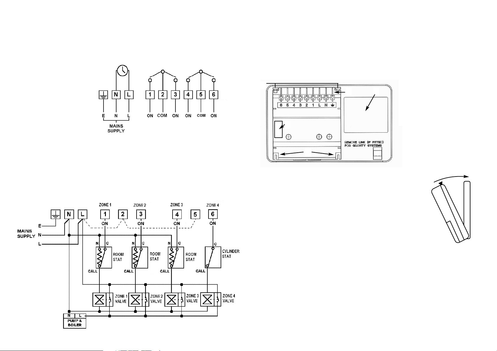
RREEAARR VVIIEEWW OOFF CCHHAANNNNEELLPPLLUUSS XXLL PPRROOGGRRAAMMMMEERR
NNEEWW IINNSSTTAALLLLAATTIIOONNSS
FFIITTTTIINNGG TTHHEE PPRROOGGRRAAMMMMEERR
If surface wiring has been used, remove the knockout/insert from the bottom
of the programmer to accommodate it. Loosen the two ‘captive’ retaining
screws on the top of the unit. Now fit the programmer to the Backplate, line
the lugs on the programmer with the flanges on the Backplate.
Swing the top of the programmer into position ensuring that the
connection blades on the back of the unit locate into the terminal slots in the
backplate.
Tighten the two ‘captive’ retaining screws to fix the unit securely, then switch
on the mains supply.
END VIEW OF CHANNELPLUS PROGRAMMER
1 - RETAINING SCREWS
2 - CONNECTOR BLADES
3 - PRODUCTION DATE LABEL
4 - POSITIONING LUGS
5 - RATINGS LABEL
ChannelPlus H47XL Series
2 shown controlling 4 x
two port spring return
zone valves via Room
Stat and Cylinder Stat
giving independent
control of Hot water and
three zones of Heating.
NNOOTTEE::
If the ChannelPlus H47XL Series 2 is being installed on an existing system additional equipment
such as extra zone valves will have to be fitted in order to achieve full four channel control.
INTERNAL WIRING DIAGRAM H47XL Series 2
PPlleeaassee eennssuurree tthhaatt aallll iinnssttaallllaattiioonnss ccoommppllyy wwiitthh tthhee ccuurrrreenntt IIEEEE rreegguullaattiioonnss..
For reasons of space and clarity the diagram has been simplified, for instance some Earth connections
have been omitted. Other control components shown in the diagram i.e. Valves, RoomStats etc. are general representations only. However the wiring detail can be applied to the corresponding models of most
manufacturers e.g. Horstmann, Honeywell, Danfoss Randall etc.
CCyylliinnddeerr aanndd RRoooomm TThheerrmmoossttaatt KKeeyy::
CC == CCoommmmoonn CCAALLLL == CCaallll ffoorr hheeaatt oorr bbrreeaakk oonn rriissee SSAATT == SSaattiissffiieedd oonn rriissee NN == NNeeuuttrraall
1
2
3
4
5
IINNIITTIIAALL SSEETT--UUPP
Once the mains power has been switched on the ChannelPlus H47XL Series 2’s display will illuminate.
The programmer has a number of pre-programmed functions to assist the initial set-up, which are
detailed below;
TTIIMMEE AANNDD DDAATTEE --
The programmer has been pre-set with the current time and date during manufacture.
No alteration should be required to the time and date, however if any modification is required please
refer to the ‘Adjusting Time and Date’ section of the user guide.
PPRROOGGRRAAMMMMEE TTIIMMEESS --
The programmer has been pre-set with default heating and hot water times, these
can be altered to meet the user requirements, please refer to the ‘Setting the Programme Times’
section of the user guide.
PPLLEEAASSEE EENNSSUURREE TTHHAATT TTHHEE UUSSEERR GGUUIIDDEE IISS HHAANNDDEEDD OOVVEERR TTOO TTHHEE EENNDD UUSSEERR..
Page 3
control MAINS VOLTAGE SYSTEMS
Terminals L,2 and 5 should be
electrically linked by means of a
suitable piece of sleeved
conductor. When used to control
EXTRA LOW VOLTAGE SYSTEMS
these links MUST NOT be fitted.
An example circuit diagram is
shown below. This diagram is
schematic and should be used as
a guide only.
PPlleeaassee eennssuurree tthhaatt
aallll iinnssttaallllaattiioonnss ccoommppllyy wwiitthh tthhee
ccuurrrreenntt IIEEEE rreegguullaattiioonnss..
 Loading...