

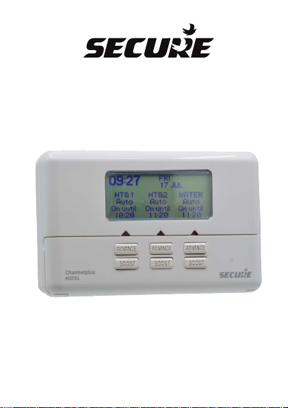
ChannelPlus H37XL Series 2
Installation Instructions
Three Channel Programmer
1
ChannelPlus H37XL Series 2 - Three Channel Programmer -
Each channel offers up to three programmed operating periods
per day, seven days a week, with three independent Boost and
Advance control on Fully Pumped Systems. This model offers a
fully graphical, back-lit display combined with simple menu
driven programming.
It is also a suitable direct replacement for existing ChannelPlus
H37XL programmers, utilising existing wiring and backplate
connections.
INSTALLATION AND CONNECTION SHOULD ONLY BE CARRIED
OUT BY A SUITABLY QUALIFIED PERSON AND IN ACCORDANCE
WITH THE CURRENT EDITION OF THE IET WIRING REGULATIONS.
WARNING: ISOLATE MAINS SUPPLY BEFORE COMMENCING INSTALLATION
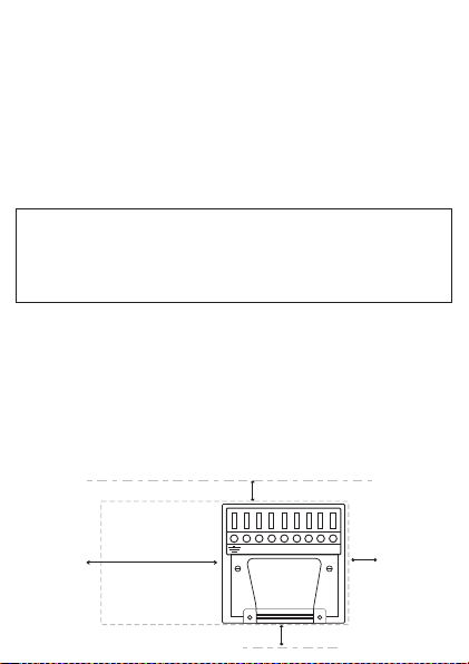
Fitting the Backplate
Once the Backplate has been removed from the packaging,
please ensure the programmer is re-sealed to prevent damage
from dust, debris etc. The Backplate should be fitted with the
wiring terminals located at the top and in a position which allows
the relevant clearances around the programmer.
(See diagram)
50 mm
100 mm
N L 1 2 3 4 5 6
50 mm
50 mm
2

Direct Wall Mounting
Offer the plate to the wall in the position where the programmer is
to be mounted, remembering that the Backplate fits to the right
hand end of the programmer.
Mark the fixing positions through the slots in the Backplate
(Fixing centres 60.3mm), drill and plug the wall, then secure the
plate in position. The slots in the Backplate will compensate for
any misalignment of the fixings.
Wiring Box Mounting
The Backplate may be fitted directly on to a single gang steel
flush wiring box complying with BS4662, using two M3.5 screws.
ChannelPlus series 2 programmers are suitable for mounting on
a flat surface only, they must not be positioned on a surface
mounted wall box or on unearthed metal surfaces.
Electrical Connections
All necessary electrical connections should now be made. Flush
wiring can enter from the rear through the aperture in the
Backplate. Surface wiring can only enter from beneath the
programmer and must be securely clamped.
The mains supply terminals are intended to be connected to the
supply by means of fixed wiring. The recommended cable sizes
are 1.0mm or 1.5mm
2 2
3
Electrical Connections
ChannelPlus programmers are double insulated and do
not require an Earth connection but an Earth terminal is
provided on the Backplate for terminating any cable
Earth conductors.
Earth continuity must be maintained and all bare Earth
conductors must be sleeved. Ensure that no conductors
are left protruding outside the central space enclosed by
the Backplate.
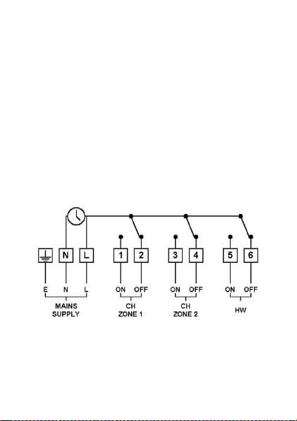
INTERNAL WIRING DIAGRAM H37XL SERIES 2
4

New Installations
An Example circuit diagram is shown below. This diagram is
schematic and should be used as a guide only.
Please ensure that all installations comply with the current
IET regulations.
For reasons of space and clarity the diagram has been simplified,
for instance some Earth connections have been omitted. Other
control components shown in the diagrams i.e. Valves,
RoomStats etc. are general representations only. However the
wiring detail can be applied to the corresponding models of most
manufacturers.
Cylinder and Room Thermostat Key:
C = Common CALL = Call for heat or break on rise SAT =
Satisfied on rise N = Neutral
ChannelPlus H37XL
Series 2 Controlling
3 x two port spring
return zone valves
via Ro omStat and
CylinderStat giving
independent control
of Hot water and two
zones of Heating.
NOTE: If the ChannelPlus H37XL Series 2 is being installed on an existing
system, additional equipment such as an extra zone valve may have to be
fitted in order to achieve full three channel control.
5

Commissioning the Programmer
Ensure all dust and debris has been cleared away from
the work area before removing the programmer from its
packaging.
All ChannelPlus XL controls are fitted with battery
reserve which maintains programmed times in the event
of a mains power failure.
Rear View of Channelplus XL Programmer
1
6 5 4 3 2 1 L N
3
4
5
2
REMOVE LINK (IF FITTED)
FOR GRAVITY SYSTEMS
1 - RETAINING SCREWS
2 - CONNECTOR BLADES
3 - PRODUCTION DATE LABEL
4 - POSITIONING LUGS
5 - RATINGS LABEL
6

Fitting the Programmer
If surface wiring has been
used remove the knockout
/ insert from the bottom of
the programmer to
accommodate it. Loosen
the two ‘captive’ retaining
screws on the top of the
unit. Now fit the
programmer to the
Backplate, line the lugs on
the programmer with the
flanges on the Backplate.
Swing t he to p of the
END VIEW OF
CHANNELPLUS
PROGRAMMER
programmer into position
ensuring that the connection blades on the back of the
unit locate into the terminal slots in the backplate.
Tighten the two ‘captive’ retaining screws to fix the unit
securely, then switch on the mains supply.
7

Initial Setup
Once the mains power has been switched on the
ChannelPlus H37XL display will illuminate. The
programmer has a number of pre-programmed functions
to assist the installation, which are detailed below;
Time and Date - The programmer has been pre-set with
the current time and date during manufacture. No
alteration should be required to the time and date, however
if any modification is required please refer to the ‘Adjusting
Time and Date’ section of the user guide.
Programme Times - The programmer has been pre-set
with default heating and hot water times, these can be
altered to meet the user requirements, please refer to the
‘Setting the Programme Times’ section of the user guide.
PLEASE ENSURE THAT THE USER GUIDE IS HANDED
OVER TO THE END USER.
General Information
BATTERY
The programmer is fitted with a non-rechargeable, nonserviceable long life battery, which will maintain the
programmed time settings with the mains supply
disconnected.
THIS RESERVE SHOULD BE SUFFICIENT TO COVER
POWER INTERRUPTIONS DURING THE LIFE OF THE
UNIT. During power interruptions the display with be blank.
8

SERVICE AND REPAIR
This programmer is NOT serviceable. Please do not
dismantle the unit. In the unlikely event of a fault
developing please refer to the RESETTING THE
PROGRAMMER section of this user guide located
below. If this fails to resolve the problem please contact a
local heating engineer or a qualified electrician.
Resetting the Channelplus H37XL Series 2
Electronic equipment can in some circumstances be
affected by electrical interference. If the display becomes
frozen or scrambled; or if you wish to revert back to the
default settings please use the following procedure.
Reset Procedure
PLEASE NOTE; Using this procedure will restore the
ChannelPlus to the original factory programme settings.
The time setting will remain correct.
ADVANCE
BOOST
SELECT
Lower the front flap of the unit. On the far right (third) Channel,
press the ADVANCE (Enter) and SELECT (Blue) buttons
together then release the buttons and the programmer will
return to the preset factory settings.
RESET
9

Specification ChannelPlus H37XL
Electrical
Purpose of Control Electronic Central Heating
Programmer (3 Channel)
Supply 230V AC 50Hz only
Contact Rating 3(1)Amps 230 V AC
Contact Type Micro-disconnection
Insulation Class II
Control Action 1B, R
Operating Time Limitation Intermittent
Software Class Class A
Battery Type Lithium
Battery Life 10 months continuous
operation (minimum)
Display Full graphical LCD, Backlit
Clock 24 Hour / 12 Hour AM/PM
Display Time Adjustment 1 minute intervals
Switch time Adjustment 10 minute steps
Programme Selection Auto, On, All Day, On
Constant, Off, Holiday
Operating Periods 3 for each channel
independently
Override Boost 1 or 2 Hours (If
pressed during ON period,
will extend ON period)
Instant advance
10

Mechanical
Dimensions 163mm x 101mm x 37mm
Case Material Thermoplastic, flame
retardant
Ball Pressure Test 75˚C
Temperature
Mounting Industry standard 9 pin
British Gas wallplate,
independently mounted
Environmental
Impulse Voltage Rating Cat II 2500V
Enclosure Protection IP30
Pollution Degree Degree 2
Operating Temperature 0˚C to +40˚C
Range
Compliance
Design Standards EN 60730-2-7
BS EN 60730-2-7
11

NP0 08 27 31 00 0
Secure Meters (UK) Ltd
Secure House, Lulworth Close,
Chandler's Ford,
Eastleigh, SO53 3TL, UK
t: +44 1962 840048 f: +44 1962 841046
www.securemeters.com
Part Number P82731 Issue Number 7
 Loading...