

Page 1

S
S
C
C
-
F
-
F
User Manual 1.0
3
3
G
G
Page 2

Table of Contents
1. Introduction ..................................................................................................................................... 3
2. Functions ......................................................................................................................................... 3
3. Features ........................................................................................................................................... 3
4. Package Contents ............................................................................................................................ 3
5. Device Configuration ....................................................................................................................... 4
6. Status LED signals ............................................................................................................................ 5
7. Before You Start .............................................................................................................................. 5
7.1 Monitoring Receiver ...................................................................................................................... 5
7.2 GPRS/3G SIM Card and APN .......................................................................................................... 5
8. Setting SC-F3G ................................................................................................................................. 6
8.1 Installing the 3G DATA Setup application...................................................................................... 6
9. Configuring SC-F3G .......................................................................................................................... 6
9.1 Information and administration area ............................................................................................ 6
9.2 Module Status ............................................................................................................................... 7
9.3 Modem and GPRS Settings ............................................................................................................ 7
9.4 Latest Events.................................................................................................................................. 7
9.5 Monitoring Station Settings .......................................................................................................... 8
9.6 Input Settings ................................................................................................................................ 8
9.7 Communication Event Codes ........................................................................................................ 9
10. Signal Transmission ..................................................................................................................... 9
10.1 Description of the signal transmission ........................................................................................ 9
10.2 Signal transmission logic ........................................................................................................... 10
10.3 Backup PSTN Line operation ..................................................................................................... 10
11. Controlling Output ..................................................................................................................... 10
12. Mounting ................................................................................................................................... 11
13. Technical Details ........................................................................................................................ 13
Page 3

1. Introduction
The SC-F3G device is a modern remote monitoring communicator which operates on the 3G/2G
mobile network, converts the Contact ID signals of alarm control panels into SIA DC-09 digital format
and forwards to the predefined remote monitoring station’s receivers. The signals are embedded in
TCP or UDP packages and sent over WCDMA and GPRS network.
If the mobile network connection is defected or the monitoring receivers are unavailable, the
communicator provides a secondary option for report sending. In that case, the communicator
switches to PSTN network. For increasing the security of signal transmission landline or another
backup communicator can be connected to the PSTN input, if it fits to the standard alarm control
panels’ communication.
The security level can be also increased by the internal Li-Ion battery (LI-Ion 18650 2600mAh) that
provides at least 5 hours operation in case the main power supply is lost
2. Functions
• Alarm control panel signal transmission over 3G network
• Automatic or predefined signal transmission logic
• Signal transmission triggered with contact inputs
• Status events reporting (supply failure, setup changed, etc.)
• Relay control by SMS commands
• Support for PSTN backup line
• Providing TCP/IP or UDP connection
3. Features
• Emulated phone line for alarm panel’s phone line connection
• 2 contact inputs
• 1 controllable relay output
• Settings for 2 independent IP monitoring receivers
• Powered by Telit 3G UMTS cellular engine
• Small (0.2 kB) data package of UDP
• Test report setting from 30 to 600 sec
• Configuration and diagnostic via USB connection
• 2600 mAh internal battery (optional)
4. Package Contents
• 3G communicator in plastic housing
• UMTS / GSM antenna
• USB mini B cable
• Manual and configuration software are available on the device’s flash drive
Page 4
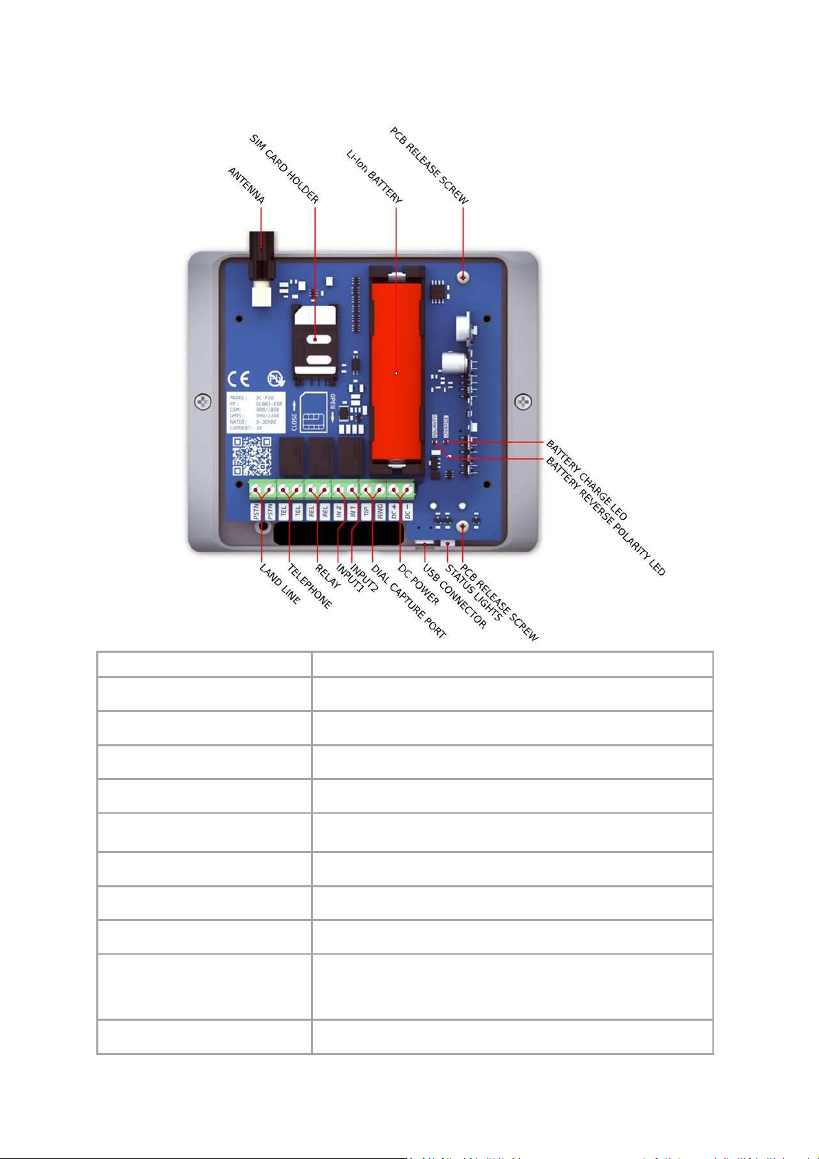
5. Device Configuration
ANTENNA
SIM C
ARD HOLDER
Li-Ion
BATTERY
(optional
)
DC P
OWE
R (DC+/DC
-)
D
IAL CAPTURE PORT
I
NPUT
S (IN1, IN2)
RELAY OUTPUT
(REL)
TELEPHONE
(TEL/TEL)
LANDL
INE
(PSTN/PSTN)
USB
C
ONNECTOR
Part Description
UMTS / GSM network antenna
Connector: SMA, Impedance: 50 ohm, Frequency: 900/1800/2100 MHz
For mobile network connection
Type: M2M data card, Dimension: 2FF mini SIM
Backup power supply
In case of power supply outage or sabotage. Type: SANYO UR18650F
Main power supply
Rated voltage: DC 9-30V, Rated current: max. 1A
Simulated landline for the alarm control panel’s TIP/RING input
(TIP/RING)
Line voltage: 48V, Loop current: 25mA, Impedance: 300ohm
Contact inputs (to DC-) for transmission of the signal of external
switches
Remotely controlled relay contact
Maximum voltage: 48 VAC, Maximum current: 2A
Landline output for home desktop phone
Polarity independent.
Backup PSTN line input
If the communication to both monitoring receivers fails, the
communicator will switch to the backup landline.
Polarity independent.
For parameters setting, the communicator must be connected to the
computer through USB port. Type: USB mini-B
Page 5

6. Status LED signals
Red flashing
Red constant
Yellow flashing
Yellow constant
Green
flashing
Green
constant
Blue
flashing
Blue
constant
IP
address
Port
Protocol
T
est period
SIM
PIN code
APN
User name
Password
7. Before You Start
SIM card is missing or the given PIN code is incorrect
Signal strength of the antenna is under 20%
Data link is OK, but APN is incorrect or missing IP address/Port
Data link is OK, but the receiver is still not responding
Idle mode, any receiver is available
Sending test report
Alarm control panel is on hook or dialing
Sending CID signals to the monitoring station
7.1 Monitoring Receiver
Make sure that the monitoring receiver is equipped with the system that allows receiving SIA DC-09
IP protocol messages before you start using SC-F3G and the following information should be
obtained.
7.2 GPRS/3G SIM Card and APN
For using the SC-F3G device a GPRS/3G SIM card is needed. During the configuration you need to add
the APN (Access Point Name) of the GPRS/3G SIM card and the following possible configuration
parameters.
Page 6
8. Setting SC-F3G
8.1 Installing the 3G DATA Setup application
The installation file of 3G DATA Setup application can be found on the flash drive of the device.
Installation steps:
1. Connect the SC-F3G communicator to the computer with the USB cable which can be found
in the package
2. After the computer recognized the device as a normal flash drive, select and copy the
3G_DATA_setup.exe to the PC
3. Run the 3G_DATA_setup.exe
4. If it is needed, install the proper version of .NET Framework
(Prompt up window will warn you)
NOTE: The configuration software is running only on MS Windows 7 operating systems or above!
9. Configuring SC-F3G
USB connection steps:
1. Run the 3G_DATA_setup application
2. Connect the SC-F3G communicator to the computer with the USB cable which can be found
in the package
3. The application verifies the USB connection
4. If the connection is established successfully, the application loads the stored configuration
and module status from the device
9.1 Information and Administration Area
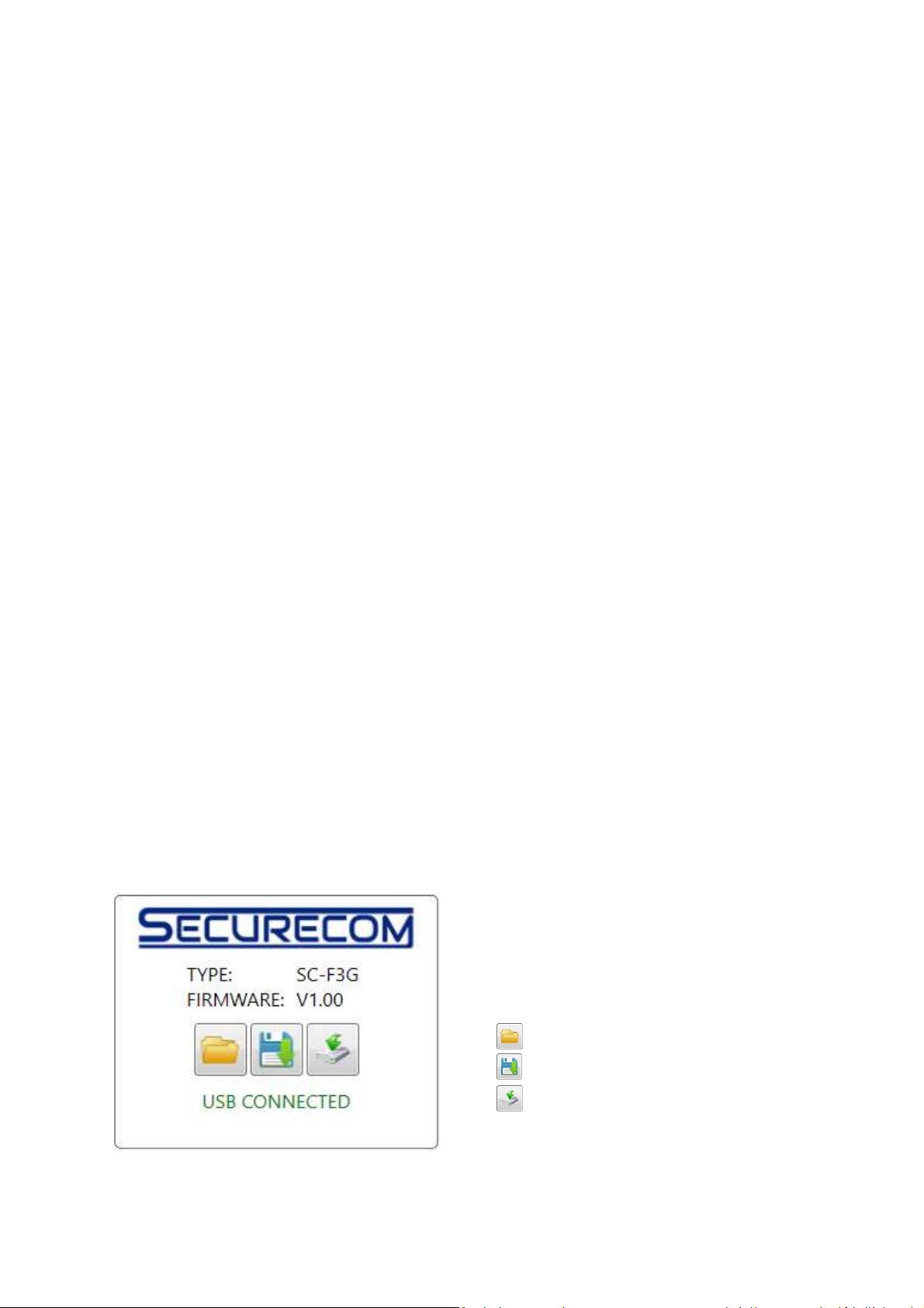
Manufacturer logo: SECURECOM
Product type with network standard (Europe / North
America): SC-F3G EUR
Firmware version: V1.00
Open previously saved configuration.
Save the current configuration into a file.
Load the configuration into the device memory.
USB connection status
Page 7
9.2 Module Status
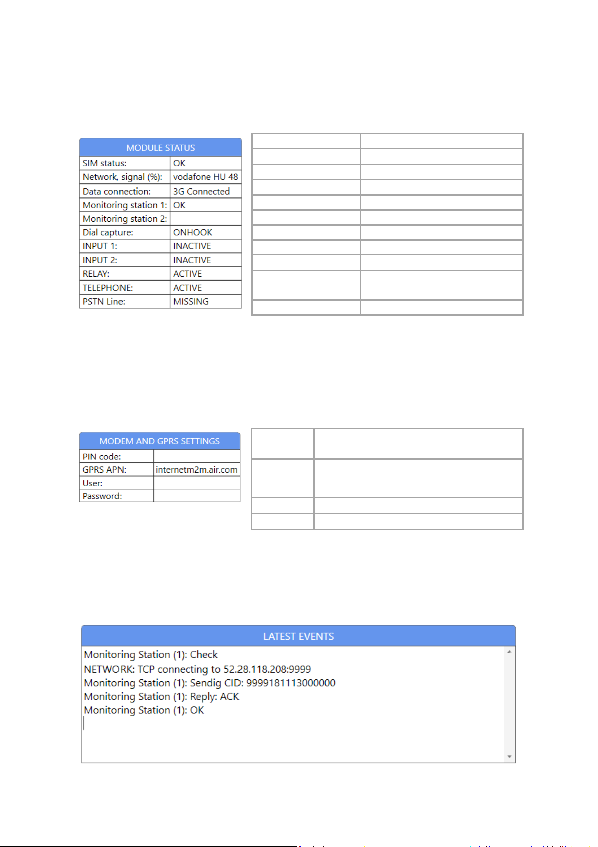
SIM status
Network, signal (%)
Data connection
Monit
oring station 1
Monitoring station 2
Dial capture
INPUT 1
INPUT 2
RELAY
TELEPHONE
PSTN Line
PIN code
GPRS APN
User
Password
Wait for SIM / OK / PIN request
3G/2G signal strength 1(0-100%)
WCDMA / GPRS data connection
Connection status of MS1
Connection status of MS2
Status of the dial capture hook
Status of INPUT 1: Active – Inactive
Status of INPUT 2: Active – Inactive
Status of Relay: Active – Inactive
Status of outgoing Telephone line:
Active – Inactive
Status of incoming PSTN landline
1
The transmission is stable in case of minimum 30% signal strength. If the signal strength is lower
than 30%, move the device to another place where the signal strength is higher.
9.3 Modem and GPRS Settings
The PIN code of the inserted SIM card can be
set, if the card is protected by PIN code.
The APN of the SIM card must be set, regardless
if it is using a public or non-public APN (Private
APN)
Add the user name for the APN if necessary
Add the password for the APN if necessary
9.4 Latest Events
In this window the communication events of the SC-F3G device can be tracked.
Page 8
9.5 Monitoring Station Settings
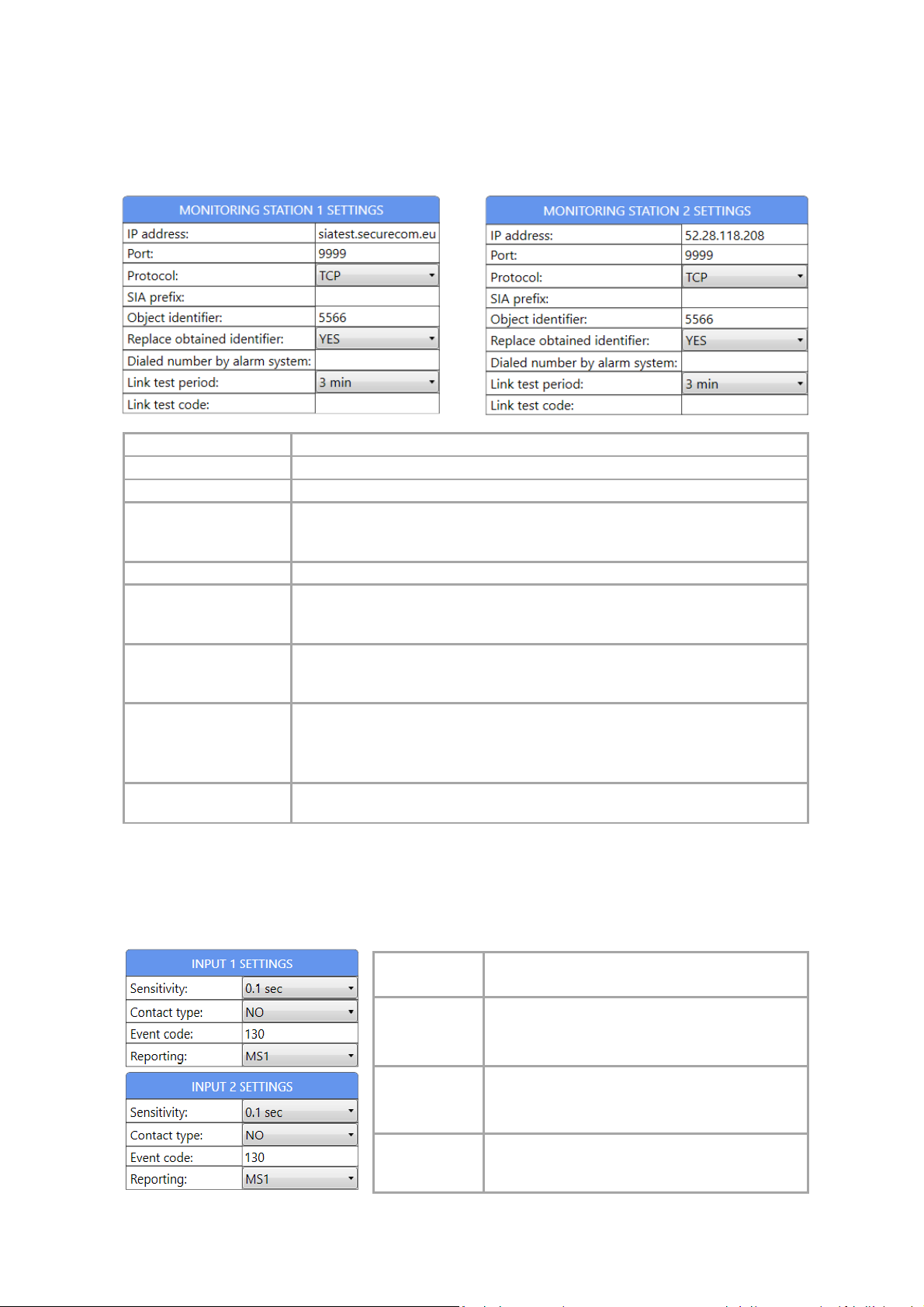
IP address
Port
Protocol
SIA prefix
Object identifier
Replace
Dialed number
Link test period
Link test code
Sensitivity
Contact type
Event code
Reporting
The communication settings of the monitoring stations can be configured.
IP address or domain name of the monitoring station
Port number of the monitoring station’s IP address
Selectable communication IP protocol: TCP, UDP
2 characters long SIA prefix, it can be used if the identifier of the connected
alarm control panel is just 4 characters long, but the necessary identifier of
receiver is 6 characters long
The self identifier of the SC-F3G device (4 characters long).
If it is enabled than the SC-F3G exchange the alarm control panel’s identifier,
obtained identifier
by alarm system
to given self object identifier.
YES: exchange, NO: not change
The communicator forwards the signal in case of the alarm system is dialing
this number. If this field is empty than the communicator forwards the signals
independently of the dialed number by the alarm system.
Sending test report to the monitoring station
• NO: test report is not sent
• 30sec – 24 hours: the device sends test reports to the monitoring
station by the given interval
Any code can be defined. If this field is empty than the communicator sends
Null Message, as defined by standard.
9.6 Input Settings
The triggered input event destination can be selected.
The switching time of the INPUT 1 and INPUT 2
can be set from 0.1 sec up to 10 minutes
Physical setting.
• NO – Normally Open
• NC – Normally Close
The Contact ID code of the triggered event can
be set. If the field stays blank than the input will
be inactive.
The triggered input event destination can be
selected. MS1, MS2, MS1 or MS2
Page 9
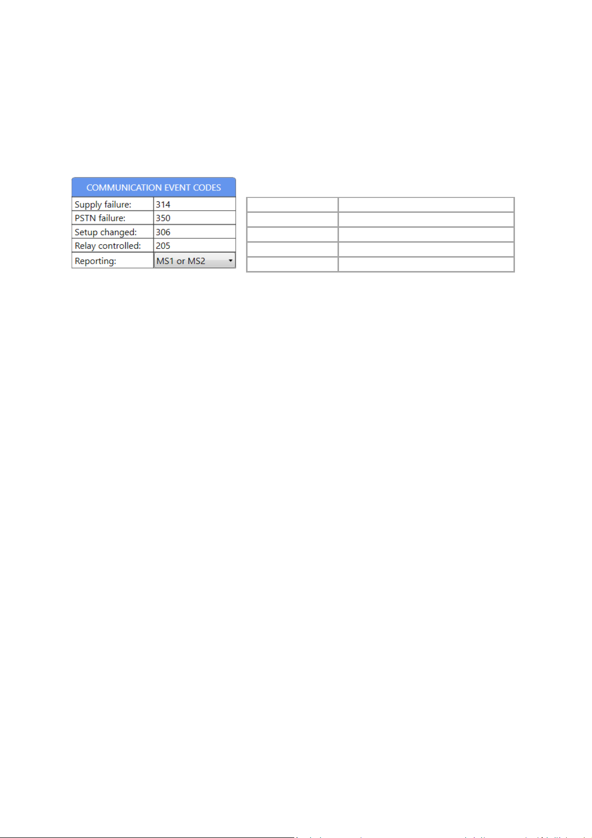
9.7 Status Event Codes
S
upply failure
PSTN failure
Setup changed
Relay controlled
Reporting
Setting the Contact IDs for the communicator’s own events. The event codes are standard 3
characters long ( 1 and 3, for “event” and „restore” are added automatically). If the event code field
is blank, the event is not sent to the monitoring station.
Power supply is damaged or failed.
PSTN is failed or disconnected.
The settings have been changed.
Relay has been controlled.
Destination receiver can be selected.
10. Signal Transmission
10.1 Description of the Signal Transmission
The signal transmission between the alarm control panel and the monitoring station through the SCF3G communicator works with following steps:
• The alarm control panel is dialing (over TIP/RING line) a preset phone number (e.g. 1111)
• The communicator detects the dialing and sends back the Handshake signal to the alarm
control panel
• The alarm control panel sends the Contact ID of the first event code
• The communicator receives and converts the signals to digital format and forwards it to the
active IP address of the monitoring station then waiting for the acknowledge message.
• The alarm control panel repeat the first Contact ID signal due the missing response of the
communicator (the transmission time of the network is around 1-3 seconds)
• If the communicator receives the sign of the successful message sent by the IP receiver, it
sends Kissoff sign (over TIP/RING line) as a response for the alarm control panel’s repeated
signal and it is recorded as successful event.
• The process restarts by sending the upcoming event code or the process is finished and the
alarm control panel hangs up the line.
Page 10

10.2 Signal Transmission Logic
Activates the
REL/REL
relay output
.
If both monitoring stations are entered, the direction if signal sending can be:
• Automatic: MS1 receiver is the primary, MS2 is the secondary, and every signal is forwarded
to the MS1 until it is available. If MS1 is unavailable, every signal is forwarded to MS2. As the
MS1 receiver will be available, so the test report is sent by MS1, it becomes primary again.
NOTE: This function is working if the field “Dialed number by alarm system” is empty!
• Custom: You can define a number for both monitoring stations which is dialed by the alarm
system. Using this option the alarm system will choose the specific receiver based on its
dialing order independently of the availability of the receivers.
NOTE: This function is working if the Dialed number by alarm system filed is NOT empty!
10.3 Backup PSTN Line Operation
If the monitoring stations are unavailable via GPRS/3G network the communicator switches to PSTN
line. In that case the line voltage is ended on TELEPHONE output, and the landline is only available for
the alarm system. If any of the set receivers (MS1 or MS2) is available again, the communicator
switches back to mobile network. In case of failure or power supply loss the basic communication
way is the PSTN. The condition of PSTN line usage is that the phone line must be connected!
11. Controlling Output
The relay output can be controlled by SMS commands.
REL=period#
NOTE: It is possible to control the relay outputs by smartphone application, which requires a service
with a monthly fee. Please contact to your distributor for further information!
Period values: 1-100 (seconds)
The basic state of the relay is NO (Normally
Open)
Page 11
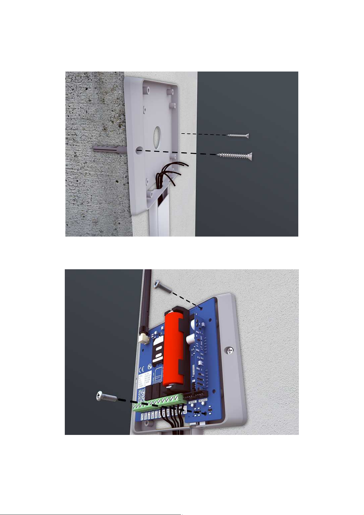
12. Mounting
1. step: Fixing the back plastic back plate
2. step: Panel fixing and wiring
Page 12
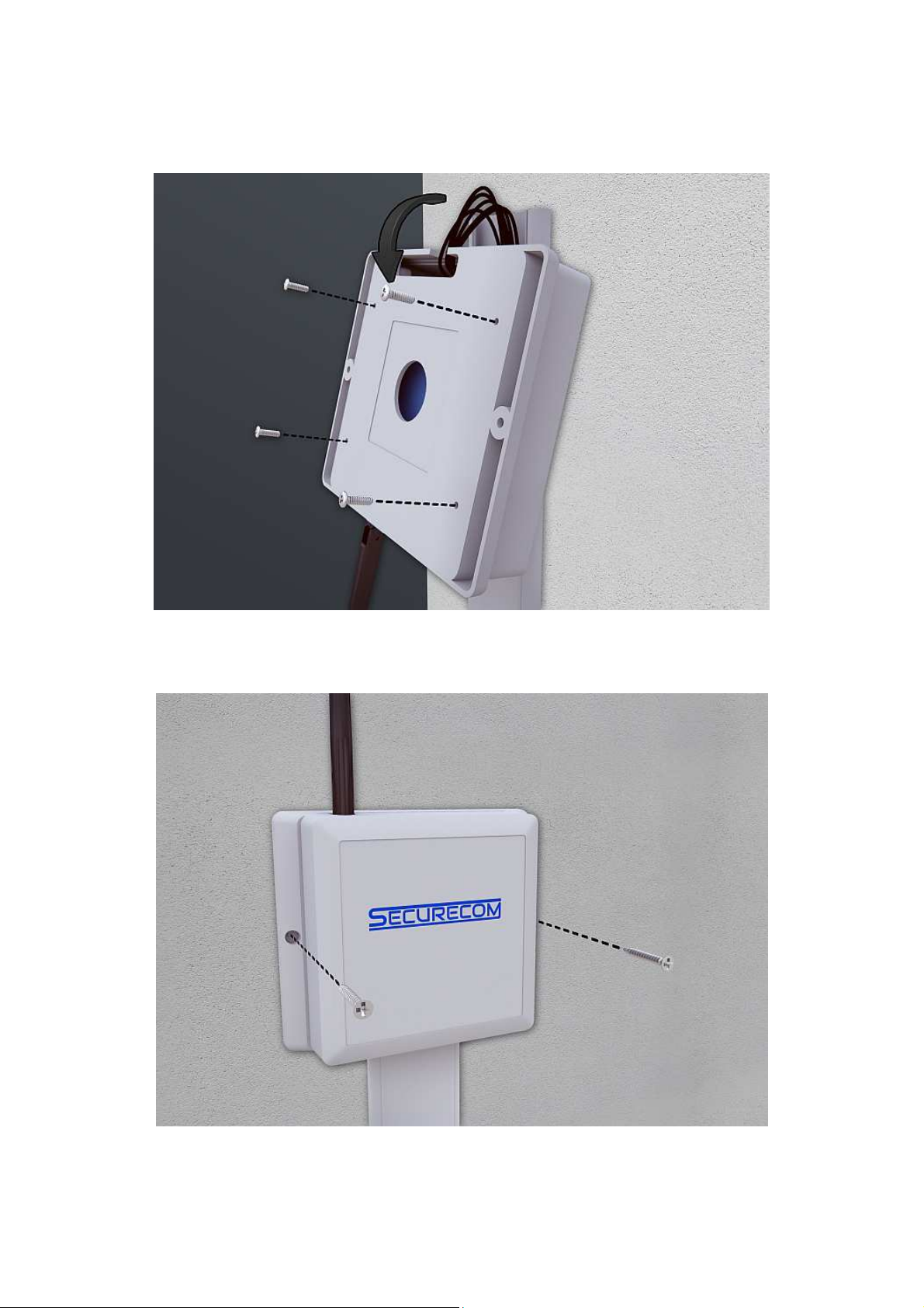
3. step: Releasing the wall fixing screw, flipping for the front plastic case fixing and screwing
4. step: Wall fixing with plastic cover
Page 13
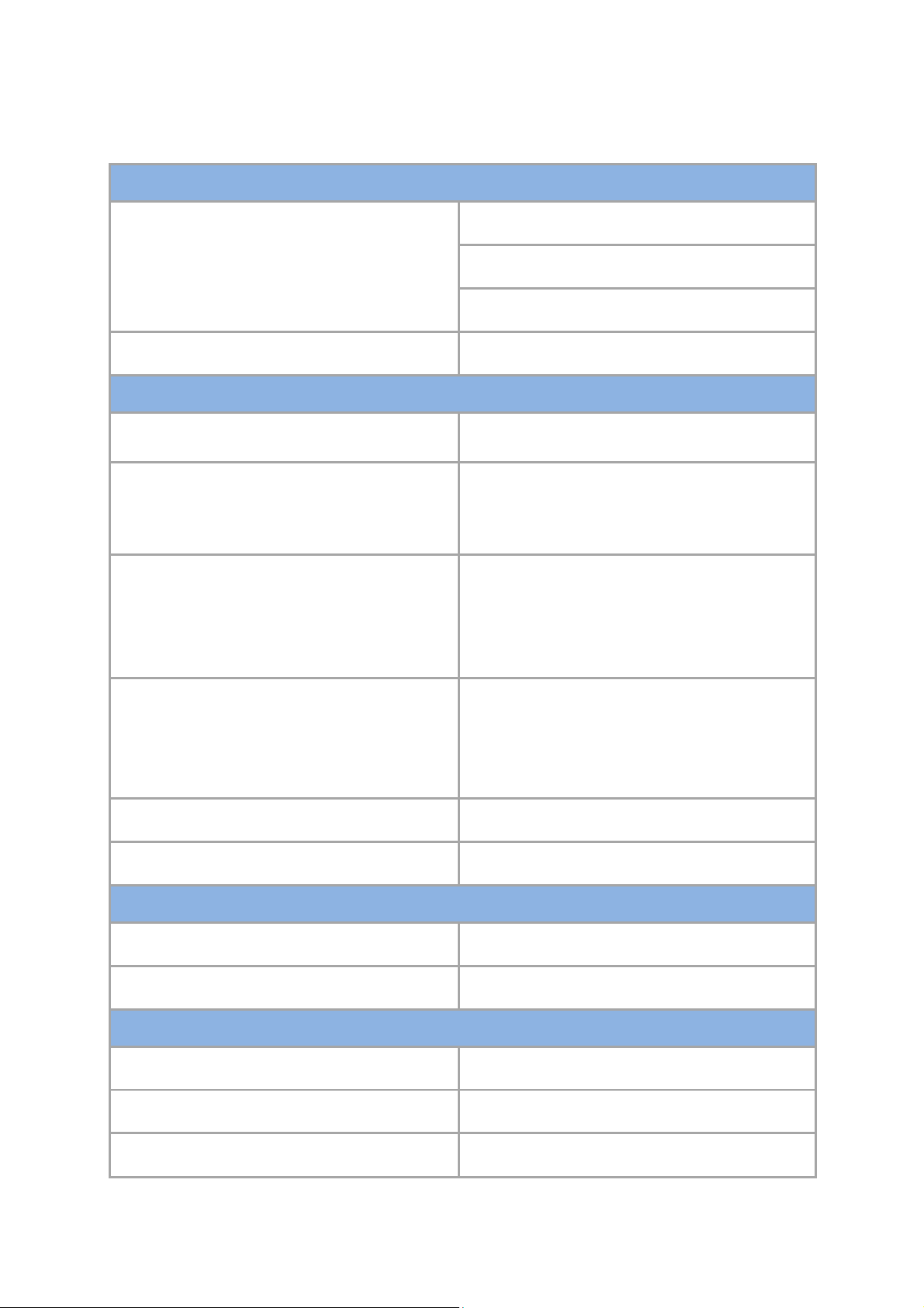
13. Technical Details
Two wire interface via terminal block
Transmission paths
3G UMTS DATA
(GPRS / EDGE / WCDMA)
(4G LTE optional)
PSTN landline backup
Alarm transmission
Interface application to monitoring software
Dial capture interface to alarm panel
PIN Inputs interface to alarm panel
(contact and voltage type in paralell mode)
Freq. Bands 2G: 900/1800MHz
Freq. Bands 3G: 900/2100MHz
Antenna: 3G SMA male
SECURECOM
Line voltage: 48V
Loop current: 25mA
Load impedance: 100-470 Ohm
Contact type: INPUT to DCexternal pull-down impedance < 100 Ohm
Voltage type: INPUT to DCexternal voltage trigger treshold > 5V (max. 30V)
S2S
interface (SIA to Sur-Gard)
Alarm protocols Dial capture side:
SIA DC-05-1999: Contact ID Protocol
3G IP connection side:
SIA DC-09-2013: Internet Protocol
Faults reported to monitoring centre External power supply failure, PSTN failure
Self events reported to monitoring centre Setup changed, Relay controlled
Relay outputs
Maximum operating voltage 60V DC
Maximum current rating 2A
Power supply
Supply voltage 9-24V DC
Maximum current 1A @ 12V DC
Nominal current 100mA @ 12V DC
 Loading...