

Page 1

SSP 302
Socket Energy Monitor
User and Installation
Instructions
BGX501-921-01
Page 2

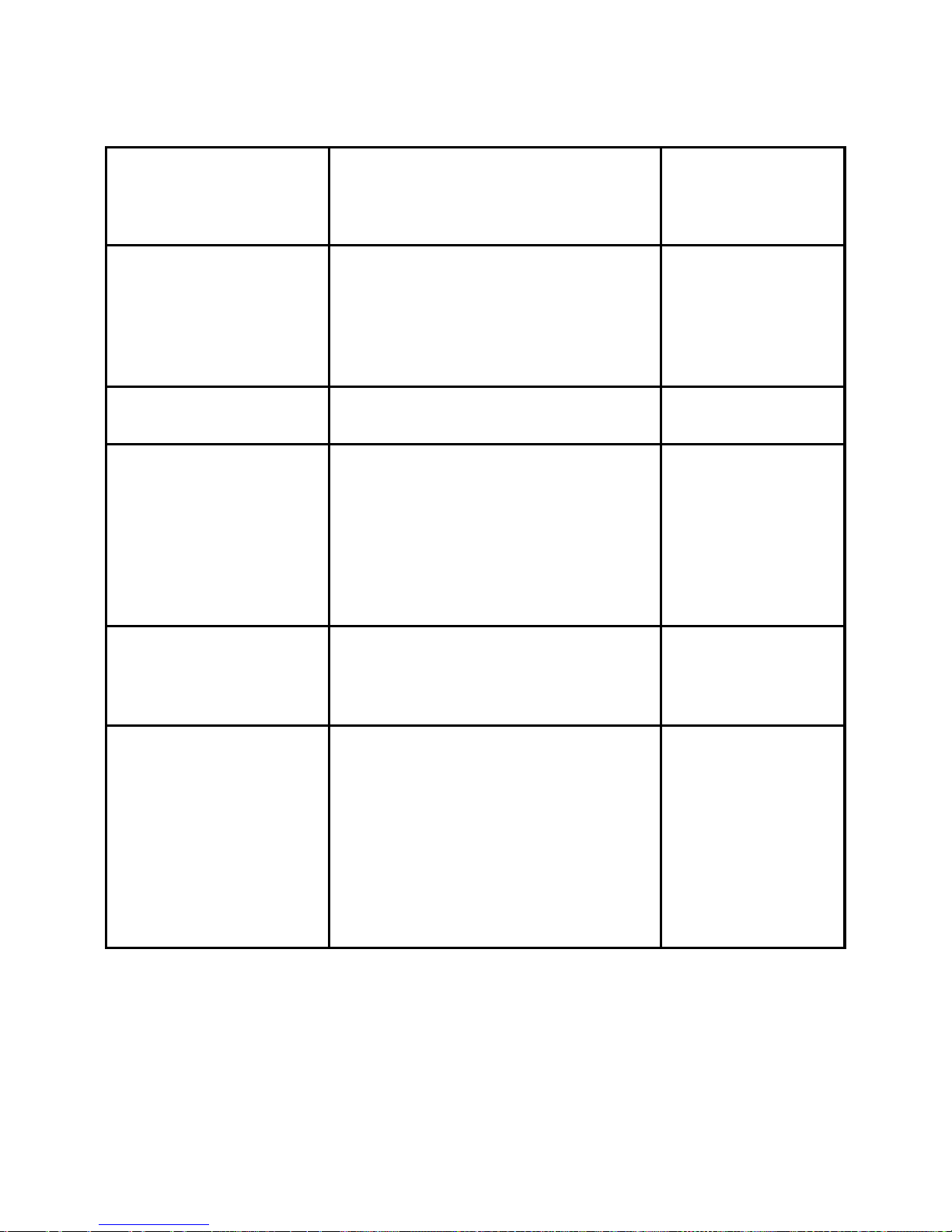
out of range
controller cannot
commu nicate directly
with device
SSP Repeater
Z-Wave
Controller
Lamp Load
Secure SSP 302
So cket Energy Monitor
T he Secure SSP 302 forms p ar t of
a Z-Wave Pl us™ home automation
network.
SSP 302 is a mains-powered,
plug-in device that supports energy
monitoring. It is suita ble for
switching loads up t o 3kW at 230V
AC. It can measure voltage,
Page 3

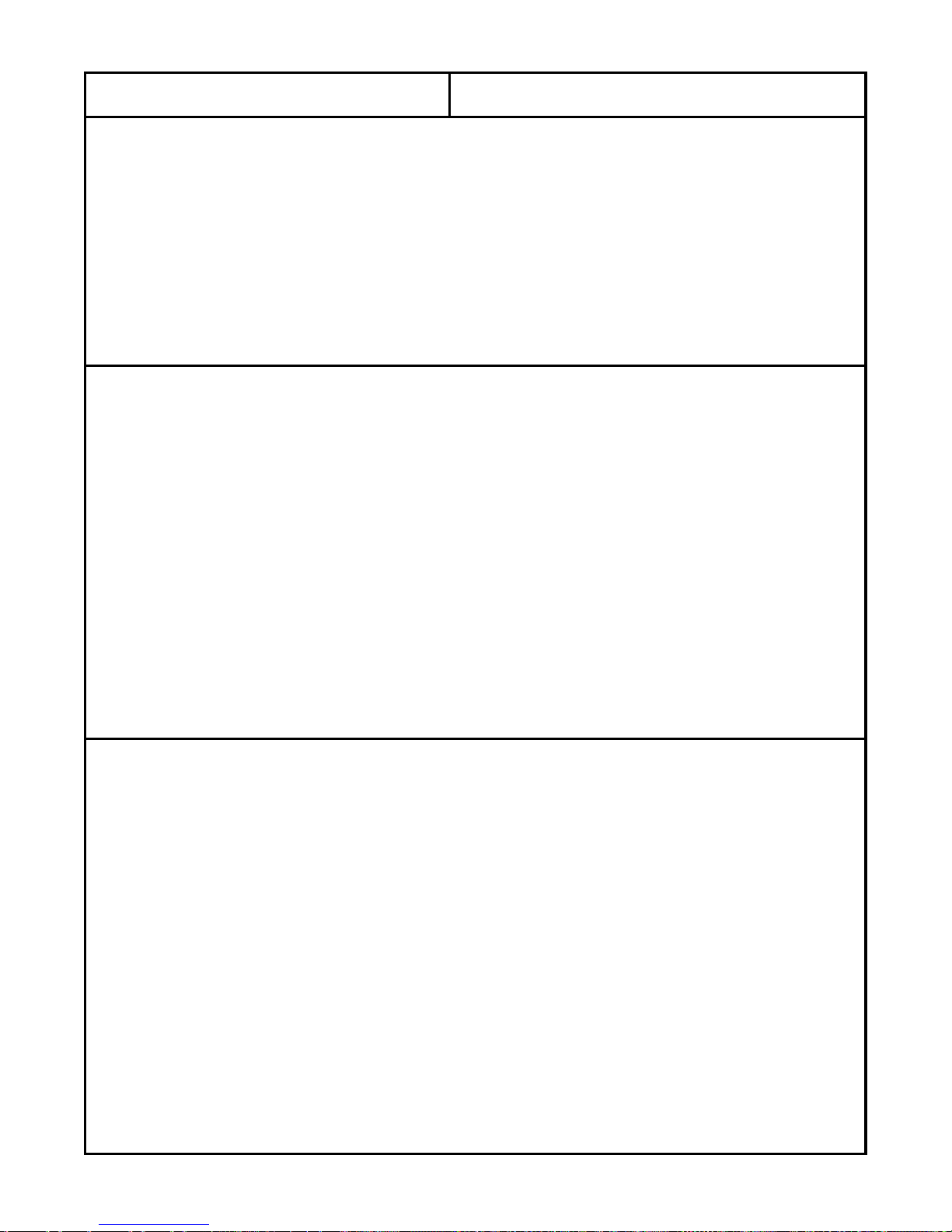
Button
F
L
A
S
H
curre nt, power, energy etc. The
SSP 302 acts as a repeater in a
Z-Wave network and helps other
de vice me ssage s to reach a
destination.
SSP 302 is a fully compliant
Z-Wave P lus™ device that will
wor k with other manufacturer’s
Z-Wave devices.
Installation
St ep 1:
Unpack and
insert t he
SSP 302 into
the wall socke t .
Ensure that the
red-coloured
ne twork status
3
Page 4

LED is flash ing (once per se cond) .
Note:
If th e network status LED is not
flashing check the following.
• Ensure wall socket s witch is on.
• Press the top button, the relay
status LED should switch ON
and g low green.
• If the r elay stat us LED does not
glow then t he device is not
functioning.
• It is possible that the SS P 302
was par t (joined) of another
n etwork prev io usly; i f so, exclude
it before including it in this
n etwork. R efer to step -2 for the
excl usion process.
Page 5

Avoid locations alongside or behind
large me ta l s urface s tha t could
interfere with the lo w power radio
signals between the unit and the
controller.
Step-2 : Z -Wave Plus™
commissioning
To incl ude the
SSP 302 onto
a network, put t he
controller into
inclusion mode .
Now, press and
hold the button on
SSP 302 for 4 to 7
seconds then
release. The network
F
L
A
S
H
F
L
A
S
H
5
Page 6

status LED will start flashing (twice
per s econd) on successful st art of
inclusion process.
Note: Refer to the controller’s
manual for con troller relevant
actions.
On suc cess ful inclu s io n t he LED
will turn off.
T he to tal process can take up to 2 0
s econds (Refer to the “Technical
specifications – Radio” section for
details).
If the dev i ce fails to join the
network it will go back to factory
defaul t stat e and the Network
status LED will start fl ashing once
per s econd.
Page 7

If there is an issue with RF
Communication, then re-locate the
device and repe at the
c ommissionin g proc ess again.
To exclude the SSP 302 from a
ne twork, pu t the controlle r into
ex clusion mode (refer to controller
instructions) and follow the same
sequence as per the
commissioning proce ss for include
node. After successful exclusi on
the network stat us LED will start
flashing once per s eco nd, a nd the
d evice w il l res et to facto r y defaul t.
If e x clusion fails, SSP 302 netw ork
status LED will turn off aft er about
5 seconds.
7
Page 8

Note: Exclusio n work s when the
d evice is i n direct range wi th the
controller ( no repeater all owed).
Associating SSP 302 in a
Z-Wave Netw ork
(follow steps 3 to 5)
Note: Association proc ess works
o nly after device includ ed onto
network.
Step 3: P ut the controller into
Associati on Mode.
Note: S ome control lers ca n
automati cally associate. Always
check with the m anufactur er’s
manual.
Step 4: Press and hold the
SSP 302 button for more than 1
Page 9

second, but less than 4 seconds,
and then re lease.
Step 5: The cont roller wi ll conf irm
association when t he process is
succe ssfu l ly co mple te d.
9
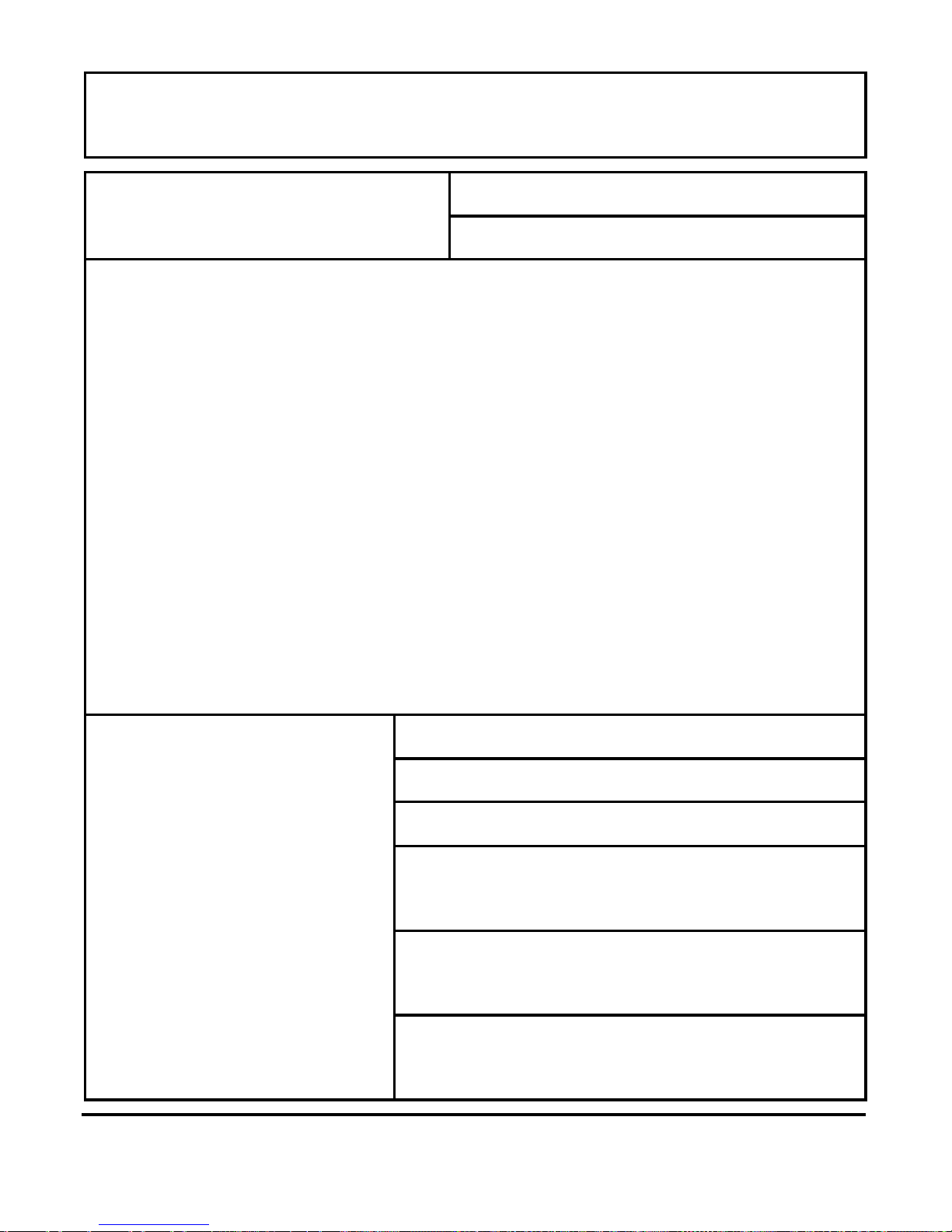
Page 10

Combined
Button & LE Ds
Green LED: ON
power switched to
front socket
Green
LED
*Socket type
w ill va r y wit h
country
A ppliance Socket
Press the SSP 302 button (less
than one second) to suppl y power
to its socket. By def ault , th e green
LED will be lit when the supply i s
On.
Page 11

The socket type will vary wit h
country. The figure shows t he UK
variant.
Ensure that th e appliance pl ug is
firmly p lugged in to the appliance
socket.
Over Current Protection
If t he current exceeds the limit for
mor e than 30 seconds t he l oad will
b e disconnected. To reconnect, the
user needs to press the button or
se nd an ON co mmand ove r the
Z-Wave link. The limit for each
country plug type is shown below:
UK: 13.5A
EU: 16.5A
ANZ: 10.5A
11
Page 12

Metering
The S SP 302 is a met erin g device
that provides the following
electrical par amet ers w i th an
accuracy of ±2%, or better, fr om
23W to full load, and less than
0.5W from 1W to 23W:
1. Voltage
2. Current
3. Acti ve power
4. Apparent Power
5. Active Ener gy
6. Apparent Energy
7. Power Factor
Page 13

Energy Save Mode
If the cur re nt is less than the
standby curre nt for 30 seconds , the
load wil l be dis connected to sav e
energy ( refer to the configuration
parameter 16 of Configuration
parameters table for how to
configure standby current).
13
Page 14
Button Actions
Press time Operation
LED
status
Less than 1
second
Toggles supply to
socket outlet
Toggles
green
LED
1-4 seconds
Association
NA
4-7 seconds
Inclusion/
exclusion
Red LED
flashes
twice per
second
7-11
Seconds
Resets device data NA
11-15
seconds
SSP 302 resets to
factory default
(only
available for up to
60 seconds from
power up
Red LED
flashes
once per
second
Page 15

Z-Wave Plus command
classes
Z-Wave Plus
Device
Classes
Implemented Device
Class
Generic
Binary Switch
Specific
Not used
Basic
Routing Slave
Supported Command class
Command Class
Commands
Supported
Basic CC (V1)
Get
Set
Report
Basic CC is mapped to binary switch CC
Binary switch (V1)
Get
Set
Report
Manufacturer
Specific (V2)
Get
Report
15
Page 16

Manufacturer ID =
0x0059
Product Type ID =
0x0011
Product ID = 0x0001
(UK & EU)
Product ID = 0x0002
(ANZ)
Version (V2)
Get
Report
Version Command
Class Get
Version Command
Class Report
Association (V2)
Set
Get
Report
Remove
Supported Groupings
Get
Supported Groupings
Report
Specific Group Get
Command
Specific Group Report
Page 17

Command
Product supports five association groups and
group 1 to 4 are having maximum of 4 nodes
and group 5 is having one association node.
Configuration (V1)
Set
Get
Report
See Configuration Parameters for details
Device Locally
Reset (V1)
Report
Power cycle the device and press and hold the
button for more than 11 seconds and less than
15 seconds within the 60 seconds of power
cycle to put the device in factory default, that
include setting all the configuration, Association
to factory default and removing the device from
Z-Wave network.
Association Group
Info (V1)
Group Name Get
Group Name Report
Group I nfo get
Group I nfo Report
Group Command List
Get
Group Command List
17
Page 18
Report
Association group Name:
Group1 : Lifeline
Group2: Power
Group3: Electrical Parameter
Group4: Rel a y Status
Group5: Time
Profile MSB:
ASSOCIATION_GROUP_INFO_REPORT_P
ROFILE_GENERAL
Profile LSB:
Group1: 0x01
Group2: 0x02
Group3: 0x03
Group4: 0x04
Group5: 0x05
Supported Command class and command :
Group 1: to Group3:
CC: COMMAND_CLASS_METER_V3
Command: METER_REPORT
Group4:
CC:
COMMAND_CLASS_SWITCH_BINARY
Command : SWITCH_BINARY_REPORT
Group5:
CC: COMMAND_CLASS_TIME
Page 19
Command: TIME_GET, DATE_GET
Z-Wave Plus Info
(V2)
Get
Report
Role Type:
ZWAVEPLUS_INFO_REPORT_ROLE_TYPE_SLAVE_
ALWAYS_ON
Node Type:
ZWAVEPLUS_INFO_REPORT_NODE_TYPE_ZWAVE
PLUS_NODE
Installer Icon:
ICON_TYPE_GENERIC_ON_OFF_POWER_SWITCH
User Icon-
ICON_TYPE_GENERIC_ON_OFF_POWER_SWITCH
Power Level
(V1)
Power Level Set
Power Level Get
Power Level Report
Power Level Test Node
Set
Power Level Test Node
Get
Power Level Test Node
Report
19
Page 20

Meter (V3)
Get
Report
Supported Get
Supported Report
Meter Reset
Meter table
Monitor (V1)
ID Get
ID Report
Capability Get
Capability Report
Current Data Get
Current Data Report
Meter Table
Configuration
(V1)
Meter Table Point Adm
Number Set Command
CRC-16
Encapsulation
(V1)
CRC-16 Encapsulated
Command
Page 21

Control led Command class
Time (V1)
Time Get
Time Report
Data Get
Date Report
Although the S SP 302 is a metering device, it
does not have its own real time clock and
needs to get time from another device in the
network. Therefore, there should be one
device in the network that has real time clock
and supports time command class. Once the
SSP 302 has received the time, it will sta rt
logging the historical data. The SSP 302 wil l
continue metering even without time
synchronisation.
Note: For more information about Z-Wave
command classes and their use refer to
“SDS12652 Z-Wave Command Class
Specification” version 3 or above and
“SDS12657 Z-Wave Command Class
Specification” version 2 or above.
21
Page 22

Configuration parameters
No
Parameter
Report
Unit
Size
Byte (s)
Resolution
Max
Value
Default
Value
Parameters 1 to 7 delta based
configuration
1
Switch
Status
NA 1 NA 1 0
2
Voltage
V
2
0.1
60
0
3
Current
A
2
0.01
15
0
4
Power
Factor
% 2 0.1 100 0
5
Active
Power
W 2 1 4000
0
6
Active
Energy
W 2 1 32K 0
7
Apparent
Energy
VA 2 1 32K 0
Page 23

When delta need to set then first it should be
converted from engineering value to
configuration value using this formula for
calculating configuration values =
Engineering Value/Resolution,
e.g. Voltage Delta 10V = 10/0.1 = 100
e.g. Current Delta 5A = 5/0.01 = 500
e.g. Power Factor 10% = 10/0.1 = 100
e.g. Power/Energy 100W = 100/1 = 100
Parameters 8 to 14
time interval based configuration
8
Switch
Status
Sec
2 1
65520
0
9
Voltage
Sec
2
1
65520
0
10
Current
Sec
2
1
65520
0
11
Power
Factor
Sec
2 1
65520
0
12
Active
Power
Sec
2 1
65520
0
13
Active
Energy
Sec
2 1
65520
0
14
Apparent
Energy
Sec
2 1
65520
0
23
Page 24

Controllers may only allo w configuring signed
values. In order to set values in the range
32768…65520, the value sent in the application
shall be equal to desired value minus 65536. For
example, to set time interval to 36000 seconds it
may be needed to set a value
36000−65536=−29536.
Parameters 15 to 16 general configuration
15
Relay
and
LED
config
NA 1 NA 3 0
Refer Table “Relay and LED
configuration” for details.
16
Sleep
Current
Config
A 2 0.001
1 0
example of sleep current
0.5A = 0.5/.001 = 500
Page 25

.Common attributes:
-
Min Value = 0
-
Zero configurations means that
the corresponding
functionality is
disabled.
-
Value set more than maximum
allowable limit will be rejected
silently
, and SSP 302 will retain it
last configuration value.
IMPORTANT: when any configuration is set,
then it shall be recommended that user
should read back and verify the correctness
of set configuration value.
Rel ay and LED confi guration
Config
Value
Relay
Status
After
Power
Cycle
LED Status
0
Open
ON for Relay
Close
OFF for Relay
Open
25
Page 26

1
Retain last
status over
the power
cycle
ON for Relay
Close
OFF for Relay
Open
2
Open
ON for Relay
Open
OFF for Relay
Close
3
Retain last
status over
the power
cycle
ON for Relay
Open
OFF for Relay
Close
SSP 302 is shipped with zero default relay
LED configuration
Visual Indication of a
Communicat io n F ail ure
The SSP 302 can indicate a
communication failure state to the
en d user in t he follo wing s i tu ation:
if t he SS P 302 is config ured wi th
TIME-INTERVAL based data
Page 27

reporting (Confi guration
p arameters #8 t o #14) and at least
one node is associat ed to it.
In tha t situa tion, if there is n o
Communication Acknowledge with
a ny ass ociated dev ic e in t he
ne twork fo r more than one hour the
devi c e wi ll in dic a te a
c ommunicat io n fai l status. T he
c ommunicat io n fai l status wi ll b e
represented on the device by the
continuous glowi ng of the net work
status LED. When th e device
establishes communication with
any associated node i n the net work
it w il l come out of the
communication fail state.
27
Page 28

Technical specifications
Electrical
Purpose of
Control:
Electrical control
Supply:
230V±10% AC, 50Hz
Current rating:
UK
13(3)A, max
3kW
EU
16(3)A, max
3.6kW
ANZ
10(3)A, max
2.3kW
Control ty pe :
Micro-disconnection
Control action:
Type 1B
Software class:
Class A
Burden:
<1W in standby
Mechanical
Dimensions
(WxDxH) mm
UK:
60 x 61 x 119
EU:
60 x 95 x 119
ANZ:
60 x 69 x 119
Weight (single
unit packing):
UK:
250 ± 30 g
EU:
250 ± 30 g
ANZ:
240 ± 30 g
Page 29

Case material:
Thermoplastic,
flame retardant
After Care: Clean only with a clean damp
cloth – do not use any aggressive cleaning
agents. If cleaning agents are necessary,
check compatibility before use.
Mounting
UK
Type G
EU
“Schuko” Type E & F
ANZ
T ype I
Ball Pressure Test Temperature
75°C
Environmental
Im puls e vol tage
rating:
Cat II 2500V
Storage
temperature:
-20°C to 55°C
Operating
temperature:
0°C to 40°C
Environmental
humidity range:
0% to 95%
Atmospheric Range:
980 to 1035hPa
Pollution Degree:
Degree 2
Enclosure
protection:
IP30
29
Page 30

Radio
RF
frequency:
UK & EU: 868.42MHz
ANZ: 921.42MHz
RF range:
100m Line of sight in open air
Class:
3
Inclusion: If the Z-Wav e controller does
not respond within 2-seconds then the SSP
302 will try with NWI (Network Wise
Inclusion). The total process can take up to
20 seconds.
This is a Z-Wave certified product and can be
used with Z-Wave controllers that support its
functionality. Please refer to the
documentation provided by the gateway or
controller manufacturer. See the Z-Wave
alliance website www.z-wavealliance.org for
certified controllers.
Page 31

Compliance
HSR
O
EN 60730-1, RoHS, R&TTE directiv e
ETSI EN 300 220-2, BS 1363-3 (for UK)
IEC 60884-1 (for EU)
AS/NZS 3122 and RCM ACMA (for ANZ)
31
Page 32

Notes
Page 33

Notes
33
Page 34

European Head Office
Secure Controls (UK) Ltd.
South Bristol Business Park
Roman Farm Road
Bristol, BS4 1UP, UK
e: info@securetogether.com
www.securetogether.com
European Sales Office
CEWE Instrument AB
Box 1006, 611 31 Nyköping
t: +46 8 600 80 60
e: info@securetogether.com
www.securetogether.com
Page 35

Australia Sales Off ice
Secure Australasia Pty Ltd
258 Darebin Road
Fairfield VIC 3078
Australia
p: +61 3 9485 6000
f: +61 3 9485 6099
e: info@securetogether.com
www.securetogether.com
Secure Meters Ltd
Pratapna gar Industr ial Area
Udaipur 313003
India
p: +91 294 2492 300-05
f: +91 294 2492 310
e: mktg@securetogether.com
www.securetogether.com
35
Page 36

Elegant Metering Solutions FZE
4EA 326, P.O. Box 54857
Dubai Airport Free Zone
Dubai, UAE
p: +971 50 6575166
f: +971 04 204 5619
e: emsfze@emsdxb.ae
www.securetogether.com
 Loading...