

Page 1

SCT007
INSTALLATION INSTRUCTIONS
The SCT007 can be programmed to create a
comfortable yet efficient environment in your home
INSTALLATION AND CONNECTION SHOULD ONLY
BE CARRIED OUT BY A SUITABLY QUALIFIED
PERSON AND IN ACCORDANCE WITH THE
CURRENT EDITION OF THE IEE WIRING
REGULATIONS
WARNING: ISOLATE MAINS SUPPLY BEFORE
COMMENCING INSTALLATION
1
7 Day Programmable Room Thermostat
Page 2

2
Please study the diagram opposite to familiarise yourself
with the mounting plate before commencing with the
installation
Terminal Cover Latch
Terminal Cover
Guide
Slots
Release
Button
Battery
Supports
Choosing allocation for your SCT007
The SCT007 should be mounted on an internal wall
approximately 1.5 meters from floor level and should be
in a position away from draughts, direct heat and
sunlight.
Ensure that there will be enough space to the right of the
mounting plate to allow easy access to the release
Page 3

FITTING THE MOUNTING PLATE
DIRECT WALL MOUNTING
The SCT007 as supplied is intended for direct wall
mounting.
A mounting plate is fitted to the back of the unit, this will
need to be removed before installation. To remove, press
the release button located on the right hand side of the unit
and gently pull the mounting plate away from the SCT007
body. The terminal cover on the mounting plate should
now be opened. Use a suitably sized screwdriver to open
the terminal cover latch (see diagram). This will expose the
connection terminals, middle fixing screw location and the
aperture through which all the wiring will enter the
mounting plate.
ELECTRICAL CONNECTIONS
The SCT007 is battery powered and therefore does not
require a mains supply. It also has voltage free contacts
which makes it suitable for controlling low voltage
systems.
The SCT007 is double insulated and therefore does not
require earthing. However continuity of existing earth
wiring should be maintained, this can be achieved by the
use of separate connectors, and any spare earth
conductors should be made electrically safe.
The recommended cable sizes are 1.0 mm or 1.5 mm. All
wiring should be completed prior to fitting the SCT007 to
the mounting plate. No conductors should protrude
outside of the area enclosed by the terminal cover. The
diagram below shows the internal connections for the
SCT007 and the typical wiring connections to the
mounting plate.
4 5V
L (LINE)
LOAD (HEAT)
LOAD (COOL)
N (PARKING)
1
2
3
4
3
Page 4

When all electrical connections are complete, close the
terminal cover allowing the cover to latch into place. The
terminal cover should now be secure.
FITTING THE SCT007
There are many applications for the SCT007. Example
circuit diagrams for some typical installations are shown
below. These diagrams are schematic and should be used
as a guide only.
Please ensure that all installations comply with the current
IEE regulations.
For reasons of space and clarity not every system has
been included and the diagrams have been simplified, for
instance some Earth connections have been omitted.
Other control components shown in the diagrams i.e.
Valves, RoomStats etc are general representations only.
However the wiring details can be applied to the
corresponding models of most manufactures.
Cylinder and Room Thermostat Key:
C = Common CALL = Call for heat or break on rise
SAT = Satisfied on rise N = Neutral
4
SCT007 controlling typical combination boiler installation.
For precise termination connection information please refer to the boiler
manufactures instructions
1 2
3
4
E
N
L
E
N
L
Remove link
if Fitted
COMBINATION BOILDER
TERMINALS
Mains
Supply
SCT007
Page 5
FITTING THE SCT007 (CONT.)
5
SCT007 wired to control a cooling load.
When necessary the SCT007 should be used in conjunction with a contactor.
1 2
3
4
N
L
E
N
L
Mains
Supply
SCT007
COOLING LOAD
N L
ON
OFF
ON
OFF
HOT
WATER
CENTRAL
HEATING
PUMP
&
BOILER
Programmer
SCT007
MAINS
SUPPLY
MAINS
SUPPLY
N
L
E
N
L
E
N
L
ROOM
STAT
ROOM
STAT
SAT
CALL
SAT
CALL
CYL
STAT
C CN
1 2 3 4
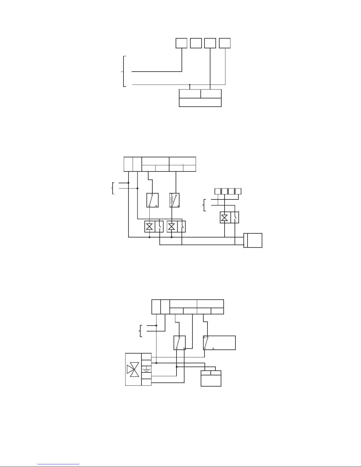
SCT007 controlling a secondary heating zone on a fully pumped system with
existing programmer and two spring return valves with auxiliary switches.
N L
ON
OFF
ON
OFF
HOT
WATER
CENTRAL
HEATING
PUMP
&
BOILER
Programmer
SCT007
MAINS
SUPPLY
N
L
E
N
CALLSAT
CALL
CYL
STAT
C
W
BL
0
GR
L
SAT
1
32
4
SCT007 replacing a conventional room thermostat on a fully pumped system
with an existing programmer and 3 port mid-position valve.
Page 6

FITTING THE SCT007 (CONT.)
6
SCT007 replacing a conventional room thermostat on a fully pumped system
with an existing programmer and two spring return valves with auxiliary
switches
N L
ON
OFF
ON
OFF
HOT
WATER
CENTRAL
HEATING
Programmer
SCT007
MAINS
SUPPLY
N
L
E
CALLSAT
CALL
CYL
STAT
C
SAT
1
32
4
PUMP
&
BOILER
N
L
If replacing an existing room thermostat with an accelerator heater, the
neutral wire should be put into terminal 4 of the SCT007. The programmer
should be left in situe to control Hot water, with Central heating programmed
to be ON constantly with control being taken over by the SCT007.
Ensure all dust and debris has been cleared away prior to
fitting the unit. Insert the 3 x AA size alkaline batteries
(supplied) into the back of the SCT007. Make sure they are
fitted correctly as shown on the label positioned between
the battery terminals. (see diagram below)
Back view of SCT007
Battery Terminals
Guide
Lugs
Once batteries have been fitted, offer the left hand side of
the unit up to the mounting plate ensuring that the two
guide lugs are fitted into the corresponding slots in the side
of the mounting plate. Now swing the right hand side of the
SCT007 up against the mounting plate until the release
button clicks into place.
PRESS ANY BUTTON ON THE UNIT TO ACTIVATE THE
DISPLAY
Page 7

GENERAL INFORMATION
7
Before handing over a new installation to the end user,
always verify that the system responds corretly on all
programmes (see User instructions) and that the other
electrically operated equipment and controls are
correctly adjusted.
Explain how to operate the unit to the user and hand
over the User operating instruction. The SCT007 is not
user serviceable except for the replacement of batteries.
SPECIFICATION
Contact type Micro dis-connection (Voltage free)
Contact rating 8(3) Amps 230-240 V AC
Power supply 3 x AA size alkaline batteries
Battery life In excess of 2 years
Operating voltage 3.5 - 4.75 V DC
Operating termperature 0 °C to 40 °C double insulated
range
Disrt protection Normal situations
Moisture protection Normal situations
Storage temperature -25 °C to +60 °C
Base material Thermoplastic, flame retardant
Mounting Directly to wall or onto a single or
double gang wiring box (to Bs4662
standard) by means of a patress
Dimensions 142 mm x 71 mm x 30 mm
Display Liquid crystal, two digit time and
temperature display and day of week
indicator
Clock 12 hour AM/PM
Display time adjustment 1 minute steps
Switched time adjustment 10 minutes steps
Target temperature 1°C
adjutment
Temperature control 5 °C - 30 °C
range
Temperature differential <0.5 °C
(Hysteresis) at 4°C
per hour
Temperature accuracy at 19.75 °C - 20.75 °C (Conventional wet
20 °C central heating system)
19.50 °C - 21.50 °C (Electric heating
up to 8 Amps)
Temperature settings 6 per day, independent seven day
programming
Override Permanent temperature lock until
reset, temporary temperature override
until next preset heating period.
Page 8

Cewe Instrument AB
611 31 Nyköping
Tel: +46 8 600 80 60
Email: info@securetogether.eu
Web Site: www.securetogether.eu
Box 1006
Part Number P84119 Issue Number 1
 Loading...