

Page 1
BP1: > 2 years
INSTALLATION
The BP1 detector provides the mo convenient and cost effective solution for security device is powerful and versatile enough to help solve even the
toughest, most labor intensive installation. The BP1 detector is compatible with wireless extension modules EXT116S or with built-in virtual modules EXT1 16SVM in P series control
panels P16, P32 and P64.
st reliable, protection. The
2
SECOLINK WIRELESS DETECTORS
SPECIFICATIONS
Model Passive infrared sensor (PIR sensor)
Dimensions (W x H x D) Ambient humidity
Built-in temperature sensor Pet immunity
Ambient temperature Battery
Battery life
BP1
59 mm x 110 mm x 46 mm
oo
-10 C - +55 C
0% - 70% Depends on firmware version of the detector: Lithium battery
½ AA, 3.6V
Operating frequency
1 = 868,30 MHz (EU)
9 = 915,30 MHz (AU)
3
Battery life of wireless detectors depends on the
environment, usage, and the specific wireless devices
being used. Factors such as humidity, high or low
temperatures, as well as large swings in temperature
may all reduce the actual battery life in a given
installation. When the battery is nearly dead, the
detector will send a low battery signal to the alarm
system for the user to replace it before it discharges
completely.
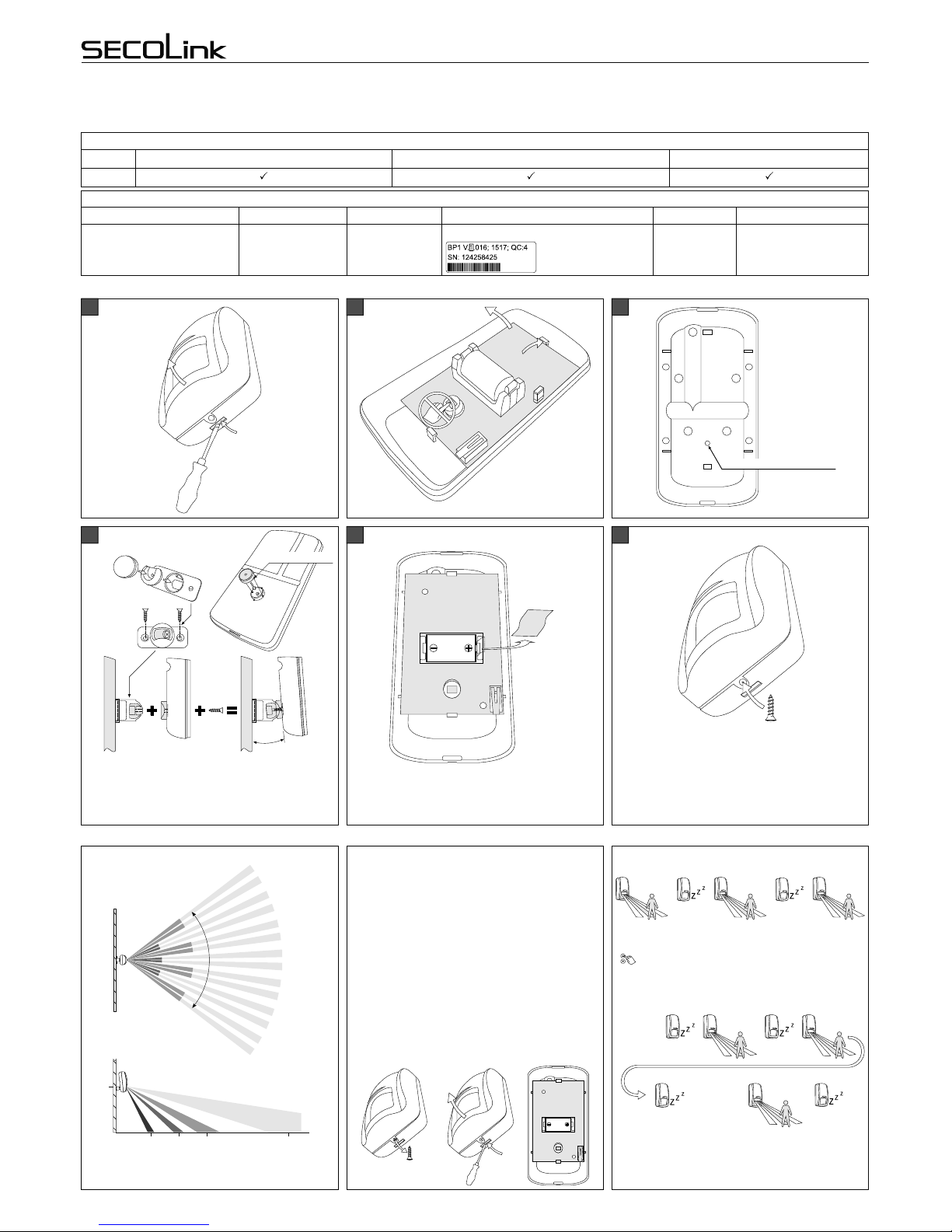
1. Unscrew the self-tapping screw.
2. Remove the detector's top cover .
3. Observe correct polarity and insert the battery into
the battery holder.
4. Close the top cover and secure it with a self-tapping
screw.
5. Dispos of used batteries as per local regulations.
Caution: the detector will send a tamper message to the
receiver when housing is opened - the alarm can be
triggered.
BATTERY INSTALLATION/REPLACEMENT WIRELESS DETECTOR OPERATION TESTINGDETECTION PATTERNS
1
2
1
Use for swivel mount bracket
54
Remove the plastic tab. Follow instructions on a 2nd
page and enroll the detector into the system.
6
Close the top cover after a successful detector's
enrollment into the alarm system. Use the supplied self-
tapping screw to secure the top cover to the mounting
base.
Pull the
plastic tab
2,1 m
1,9 m 3,3 m 5,9 m 15 m
Make sure that the angle between a wall and detector's
body meets the requirements.
o
78
Normally a wireless motion detector idles 4 minutes after
last movement detection:
~ 4 min ~ 4 min
< 4 min ~ 10 sec
~ 10 sec
Top view
Side view
TEST
STARTED
TEST
ENDED
~ 4 min
2
1
BP1 Wireless detector
Intruder alarm system
Installation manual
Alignment pins
o
~7
Assembly of the swivel mount
bracket pad
Tighten one part of the bracket to a wall, place detector's
bracket guide on the detector, and secure everything
with a screw. Make sure that the angle between a wall
and detector's body meets the requirements.
1
2
T o test wireless detector operation enable the test mode
by doing a burglary zone test:
Main menu }Test }Burglary zone test
Detector will enter the test mode after first movement
detection and will stay in this mode until the zone test will
end (see picture below).
Page 1
Page 2
Please act according to your local rules and do not dispose of your unusable alarm system or its components with other household waste. This
product utilization in EU is covered by European Directive 2002/96/EC.
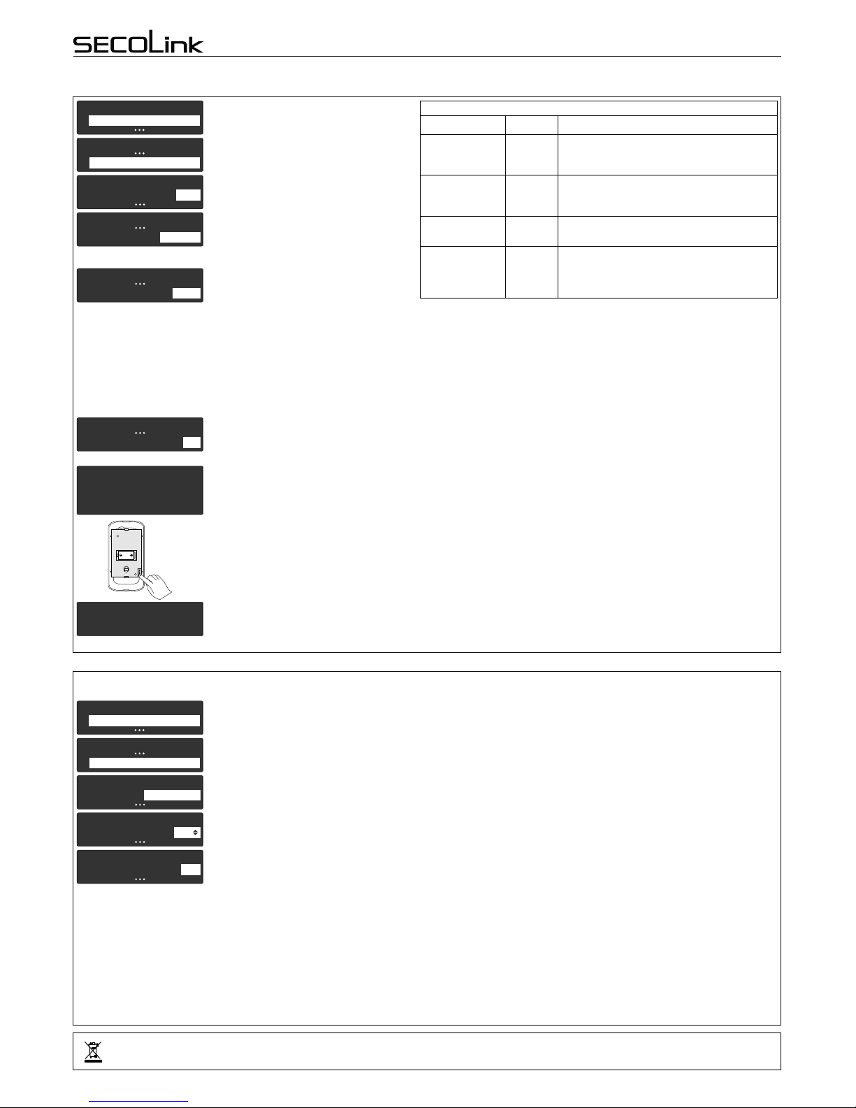
ENROLLING
Done
Wireless detector successfully enrolled. No
additional transmissions are needed for
confirmation.
BP1
Supports Wireless detector loop (zone) ID number
Passive infrared
sensor
(PIR sensor)
180
255
Built-in
temperature
sensor
Delete detector in
a specific zone
Delete all
detectors
in a specific
wireless module
All
All
181
254
BP1 Wireless detector
Intruder alarm system
Installation manual
BP1
Use
Wireless detector loop (zone) enrolling ID numbers
Change setting's Attenuation value to 3dB. Save
changes by pressing the [ENT] key.
Caution: Each wireless detector is supervised by a
check-in signal that is sent to the receiver at 60
minutes interval. During this check-in communication the detector will receive new settings and
will start to work according to them. DO NOT
FORGET to change the Attenuation setting's value
to Normal cond. when installation or maintenance
works are finished.
IMMUNITY TO ATTENUATION
Due to the fact that there may be changes in the passive environment after installation, it is possible to temporarily attenuate the radio frequency link during installation or
maintenance. In order to temporarily attenuate the radio frequency change the setting Attenuation as described below:
11
Service mode
System setup
77
System setup
Wireless settings
11
11
1 1
Wireless settings
Wireless settings
Wireless settings
Attenuation
Attenuation
Attenuation
3dB
3dB
Normal cond.
Page 2
11
Service mode
System setup
Enable the wireless zone by changing Not used
loop type to any other loop type. If the system uses
a keypad produced before 2014, an installer is
obligated to change the loop type to NO/DEOL or
Vibration.
Advance to the next unlearned zone with keypad
keys [Ü] or [7].
11
Z01 Door
Name
Door
33
System setup
Zones
Z01 Door
Loop type
NO/DEOL
33
Z01 DoorZ01 Door
WL det. loop (zone) ID WL det. loop (zone) ID 201
44
Z01 Door
Address
06_1
33
Enter the zone address in MA_Z format, where MA
is a module address in the system and Z is a zone
number in the module.
Note: for wireless zones MA_1 – MA_8 the system
will automatically assign NO/DEOL loop type and
for wireless zones MA_9 – MA_16 the Vibration
loop type. Don't change the loop type of a zone!
Module address:
EXT116S - address 06 (default) or given during
the registration process;
Virtual module EXT116S address depends on the
control panel type:
P16 - address 12;
P32 - address 12 and 13;
Enter wireless detector loop (zone) ID number and
press the [ENT] key to start enrolling. This field may
also be used for deleting the sensor from the
module.
When enrollment has started, immediately press
the tamper switch for a short period of time (~1 sec)
as shown in the picture. Y ou will feel a light click after
pressing the switch. The tamper switch is now
activated and the detector will transmit a tamper
message.
Waiting for
WL detector
Rev.02/08/16_K2
 Loading...