

Page 1
ENFORCER PASSIVE PCI VIDEO BALUN HUB ENFORCER PASSIVE PCI VIDEO BALUN HUB
Specifications:
EVT-PC4-VT2Q (Video Balun Card)
Range* B/W: 2,000 feet (610M)
Color: 1,300 feet (400M)
Video Format RS170, NTSC, PAL, SECAM, CCIR
Maximum Input 1vpp
Insertion Loss < 2dB per pair from DC ~ 5 Mhz
Return Loss >-15dB from DC ~ 5 Mhz
Frequency Response DC ~ 5 Mhz
Attenuation DC ~ 5 Mhz, 1.5 dB max
Common Mode Rejection 60 dB, 15 KHz~5 MHz
Impedance
Coax, Male BNC 75 Ohms @ 1 MHz
Terminal Block 100 Ohms @ 1 MHz
Power No power required
T emperature Range 14o~165oF (-10o~74oC)
Humidity Range 0 ~ 95%
Wire Type UTP ( 16 - 24 AWG)
Wire Category CAT2 or better, CAT5 ideal
UTP Connection Screwless Terminal Blocks
No. of channel 4
*Note: Shorter range may result when baluns are used with DVR.
Minimum Distance Over UTP @ 12VDC
*
EVT-PC4P-JTQ (Power Card)
Video Input Removable terminal block
Power Input Power jack (2.1mm jack)
Power Output Removable terminal block
Power Indicator 3-color LED
Voltage output 12VDC (inc. power adapter)
Total Supply Current 4 Amp. (inc. power adaptor)
T emperature Range 14o~165oF (-10o~74oC)
Humidity Range 0 ~ 95%
Wire Type UTP ( 16 - 24 AWG)
Wire Category CAT2 or better, CAT5 ideal
Current Draw 1 Pair 2 Pair 3 Pair
100mA 100’ 200’ 300’
300mA 30’ 60’ 100’
1 Amp N/A 15’ 30’
Note: Maximum distance depends on voltage, current, ambient temperature, and wire guage.
*
(Maximize distance with 3 UTP pairs.)
WARRANTY: This SECO-LARM product is warranted against defects in material and workmanship while used in normal service for a
period of one (1) year from the date of sale to the original consumer customer. SECO-LARM’s obligation is limited to the repair or replacement of
any defective part if the unit is returned, transportation prepaid, to SECO-LARM.
This Warranty is void if damage is caused by or attributed to acts of God, physical or electrical misuse or abuse, neglect, repair, or alteration,
improper or abnormal usage, or faulty installation, or if for any other reason SECO-LARM determines that such equipment is not operating
properly as a result of causes other than defects in material and workmanship.
The sole obligation of SECO-LARM, and the purchaser’s exclusive remedy, shall be limited to replacement or repair only, at SECO-LARM’s
option. In no event shall SECO-LARM be liable for any special, collateral, incidental, or consequential personal or property damages of any kind
to the purchaser or anyone else.
NOTICE: The information and specifications printed in this manual are current at the time of publication. However, the SECO-LARM
policy is one of continual development and improvement. For this reason, SECO-LARM reserves the right to change specifications
without notice. SECO-LARM is also not responsible for misprints or typographical errors.
Copyright © 2007 SECO-LARM U.S.A., Inc. All rights reserved. This material may not be reproduced or copied, in whole or in part,
without the written permission of SECO-LARM.
SECO-LARMSECO-LARM
SECO-LARM
SECO-LARMSECO-LARM
®
U.S.A., Inc. U.S.A., Inc.
U.S.A., Inc.
U.S.A., Inc. U.S.A., Inc.
16842 Millikan Avenue, Irvine, CA 92606
Tel: 800-662-0800 / 949-261-2999 Fax: 949-261-7326
Website: www.seco-larm.com
E-mail: sales
FILE: D\DTP\MANUAL\MiEVT-PC4_series_07A.pmd
@
seco-larm.com
Order Part # 764-027%
PITSW1
Installation Manual
®
ENFORCER
EVT-PC4-VT2Q
4-port PCI Passive Video Balun Hub
Range: Up to 2,000’ (610mm)
EVT-PC4P-JTQ
4-port PCI Power Distributor Card
Range: See chart on page 4.
EVT-PC4KQ
4-port PCI Video Balun Hub & Power Card Set
(Includes 4 Amp 12VDC Adapter)
WHAT IT IS
The ENFORCER EVT-PC4-VT2Q is a 4-port PCI Video Balun Hub specifically designed for PC based DVR cards . The
EVT-PC4-VT2Q is the most practical and cost efficient way of connecting video signals from CCTV cameras to PC
based DVR cards via Cat5 cables. It eliminates the need to install individual video baluns on the DVR card side, and is
equipped with a gold plated BNC connector for optimum video performance and a screwless terminal block for
convenient and organized wiring installations.
The EVT-PC4P-JTQ is an add-on power card for EVT-PC4-VT2Q. When installed with EVT-PC4-VT2Q it will allow power
to be transmitted from the PC side to CCTV camera side over the same UTP cables used by the video signal. It
centralizes the power suppy of CCTV cameras.
Installation
Installing the EVT-PC4-VT2Q and EVT-PC4P-JTQ
1. Shut down the computer, disconnect the power and remove the computer cover from its chasis. See Fig. 2.
2. Determine the location of the available card slots at the back panel of the computer, and remove the metal covering
of the desired slot.
3. Securely mount the EVT-PC4-VT2Q and/or EVT-PC4P-JTQ in their respective slots with the provided screw at the
back panel of the computer. Please note that the EVT-PC4-VT2Q and EVT-PC4P-JTQ boards do not need to be
inserted into the PCI (Peripheral Componet Interconnect) slots of the computer motherboard. Then replace the cover
of the computer.
NOTE: For convenient wiring it is recommended that the DVR cards, EVT-PC4-VT2Q and EVT-PC4P-JTQ, be installed
adjacent to each other as shown on Fig. 2.
EVT-PC4-VT2Q Wiring (see Fig. 3) - Video Balun Card
1. Make sure the maximum distance between the CCTV camera and the DVR card does not exceed 1,950 feet for
monochrome or 1,300 feet for color.
2. Run the UTP cable from the DVR card to where it will be connected to the CCTV camera. Follow the CCTV camera’s
wiring instructions for information on how to safely run and hide this wire.
NOTE: 1. Individual separate passive video baluns such as SECO-LARM’s EVT-PB1 are required for each camera on the
camera side.
2. The video baluns are polarity-sensitive. Take note of the colors of the positive & negative wires of the video
signal cables as this will be needed when connecting the other end of the UTP cables at the DVR card side.
3. Use the orange/ orange-white color wire pair of the UTP cable for the video signal. Connect the UTP cables
to the passive video baluns on the camera side and plug the video baluns into the BNC connector of the
CCTV cameras. The EVT-PC4-VT2Q can accomodate a maximum of 4 cameras.
EVT-PC4P-JTQ
EVT-PC4-VT2Q
Page 2
ENFORCER PASSIVE PCI VIDEO BALUN HUB ENFORCER PASSIVE PCI VIDEO BALUN HUB
4. Connect the other ends of the UTP cables of the respective cameras into the screwless terminal block on
the EVT-PC4-VT2Q side, see Fig. 3. Each video signal from the CCTV camera requires one positive and
one negative wire, so observe correct polarity when connecting the UTP cables. “Vi-1” represents the video
input and “Vo-1” represent video output of channel 1.
NOTE: Bare wires must not be exposed outside of the EVT-PC4-VT2Q’s terminal block.
5. Connect the included male-to-male BNC cable. Connect one end to the BNC female connector of the
EVT-PC4-VT2Q side and connect the other end to the BNC female connector of the DVR card side. Connect
as many cables as needed.
6. Test the connection by powering up the CCTV camera and DVR card to make sure they operate as expected.
EVT-PC4P-JTQ Wiring - Power Cord
1. When using EVT-PC4P-JTQ, the supplied 8-pin wire assembly must be first connected to the 8-pin connectors of both
EVT-PC4-VT2Q and EVT-PC4P-JTQ, which are located on their respective PC boards, before mounting them to the
computer chasis. Please see Fig. 1 & Fig. 5.
IMPORTANT – When using the EVT-PC4P-JTQ, the video signals from the CCTV cameras MUST be connected on
the terminal blocks of the EVT-PC4P-JTQ side and the video input terminal blocks of the EVT-PC4-VT2Q must not be
connected to any video signal. This means that when the EVT-PC4P-JTQ is used the video input must be connected
on the EVT-PC4P-JTQ side.
2. To minimized voltage drop, use two UTP wire pairs for power transmission. Use the spare blue/blue-white wire
pair and brown/brown-white wire pair of the UTP cable for 12 VDC power transmission. Connect one end of the UTP
cable to the EVT-PC4P-JTQ’s terminal block with “PWR’ marking. CORRECT POLARITY MUST BE OBSERVED.
3. Plug the included power adaptor into the power jack of the EVT-PC4P-JTQ and plug the power adaptor’s power cord
into the electrical outlet. Use on-board LED to verify polarity. See fig. 1.
4. Check the voltage reading at the end of the power line (camera side) to verify it is correct before connecting it to the
CCTV cameras.
WARNING: Using a voltage output in excess of the specified voltage level of a camera may cause damage.
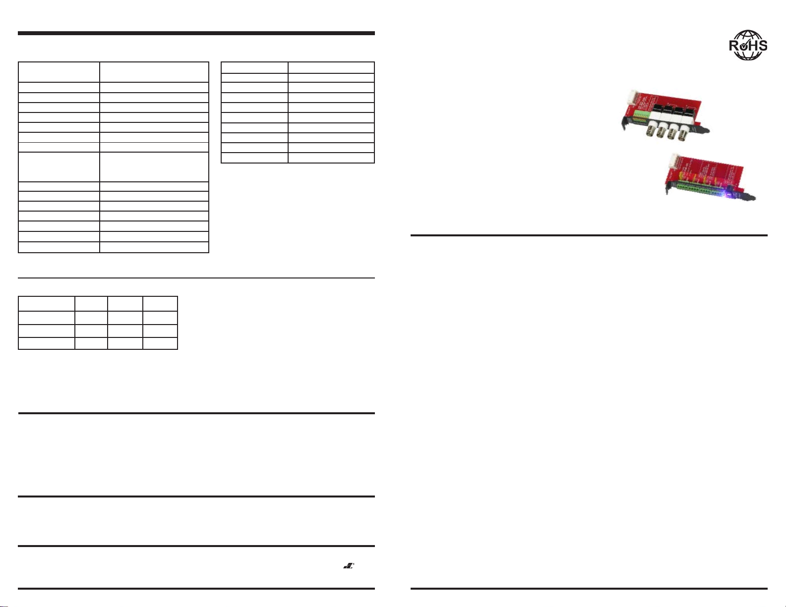
Fig. 1: EVT-PC4-VT2Q and EVT-PC4P-JTQ product overview.
Video output to DVR card
Video input
from CCTV
cameras
8-pin connector
Power Input
Jack
EVT-PC4-VT2Q
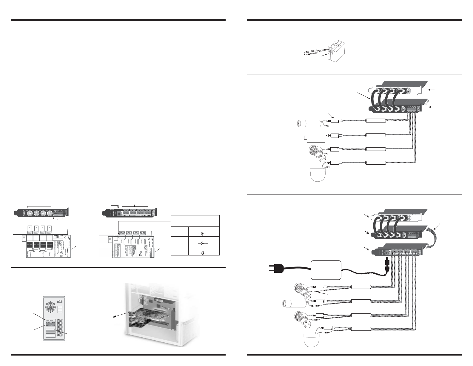
Fig. 2: Installing EVT-PC4-VT2Q and EVT-PC4P-JTQ into the back panel of PC.
1 Video-In and 1 Power-Out terminal
block per channel (Total of 4-channel)
8-pin
connector
EVT-PC4P-JTQ
Tri-Color Power LED
(12-24 VDC/VAC only)
Blue DC Polarity Correct
Red DC Polarity Incorrect
Purple AC Voltage
AC AC
~~
~~
~
~
~~
~~
Fig. 3: Wiring the EVT-PC4-VT2Q’s screwless terminal block.
Insert wire here
Figure 4: EVT-PC4-VT2Q wiring diagram.
Male-to-Male BNC cable
(included)
SECO-LARM’s EVT-PB1
(Passive Video Balun -
not included)
ENFORCER
Bullet Cam
ENFORCER
Camera
ENFORCER
Dome Cam
CAT 5
CAT 5
CAT 5
CAT 5
Figure 5: EVT-PC4-VT2Q and EVT-PC4P-JTQ wiring diagram.
NOTE: Use SECO-LARM’s EVA-F5521-3Q
pigtail connector to avoid cutting the
DC jack of the camera. Cutting it will
void the warranty.
DVR Card
EVT-PC4-VT2Q
EVT-PC4P-JTQ
12 VDC
Adapter
DVR Card
EVT-PC4-VT2Q
8-pin wire assembly
(included)
DVR card
EVT-PC4-VT2Q
(Video)
EVT-PC4P-JTQ
(Power)
Page 2
Computer
cover
Back panel slot
ENFORCER
Bullet Cam
ENFORCER
Dome Cam
CAT 5
SECO-LARM’s EVA-F5521-3Q
CAT 5
CAT 5
CAT 5
Page 3
 Loading...