

Page 1
ENFORCER Power Converters
S
o
s
D
P
P
n
D
2
@2
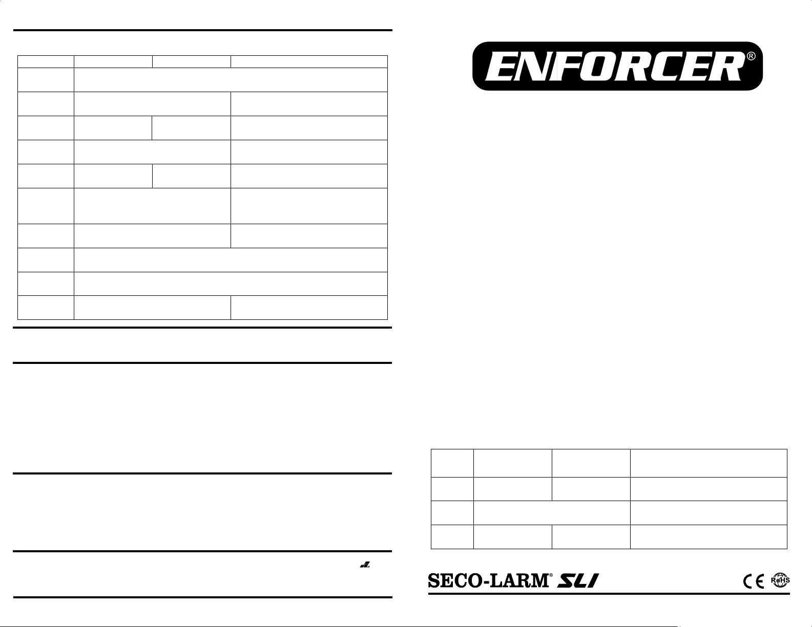
Specifications:
Model ST-LA108-TPQ ST-LA115-TPQ ST-LA130-TTQ
Input
connector
Output
connector
Input
voltage
Output
voltage
Output
current
LED
Indicators
Current
protection
Overheat
protection
Overload
protection
Dimensions
2.1mm DC Plug Terminal block
16~28 VAC/VDC 18~28 VAC/VDC
12/24 VDC
12VDC
0.8A 1.5A
Green: Power input
Built-in 3A PTC Fuse
15
1
/16”x17/16”x15/16”
(50x37x24 mm)
Terminal block
18~24 VAC/VDC for 12VDC
24~28 VAC or 26~28VDC for 24VDC
3A@12VDC
1.5A@24VDC
Green: Power input
Red: 12VDC Power output
Blue: 24VDC Power output
Built-in
Built-in
21/2”x17/8”x15/16”
(64x48x24 mm)
WARNING:
electric shock, damage the device, and void the warranty,
Incorrect installation which leads to exposure to rain or moisture inside the enclosure could cause a dangerous
WARRANTY: This SECO-LARM product is warranted against defects in material and workmanship while used in normal
service for a period of one (1) year from the date of sale to the original consumer customer. SECO-LARM’s obligation is limited
to the repair or replacement of any defective part if the unit is returned, transportation prepaid, to SECO-LARM.
This Warranty is void if damage is caused by or attributed to acts of God, physical or electrical misuse or abuse, neglect,
repair, or alteration, improper or abnormal usage, or faulty installation, or if for any other reason SECO-LARM determines that
such equipment is not operating properly as a result of causes other than defects in material and workmanship.
The sole obligation of SECO-LARM, and the purchaser’s exclusive remedy, shall be limited to replacement or repair only, at
SECO-LARM option. In no event shall SECO-LARM be liable for any special, collateral, incidental, or consequential personal
or property damages of any kind to the purchaser or anyone else.
NOTICE:
SECO-LARM policy is one of continual development and improvement. For this reason, SECO-LARM reserves the right to
change specifications without notice. SECO-LARM is also not responsible for misprints or typographical errors.
Copyright © 2014 SECO-LARM U.S.A., Inc. All rights reserved. This material may not be reproduced or copied, in whole or in
part, without the written permission of SECO-LARM.
The information and specifications printed in this manual are current at the time of publication. However, the
16842 Millikan Avenue, Irvine, CA 92606
Tel: 800-662-0800 / 949-261-2999 Fax: 949-261-7326
Website: www.seco-larm.com
E-mail: sales@seco-larm.com
Order part # 764-509%
MiST-LA1xx-TxQ_1405.docx
PITSW1
Model
Input
voltage
Output
voltage
Output
current
ST-LA108-T
ST-LA115-T
T-LA108-TPQ
16~28 VAC/VDC
0.8A
P
wer Co
In
tallation
Q
Q
ST-LA115-TPQ
18~28 VAC/VDC
12V
C
1.5A
verters
Manual
ST-LA13
ST-LA1
18~24 VAC/V
24~28 VAC or 26~
12/24
3A@1
1.5A
0-TTQ
30-TTQ
C for 12VDC
8 VDC for 24VDC
VDC
2VDC
4VDC
4 SECO-LARM U.S.A., Inc.
Page 2
ENFORCER
P
a
d
d
L
Q
o
n
s
R
e
C
o
T
a
)
n
a
s
v
r
P
e
C
s
Q
2
)
d
ST
Q
o
T
w
d
t
T
-ST
-
t
g
s
e
h
W
n
kInp
u
2(64
Q
Q
n
4
T
Q
Q
V
V
Introductio
The ENFORCE
converters, conv
useful for DC C
low-voltage DC
Features:
• Three models
• Built-in overlo
• Regulated an
• Green LED in
• Red and Blue
• ST-LA108-TP
quick installati
Dimension
ST-LA108-TPQ
Cable length (i
Overview:
-LA108-TPQ
S
With cover
Mounting
2
Front
tabs
ower Converter
:
Power Converter s
rting low-voltage A
TV cameras, acces
utput is required.
available, providing
d protection
filtered output
icates power input
EDs indicate powe
and ST-LA115-T
ns
:
n
115/16”
(50mm)
17/16”
(37mm
cluding DC plug): 4” (10
nd ST-LA115-TP
2.1mm
DC Plug
(Output)
-LA115-TP
Side
15
/16”
(24mm
Without cover
ries is a family of lo
or DC into regulate
controls, and many
arying degrees of l
output (ST-LA130-
Q Only: 2.1mm DC
mm)
Input LED
Te
rminal block
(Input)
-voltage step-down
DC outputs. Thes
other applications w
w-voltage DC outpu
TQ only)
with pigtail for
Plu
S
LA130-TT
Front
17/8”
(48mm)
LA130-TT
Wi
h cover
Output termi
block (blac
SECO
power
converters are
ere regulated
imple and
1
/2”
mm)
ithout cover
al
)
Output
LED
ut terminal block
(bl
e, non-polarized)
-LARM U.S.A., I
Side
15
/16”
(24mm)
Potentiometer
Mini jum
Input
LED
per
c.
ENFORCER Power Converters
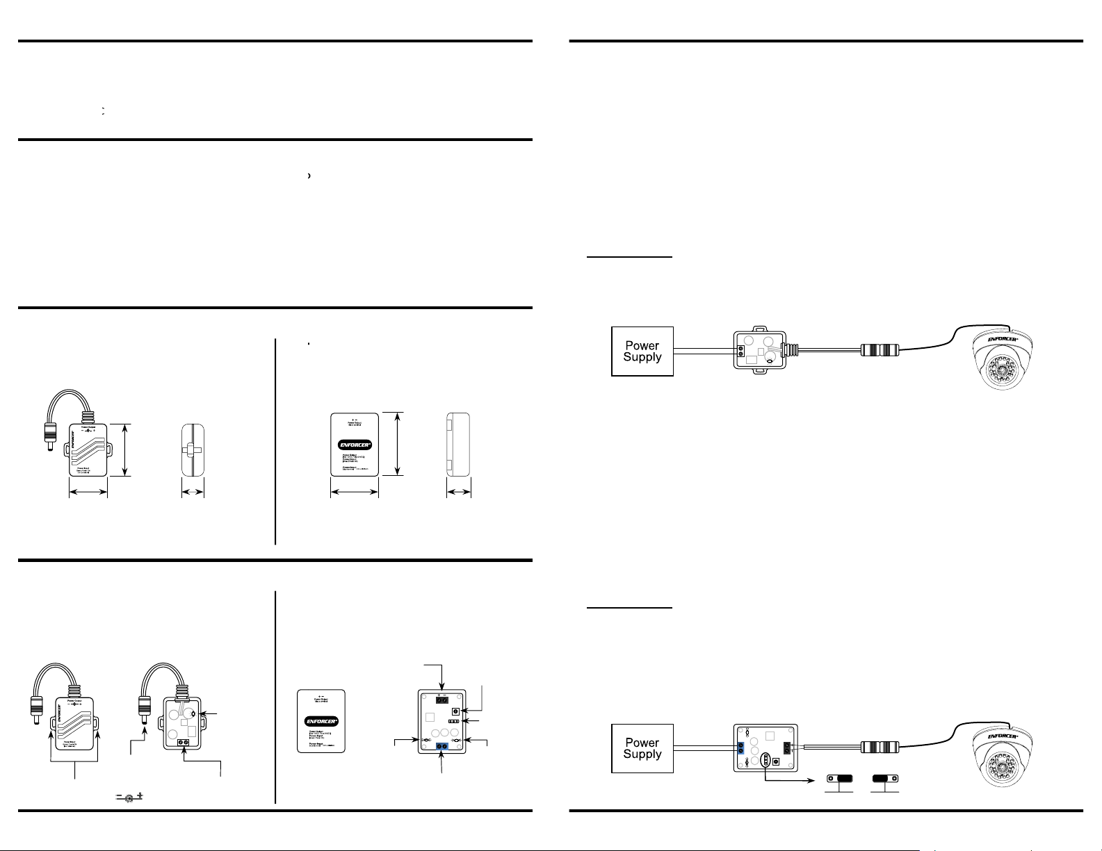
Installation
-LA108-TPQ and ST-LA115-TP
S
1. Remove the cover by simultaneously pressing the two indented slots located on both sides
of the unit.
2. Connect power to the input side terminal block. Polarity is not important.
− For the ST-LA108-TPQ, connect a 16~24 VAC/VDC power supply.
− For the ST-LA115-TPQ, connect an 18~24 VAC/VDC power supply.
Note: Do not turn on the power supply until ready to test.
Note: Use between 16AWG and 22AWG wire for the input.
3. Turn the power supply on. The power converter’s green LED should turn on to indicate
input power.
4. Test the output.
sure it is correct.
5. Connect the device requiring power to the DC plug.
6. Test the device to ensure proper operation.
7. Replace the plastic cover on the voltage converter and secure it in the desired location.
Use a voltage meter to measure the output from the DC plug to make
ST-LA130-TT
1. Remove the cover by removing the screws on the back of the unit with a screwdriver
(not included).
2. Set the desired voltage output via the on-board mini jumper, see illustration below.
3. Connect the power supply to the blue input terminal block. Polarity is not important.
− For 12VDC output, connect an 18~24 VAC/VDC power supply.
− For 24VDC output, connect a 24~28 VAC or 26~28 VDC power supply.
Note: Do not turn on the power supply until ready to test.
Note: Use between 16AWG and 22AWG wire for the input.
4. Turn the power supply on. The ST-LA130-TTQ’s green LED should turn on to indicate input
power. The red LED should light to indicate 12VDC power output while the blue LED should light
to indicate 24VDC power output.
5. Test the output.
block to make sure it is correct.
Note: The output voltage can be adjusted by about 10% by turning the on-board potentiometer.
Turn clockwise to increase the voltage, turn counterclockwise to decrease the voltage.
Range: 12~13.3 VDC at 12VDC output, 24~26.8 VDC at 24VDC output.
6. Connect the device requiring power to the black output terminal block. Observe correct polarity.
7. Test the device to ensure proper operation.
8. Replace the plastic cover on the voltage converter and secure it in the desired location.
Use a voltage meter to measure the output from the black output terminal
12VDC or 24VDC
24V 12
Mini jumper voltage selector
24V 12
SECO-LARM U.S.A., Inc. 3
 Loading...