

Page 1
NOTE: Products with model numbers that end with “Q” or have a round green “Q” sticker are RoHS compliant.
Selectable input 12/24VDC
Adjustable voltage cut-off and restore point
Master ON/OFF switch
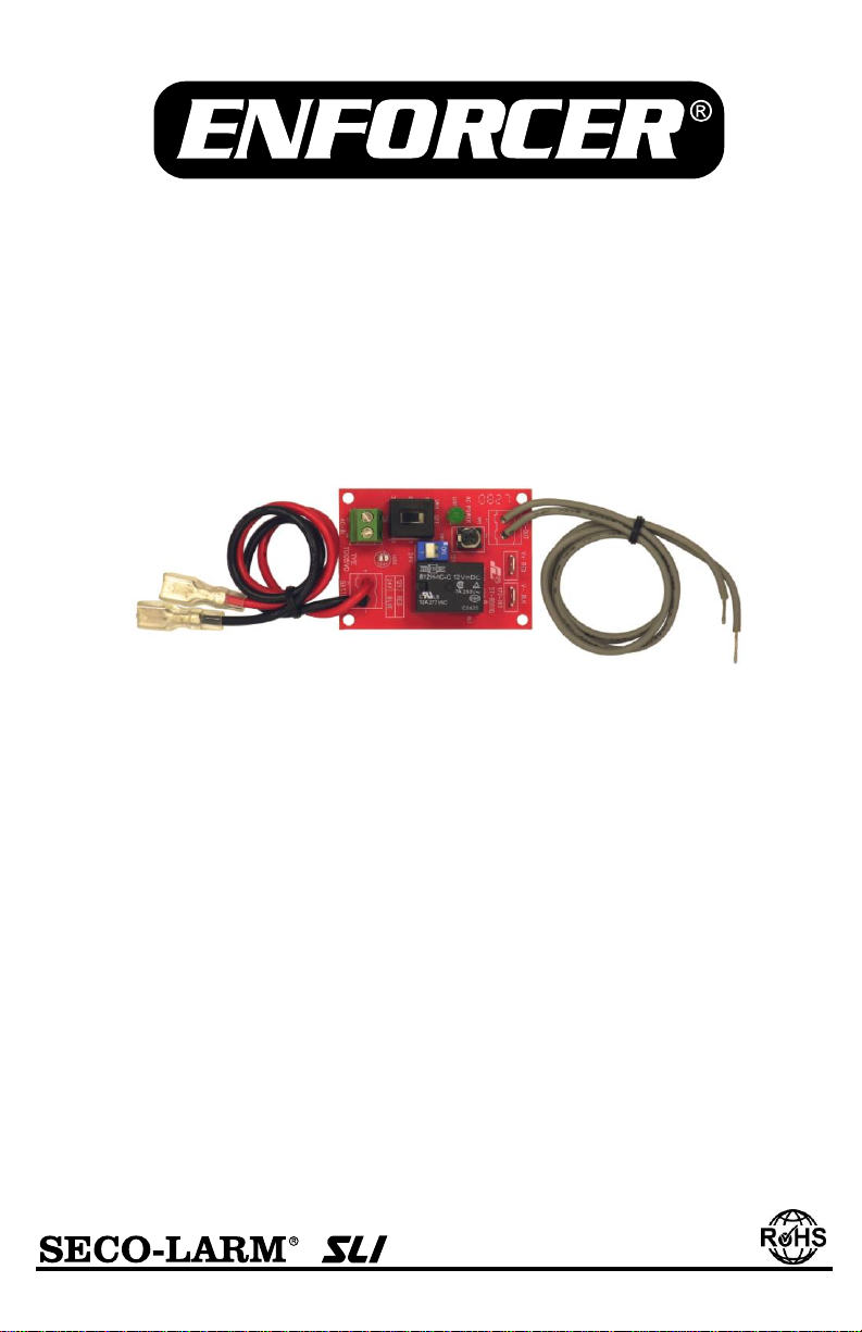
The ENFORCER ST-BD01Q Low-Voltage Battery Cut-Off prevents the deep discharge
of the backup batteries. The ST-BD01Q ties directly into most 12 or 24 VDC power
supplies or alarm panels for easy plug-and-play installation. A Master ON/OFF switch
easily connects or disconnects the battery and AC power supply from the control panel.
Green LED AC power indicator
Dual-color DC LED indicator
Includes double-sided tape
Manual
ST-BD01Q
Low-Voltage Battery Cut-Off
Page 2
ENFORCER LOW-VOLTAGE BATTERY CUT-OFF
Overview:
Relay contact rating
7Amp@30VDC
LED
indicators
AC
Green
DC
Red: 12VDC
Blue: 24VDC
Connections
AC input
Terminal block
AC output
Gray wire leads
DC
Quick-connect terminal (battery side)
On-board male spade terminal*
Dimensions
23/8” x 13/4” x 7/8” ( 60 x 45 x 22 mm)
*Must connect for proper operation.
IMPORTANT: The polarity on all wiring connections MUST be
connected properly; incorrect polarity connection will damage the
unit. When using 24VDC the voltage selector switch MUST be set
at 24VDC, incorrectly setting the unit may cause damage.
Specifications:
For operating voltages please see Table 1 on Page 3.
Installation:
1. Disconnect the AC power and back-up battery from the control panel or power supply.
2. Turn the master switch of the ST-BD01Q OFF (factory default is OFF).
3. Select the correct voltage setting (12 or 24 VDC) via the 12/24 VDC selector switch (factory
default is 12VDC).
4. If necessary, connect the low voltage AC to the AC input terminal block.
5. Connect the AC output gray wires from the ST-BD01Q to the AC input of the control panel or
power supply.
6. Connect the male spade terminals of the ST-BD01Q to the DC output terminals of the control
panel or power supply.
Must connect for proper operation.
7. Connect the female spade lugs of the battery wires to the back-up battery.
Observe correct polarity.
8. Use the included double sided tape and secure the ST-BD01Q module on the desired location.
9. Double check all connections before turning the master switch ON.
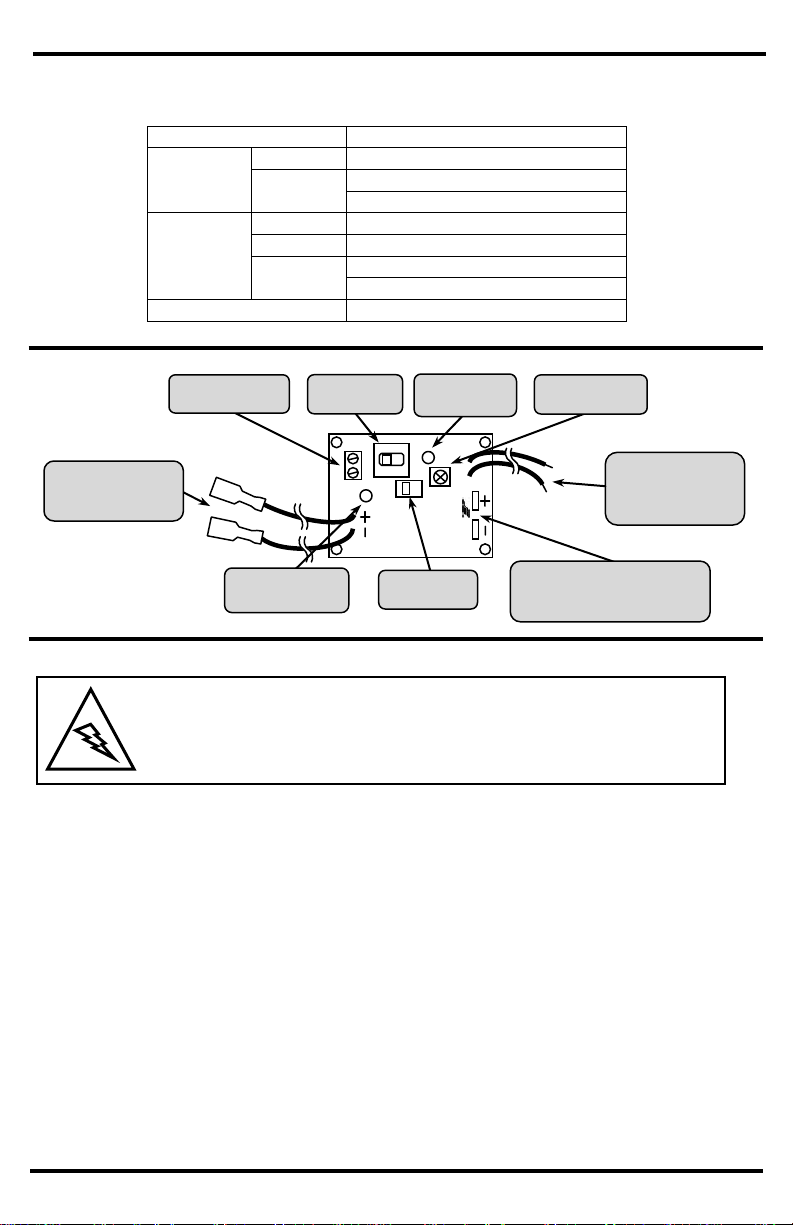
ST-BD01Q
1
2
1
2
AC input
(green terminal block)
AC Output to
AC input of control
panel or power supply
(9” gray wires)
12/24 VDC
selector switch
Master
ON/OFF switch
Green LED AC
power indicator
DC connector
male spade terminal connects to
control panel or power supply
Dual-color DC
power indicator LED
Adjustable voltage
cut-off knob
Battery wires to
back-up battery
(10” red and black wires)
2 SECO-LARM U.S.A., Inc.
Page 3

ENFORCER LOW-VOLTAGE BATTERY CUT-OFF
Green LED
Off, AC power not present
On, AC power present
Dual-color
LED
Off, DC power not present
Red, 12VDC present
Blue, 24 VDC present
Sample Application #1: Connecting to a 12VDC Power Supply
or Control Panel
Sample Application #2: Connecting to a 24 VDC Power Supply
or Control Panel
1. The ST-BD01Q turns off both AC and DC power to the control panel or power supply.
2. The green LED indicates AC power is present.
3. The dual-colored LED indicates DC power is present and if it is 12 or 24VDC (see Table 2).
Master ON/OFF Switch:
1. The ST-BD01Q’s voltage cut-off point is preset at approximately 9.6VDC when set at 12VDC
setting and about 19.6VDC when set at 24VDC setting.
2. To adjust the voltage cut-off point, carefully turn the adjustable voltage cut-off knob clockwise
to increase and counter-clockwise to decrease. See the Table 1 below for the adjustable
voltage cut-off range.
Table 1: Operating Voltage
12VDC
24VDC
DC operating
voltage
10~14 VDC
22~28 VDC
AC input
12~18 VAC
24~30 VAC
Adjustable
cut-off range
9~10 VDC
19.2~20.3 VDC
Table 2: LED Indicators
Operation:
Voltage Cut-Off:
ST-BD01Q
Control
Panel
ST-UVDA-W180Q
Open-frame
Transformer
Two 12VDC Backup
batteries in series
ST-BD01Q
AC Input
Battery
ST-BD01Q
1
2
1
2
Set at 24VDC
AC Output
24 VDC
ST-2406-5A
Power supply / charger
or control panel
12VDC Backup
battery
ST-BD01Q
Set at 12VDC
ST-UV16-W100Q
Open-frame
Transformer
AC Input
Battery
AC Output
12VDC
1
2
1
2
SECO-LARM U.S.A., Inc 3 SECO-LARM U.S.A., Inc. 33 3
Page 4

ENFORCER LOW-VOLTAGE BATTERY CUT-OFF
WARRANTY This SECO-LARM product is warranted against defects in material and workmanship while used in normal
service for a period of one (1) year from the date of sale to the original consumer customer. SECO-LARM’s obligation is
limited to the repair or replacement of any defective part if the unit is returned, transportation prepaid, to SECO-LARM.
This Warranty is void if damage is caused by or attributed to acts of God, physical or electrical misuse or abuse, neglect,
repair, or alteration, improper or abnormal usage, or faulty installation, or if for any other reason SECO-LARM determines
that such equipment is not operating properly as a result of causes other than defects in material and workmanship.
The sole obligation of SECO-LARM, and the purchaser’s exclusive remedy, shall be limited to replacement or repair only,
at SECO-LARM’s option. In no event shall SECO-LARM be liable for any special, collateral, incidental, or consequential
personal or property damages of any kind to the purchaser or anyone else.
NOTICE: The information and specifications printed in this manual are current at the time of publication. However, the
SECO-LARM policy is one of continual development and improvement. For this reason, SECO-LARM reserves the right
to change specifications without notice. SECO-LARM is also not responsible for misprints or typographical errors.
Copyright © 2012 SECO-LARM U.S.A., Inc. All rights reserved. This material may not be reproduced or copied, in
whole or in part, without the written permission of SECO-LARM.
SECO-LARM
®
U.S.A., Inc.
16842 Millikan Avenue, Irvine, CA 92606 Website: www.seco-larm.com
Tel: 800-662-0800 / 949-261-2999 Fax: 949-261-7326 E-mail: sales@seco-larm.com
Switching Power Supply
Series
Power Supply / Charger
Series
Programmable Timer
Series
Open-Frame Transformers
Voltage Boosters
ST-LA110-TTQ
(shown)
ST-2406-7A
(shown)
SA-025Q
(shown)
ST-HB105-TTQ
(shown)
ST-UV28-T350Q
(shown)
ST-UV12-S3.0Q
(shown)
Voltage Converter
Series
Power indicator LED not lit
Check to make sure AC power is on
Check AC power input and output connections
Check the main switch if it is on
Voltage selector switch set at 12VDC but
dual-color DC LED is blue
Voltage selector switch set at wrong setting
Voltage selector switch set at 24VDC but
dual-color DC LED is red
No voltage present on DC connector
(male spade terminals)
Dual-color DC LED is off
Must have initial voltage from DC power supply or
Control Panel at DC connector to activate latching relay
MiST-BD01Q_1112.docx
Troubleshooting:
Also Available from SECO-LARM:
PITSW1
Order Part# 763-163-2%
4 SECO-LARM U.S.A., Inc.
 Loading...