

Page 1
®
Features:
Mechanical Keypad Door Lock
SD-962H-8LAQ
Manual
Non-handed installation
External and internal entry lever
13 code buttons, over 8,000 possible codes
Lock code easily changed
Suitable for door thicknesses from
13/16"~21/8" (30~54 mm)
Tubular latchbolt included
Heavy-duty steel case US32D/630
Fully mechanical
No batteries or other power source required
Free egress from inside
Simple Installation
Page 2
SECO-LARM Mechanical Keypad Door Lock
The
SECO
-
LARM
Mechanical Keypad Door Lock provides secure locking while avoiding the
letters/digits can be entered in any order. Since it is completely mechanical, there is no need to run
Specifications:
Overview:
Introduction:
1x Exterior handle assembly
4x Code tumblers
4x Wood screws
1x Interior handle assembly
1x
Latchbolt support post
2x
Machine screws (36mm)
1x Strike plate
2x
Hexagonal mounting posts
2x
Machine screws (48mm)
1x Strike dust box
3x
Spindles (75, 85, 100 mm)
2x
Neoprene door seals
1x Latchbolt
1x
Code card
1x
Tweezers
1x Hex wrench
1x
Manual
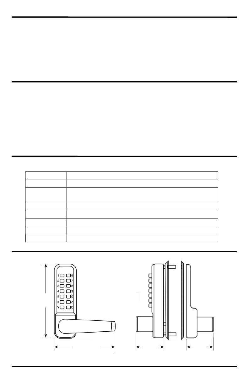
43/4" (120mm)
hassle and cost of dealing with providing, duplicating, or replacing keys. Unlike keyed locks, the
lock code can be easily changed by the user at any time. The code is not sequential, so the code
wires from a power supply or replace batteries. The inside handle always operates to allow safe
egress in an emergency.
Parts List:
(with buttons)
(2 red, 2 blue)
(2 for latchbolt, 2 for plate)
Type Fully mechanical keypad lock
Code length 4~6 Digits (0~9, X, Y, and Z)
Handed
Bolt throw
Backset 23/4" (70mm)
Housing Heavy-duty satin finish stainless steel US32D/630
Dimensions 2" x 43/4" x 51/2" (50x120x140 mm)
Weight 3-lb 1-oz (1.35kg)
(factory default – internal, right-handed / external, left-handed)
Field reversible
1
/2" (13mm)
51/2"
(140mm)
2"
(50mm)
2"
(50mm)
2 SECO-LARM U.S.A., Inc.
Page 3
SECO-LARM Mechanical Keypad Door Lock
The Lock Code:
Each lock assembly is given a random code at the factory
Blue
Red
Square
Square
Never remove the
plate
Square
Keypad
and that code is printed on a card shipped with the lock. The
Fig. 1
code can be easily changed as shown below.
NOTES:
A. When changing the lock code, it is crucial that you
Lock code
press and hold the "C" button throughout the duration
of the code changing process. Failure to do so will
damage the lock code module.
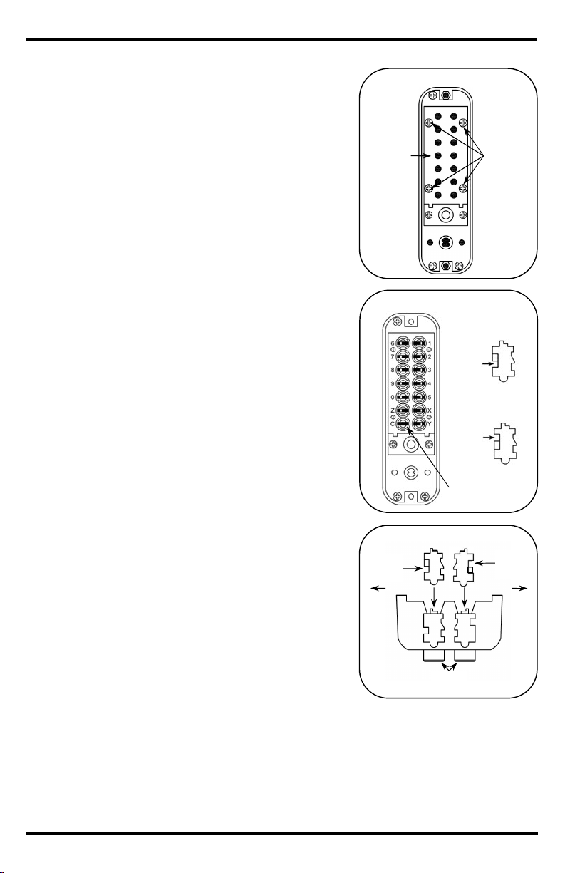
B. Never remove the tumbler from the "C" position (Fig. 2).
C. Take care to insert the lock code tumblers properly. The
red or blue marks on the code tumblers should all be in
line if the code tumblers are inserted correctly.
D. Place a drop cloth on a good, flat surface to help
Fig. 2
prevent screws and code tumblers from accidentally
bouncing off the table and getting lost.
E. The lock code is not sequential. In other words, if the
cut
lock code numbers are 135Y, any sequence (Y135,
513Y, 3Y51, etc.) will unlock the door
IMPORTANT: Failure to adhere to the above could result in
a damaged lock code module or lost parts.
Changing the Lock Code
1. From the back of exterior assembly, remove the 4 RED
cut
tumbler from this
"C" position.
lock code plate retaining screws (see Figs. 1 and 2).
2. The factory setting uses 5 RED active lock code
Fig. 3
tumblers, 8 BLUE inactive lock code tumblers, and 1
code clearing tumbler in the "C" position.
IMPORTANT: Never remove the code clearing tumbler
cut
Outside
Outside
from the "C" position.
3. Determine the desired lock code and write it down to
avoid any mistake. Use that to determine which code
tumblers must be replaced. Red code tumblers
represent the code and blue code tumblers represent
buttons
the numbers/digits that are not part of the code.
4. While pressing the “C” button, use the provided tweezers to remove one or more code
tumblers as needed for the desired lock code (the numbers for each button are etched into
the housing next to its corresponding code tumbler, see Fig. 2).
5. While continuing to hold the "C" button down, insert the appropriate colored code tumbler(s)
as needed. Ensure that each code tumbler is inserted such that the side with one square cut
is facing the outside of the housing (see Fig. 3).
SECO-LARM U.S.A., Inc. 3
Red lock
code plate
screws
tumbler
tumbler
Square
cut
Page 4

SECO-LARM Mechanical Keypad Door Lock
Determine Door Swing and Handedness:
Prepare the Door and Install the Latchbolt:
Setting the Lock Code (Continued):
Fold the template on the dotted line and place it on the door
D
etermine whet
her the door is right
- or
When facing the door from the outside, if the hinge
Replace
the lock code plate and
secure
it
with the 4 RED screws.
button followed
Use chisel
to form holes
Latch
center
line
(3mm)
6.
7. Check the code to ensure accuracy before installing. First press the "C" (Clear)
by the chosen code and move the handle on the keypad assembly to test the lock.
IMPORTANT NOTES:
A. Spare code tumblers are provided to increase the number of code digits if needed.
B. Carefully note each code tumbler's orientation as it is inserted into the lock code assembly.
The square cut should be oriented toward the outside of the housing.
C. Do not leave any code tumbler position empty.
D. Store the manual, actual code, and unused code tumblers in a safe place.
left-handed.
is on your right, then the door is right-handed. If
the hinge is on your left, the door is left-handed
Fig. 4
Right-handed
Inside
Left-handed
Outside
(see Fig. 4).
1.
so that the line marked "Latch center line" is aligned with the
Fig. 5
latch strike plate's center line when the door is closed. Use
tape to hold the template temporarily in place (see Fig. 5).
2. Drill the six
3. Viewing the door from the latch edge, mark the horizontal
3
/8" (10mm) holes as shown on template.
center point on the "Latch center line" and drill a 1" (25mm)
hole to a depth of 33/4" (95mm).
4. Use a chisel to form the 4 horizontally-aligned
3
/8" (10mm)
into a slot
holes into a single slot.
5. Insert the latch into the latch hole and mark around the
faceplate to determine the size of the recessed area needed
to allow the faceplate to be flush with the door.
6. After marking around the faceplate, remove the latch and
Fig. 6
Cut a
1
deep hole
use a chisel to cut a 1/8" (3mm) deep hole as marked. This
will ensure that the faceplate fits flush with the door (Fig. 6).
7. Insert the latch assembly, ensuring that curved part of the
latchbolt is correctly oriented for the door's swing. Secure
the latch assembly with 2 wood screws provided.
4 SECO-LARM U.S.A., Inc.
/8"
Page 5

SECO-LARM Mechanical Keypad Door Lock
Prepare the Lock for Mounting:
Prepare the Door and Install the Latchbolt (Continued):
Changing the Interior Latchbolt Handedness (for left
-
handed doors)
Positioning the Spindles
8. Choose the correct spindle that best matches the door's thickness.
Fig. 7
For doors less than 17/16" (37mm), use the shorter spindle 215/16"
(75mm). For doors 17/16"~115/16" (37~50mm) use the 33/8" (85mm)
spindle. For thicker doors, use the 315/16"(100mm) spindle.
9. Position the spindle in the center, through the latch hub (Fig. 7)
according to the door's handing as shown in Figs. 8 and 9.
Fig. 8
Spindle orientation for right-handed door
(viewed from outside)
Fig. 9
Spindle orientation for left-handed door
Latch hub
(viewed from outside)
NOTES:
A. The interior lock assembly is set for right-handed doors from the factory. You should only
need to set the handedness of this unit if your door is left-handed.
B. The exterior lock assembly is already set for left-handed doors from the factory.
Interior Lock Assembly
1. Hold the interior handle assembly as it would be oriented for the handedness and swing of the
door to determine the correct handle orientation.
2. Loosen the set screw (see Fig. 10) and rotate the handle to its correct horizontal position if
necessary (see Fig. 11). Tighten the set screw to maintain handle position.
3. Check that the lever handle now turns in a clockwise direction and returns freely.
4. Viewing the interior handle assembly from the back, note the blue handing screw's location—
right side for left-handed and left side for right-handed doors (see Fig. 11).
5. If necessary, remove and change the location of the blue screw depending on the orientation
of the interior handle.
Fig. 10
Set screw
Fig. 11
Left handed
Blue handing
screw
Right handed
SECO-LARM U.S.A., Inc. 5
Page 6

SECO-LARM Mechanical Keypad Door Lock
Mount the Lock:
Prepare the Lock for Mounting (Continued):
Select the appropriate screws depending on
handed doors, the
Outside
Inside
Neoprene seals
Exterior Handle Assembly
The handedness of the external handle assembly (default,
left-handed) will be set after installation.
Installing the Latchbolt Support Post
From the back of the exterior handle assembly, fit the latchbolt
support post in the correct position. For rightsupport post should be fitted on the left. For left-handed doors,
the support post should be fitted on the right (Fig. 12 and 13).
Fig. 12
Right-handed
Fig. 13
Left-handed
1.
Fig. 14
the door's thickness. For doors less than 17/8"
(48mm), use the shorter 17/16 (36mm) screws.
2. Fit the neoprene seals to both the exterior and
the interior handle assemblies (see Fig. 14).
3. Screw the two hexagonal mounting posts in
place to the exterior handle assembly (Fig. 14).
4. Hold the exterior handle assembly onto the
door with the spindle in place and ensure that
the latchbolt support post engages the hole in
the latchbolt assembly.
5. Hold the interior handle assembly in place on
the inside of the door so that the spindle is
properly set in the handle interior handle
assembly hub.
6. Screw both sides together using the machine
In-swing, left-handed door installation shown
Fig. 15
Hexagonal
mounting posts
Rotate
screws on the top and bottom.
7. Before final tightening of screws, make sure
the door lock is vertical. Test to make sure the
lock functions correctly and moves easily.
NOTE: DO NOT over-tighten the machine screws as this can lead to poor operation or damage
the lock assembly.
8. For right-handed doors, change the exterior lever handing at this time.
a. To prevent damage from forced entry the external handle is fitted with a clutch.
b. To change the handle's orientation, simply apply force to rotate the handle to its proper
handing (see Fig. 15).
9. Check that the set code is able to unlock the door before closing it to avoid being locked out.
6 SECO-LARM U.S.A., Inc.
Page 7

SECO-LARM Mechanical Keypad Door Lock
Install the Strike Plate:
Frame
Door
Frame
Door
User Operation:
Latchbolt
/16" (1
mm)
deep
deep
Partially close the door and mark where the
To unlock the door:
each key in the lock code in any order. The lock code is not sequential and therefore the
1.
latchbolt contacts the door frame.
2. Close the door. With the door in a closed
position, measure the distance from the
door latch to the edge of the door frame.
This is the door latch line. This is shown as
“X” in Figs. 16 and 17.
3. Open the door and mark the door latch line
on the frame.
4. Using the strike plate as a template, mark
the outer edges of the strike plate, the inner
hole and the screw holes.
5. Using a chisel, cut a
recess for mounting the strike plate so that it
1
/16" (1mm) deep
fits flush with the frame. (Fig. 18.)
6. Use the strike dust box as a template to
mark, drill, and chisel out the latchbolt hole
to a depth of at least 1/2" (13mm) to
accommodate the strike dust box (Fig. 18,
dotted lines).
7. Insert the strike dust box into place along
with the strike plate. Secure both with the
provided wood screws.
8. Test that the door closes easily and that
latchbolt fits securely into the strike plate
aperture. Ensure that that the deadlatch
(Fig. 19) does not enter the strike plate
aperture. If it does, loosen and reposition
the strike plate as necessary.
Fig. 16
Fig. 17
Fig. 18
Strike
plate
Fig. 19
X
X
Door latch
line
X
X
Door latch
line
1
1/2" (13mm)
Strike
dust box
Deadlatch
1. Press the "C" (clear) key to make sure that no keys are already pressed or partially pressed.
2. Press
keys can be pressed in any order. For example, if the lock code numbers are 135Y, any
combination of these numbers (Y135, 513Y, 3Y51, etc.) will unlock the door.
3. Turn the lever to open the door.
In case of an error or if the door doesn't unlock, press the "C" (clear) key and press the keys in the
lock code again.
SECO-LARM U.S.A., Inc. 7
Page 8

SECO-LARM Mechanical Keypad Door Lock
Troubleshooting:
16842 Millikan Avenue, Irvine, CA 92606
Website:
www.seco
-
larm.c
om
Phone: (949) 261
-
2999 | (800) 662
-
0800 Email: sales@seco
-
larm.com
PITSW9
MI_SD-962H-8LAQ_181224.docx
NOTICE
:
The SECO
-
LARM policy is one of continual development and improvement. For that reason, SECO
-
LARM
rademarks
Inc. All
LIMITED LIFETIME
WARRANTY:
This SECO
-
LARM product is warranted against defects in material and workmanship
LARM’s obligation is limited to the repair or replacement of any defective part if the unit is returned,
is caused by or attributed to acts of God, physical
ny
erly as a result of causes other than
and the purchaser’s exclusive remedy, shall be
le for any special,
For
IMPORTANT
:
that the installation and configuration of
Door Closers
Surface Mount
Recessed
-
Mount
Miniature Single
SD-C121-S shown
SM-
S200Q/W shown
SM-
207-5Q/BR shown
E-
964-S50TB shown
The code doesn't unlock the door.
The latch lever turns, but the latchbolt
does not retract
Also Available from
Magnetic Contacts
Press the "C" (clear) key and enter the passcode again.
Ensure that each key (including the "C" key) has been fully
pressed.
Remove the lock and the lock code plate to ensure that each
letter/digit in the chosen code is represented by a red code
tumbler and all other code tumblers are blue.
Remove and reinsert the code tumblers, ensuring that they are
correctly oriented and fully inserted.
The spindle used is too short for the door's thickness. The
spindle must be long enough to simultaneously engage both
the interior and exterior levers. Use a longer spindle.
®
:
Magnetic Contacts
Photobeam Sensors
this product complies with all national, state, and local laws and codes related to locking and egress devices. SECO-LARM
will not be held responsible for the use of this product in violation of any current laws or codes.
while used in normal service for the lifetime of the product (one (1) year from the date of sale to the original customer for
the finish). SECOtransportation prepaid, to SECO-LARM. This Warranty is void if damage
or electrical misuse or abuse, neglect, repair or alteration, improper or abnormal usage, or faulty installation, or if for a
other reason SECO-LARM determines that such equipment is not operating prop
defects in material and workmanship. The sole obligation of SECO-LARM
limited to the replacement or repair only, at SECO-LARM’s option. In no event shall SECO-LARM be liab
collateral, incidental, or consequential personal or property damage of any kind to the purchaser or anyone else.
products sold in countries other than the US, the warranty is 1 (one) year from the date of sale to the original customer.
reserves the right to change specifications without notice. SECO-LARM is also not responsible for misprints. All t
are the property of SECO-LARM U.S.A., Inc. or their respective owners. Copyright © 2018 SECO-LARM U.S.A.,
rights reserved.
Users and installers of this product are responsible for ensuring
®
U.S.A., Inc.
8 SECO-LARM U.S.A., Inc.
 Loading...