

Page 1
Installation Manual
Manual de instalación
Mode d’emploi
SD-7623-GSTQ
SD-7223GW-LQ
Includes English, Spanish, and French plates.
Incluye placas de inglés, español, y francés.
Comprend plaques en anglais, espagnol et français.
English ...................................... 2
Français .................................... 8
Warranty/Garantía/Garantie .. 12
Español ..................................... 5
Also Available ........................ 11
SD-7202GC-PEQ / SD-7202GC-PTQ / SD-7223GW-LQ / SD-7623-GSTQ
SD-7202GC-PEQ
SD-7202GC-PTQ
Page 2
ENFORCER Pushbutton Request-to-Exit Plates
PUSH
Figure 3
Specifications:
Models:
1x
Request-to-exit plate
2x
Wallplate screws
5x
5x
2x
2x
Colored leads:
(SD-7202GC-PEQ)
(SD-7223GW-LQ)
(SD-7202GC-PTQ)
(SD-7623-GSTQ)
1x
Installation manual
1x
Spare LED bulb
1x
Resistor for 24VDC
(SD-7623-GSTQ only)
2x
Replacement message plates
(Spanish, French)
Parts List:
SD-7202GC-PEQ
Large illuminated “PUSH TO EXIT” button
Language easily changed to Spanish or French
Colored 12-inch wire leads with easy-to-attach
spade lugs for fast installation
LEDs Give over 50,000 hours of illumination
Includes stainless-steel single-gang plate
(except SD-7223GW-LQ, which is white plastic)
SD-7223GW-LQ
SD-7202GC-PTQ
SD-7623-GSTQ
Same as SD-7202GC-PEQ, but
with white plastic faceplate
Same as SD-7202GC-PEQ, but
with additional timer (1~180 sec)
and buzzer output
Same as SD-7202GC-PTQ, but
with additional customizable LED
status indicator
Note: This should be done before connecting
any wires.
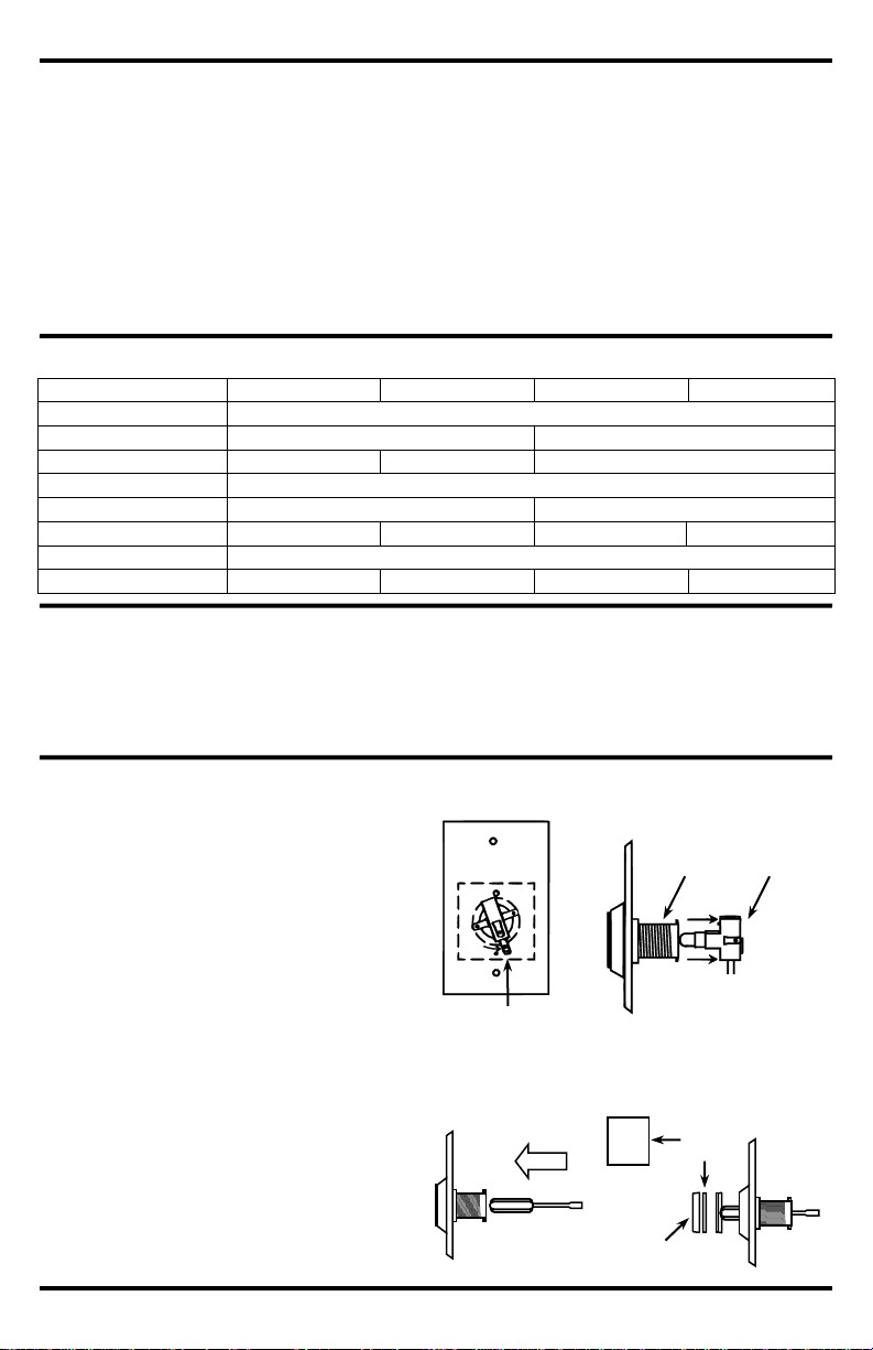
1. Carefully twist the switch and bulb assembly
counterclockwise about 20° (see Fig.1), and
then pull it out of the black tube (see Fig. 2).
2. Insert the blunt end of a small tool or rod (e.g., a
screwdriver or pen, ~3/8” (10mm) diameter) into
the black tube (see Fig. 3). It should slide in
easily all the way until it contacts the inside of
the front lens/message plate assembly. Push
the lens/message plate assembly with your tool
until it pops off (see Fig. 4). Be careful not to
lose the spring.
3. Take off the transparent green lens and insert
the desired message plate.
4. Check that message plate orientation is correct.
5. Snap the lens assembly back on and replace
the switch/bulb assembly.
Changing the Message Plate:
Model
SD-7202GC-PEQ
SD-7223GW-LQ
SD-7202GC-PTQ
SD-7623-GSTQ
Operating voltage
12 or 24VDC
Current rating
10A@250VAC
3A@24VDC
Faceplate
Brushed stainless
White plastic
Brushed stainless
Operating temperature
-40°~167° F (-40°~75° C)
Built-in timer
No
Yes
LED status indicator
No
No
No
Yes
Dimensions
4½”x2¾” (11.4x7.6 cm)
Weight
3.7-oz (105g)
2.2-oz (62g)
4.7-oz (133g)
5.1-oz (144g)
Switch and
bulb assembly
Threaded
housing
Figure 2
Figure 1
Switch and
bulb assembly
Figure 4
Figure 3
Message
Plate
PUSH
TO
EXIT
Transparent
green lens
2 SECO-LARM U.S.A., Inc.
Page 3
ENFORCER Pushbutton Request-to-Exit Plates
Wiring the SD-7202GC-PTQ (with timer module):
Wiring the SD-7202GC-PEQ and SD-7223GW-LQ:
1. Run four wires through the wall to a single-gang back-box
as follows:
a. Two wires from a 12VDC or 24VDC power source for
the pushbutton light.
b. One wire from either the NO or NC terminal of a device
such as an alarm or access control system which can
unlock an electrically-controlled lock.
c. One wire from the COM terminal of that device.
2. Connect the included colored wires to the switch
(see Fig. 5):
a. To power the pushbutton’s LED, connect 1 GREEN wire to each of the brass-colored spade
connectors on the sides of the black switch.
b. Connect GREEN/WHITE wire to the N.C. connector on the black switch (if needed).
c. Connect BLUE/WHITE wire to the N.O. connector on the black switch (if needed).
d. Connect WHITE wire to the COM connector on the black switch.
3. Connect the colored wires to wires from the alarm or access control system and the light’s power
source (see Fig. 5):
a. 2x GREEN wires – To a 12 or 24 VDC source. The polarity of the LED must be observed.
b. GREEN/WHITE wire – To the N.C. terminal of the alarm or access control system (if needed).
c. BLUE/WHITE wire – To the N.O. terminal of the alarm or access control system (if needed).
d. WHITE wire – To the COM terminal of the alarm or access control system.
4. Screw the plate onto the back-box, taking care not to crimp the wires.
IMPORTANT
Users and installers of this product are responsible for ensuring that the installation and configuration of this
product complies with all national, state, and local laws and codes related to locking and egress devices.
SECO-LARM will not be held responsible for the use of this product in violation of any current laws or codes.
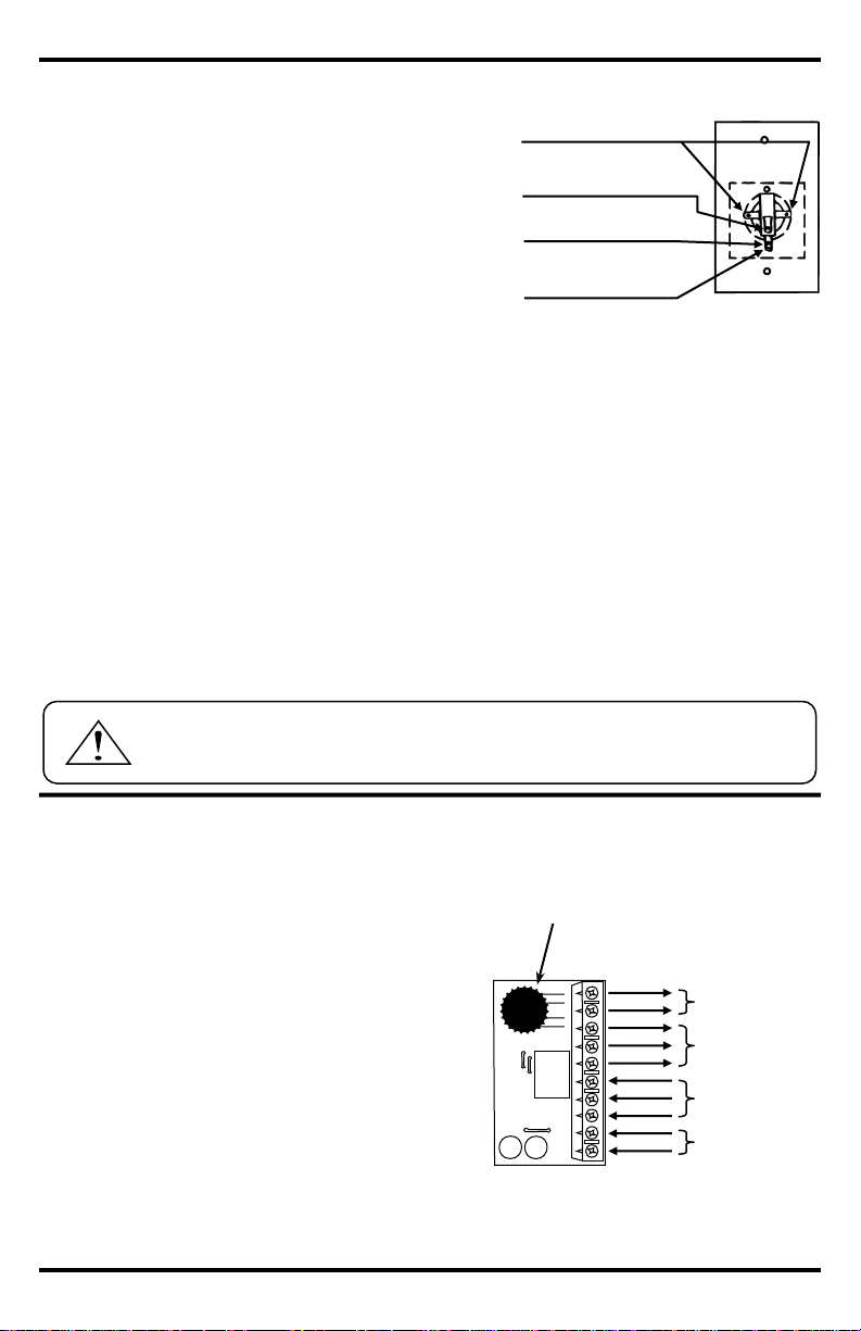
Figure 5
Buzzer
Output
Relay Output
(3A@24VDC)
Trigger Input
(Factory prewired)
Power Input 12 or 24
VDC (non-polarized)
(N.O.)
(N.C.)
(COM)
(COM)
(N.O.)
(N.C.)
(+)
(–)
Note: Terminal legend can be found on back of PCB.
To adjust time (1~180 sec), turn
trimpot clockwise to increase,
counterclockwise to decrease.
Timer
Adjustment
Trimpot
Figure 6
1. To power the pushbutton’s LED, connect 1 GREEN
wire to each of the brass-colored spade connectors on
the sides of the black switch and bulb assembly (see
Fig. 5 above) and connect the other side of each
GREEN wire to a 12 or 24 VDC source. The polarity of
the LED must be observed.
2. Connect 12 or 24 VDC (non-polarized) to the power input
terminals of the timer module (see Fig. 6).
3. Connect an N.O. or N.C. device, such as an
electromagnetic lock or alarm, to the relay output
terminal block as desired (3A@24VDC max.).
4. Connect buzzer to the buzzer output terminal if desired.
5. Set the time of the timer module between 1~180 sec via
the trimpot. Turn clockwise to increase and
counterclockwise to decrease. Test to ensure the timer
is set correctly.
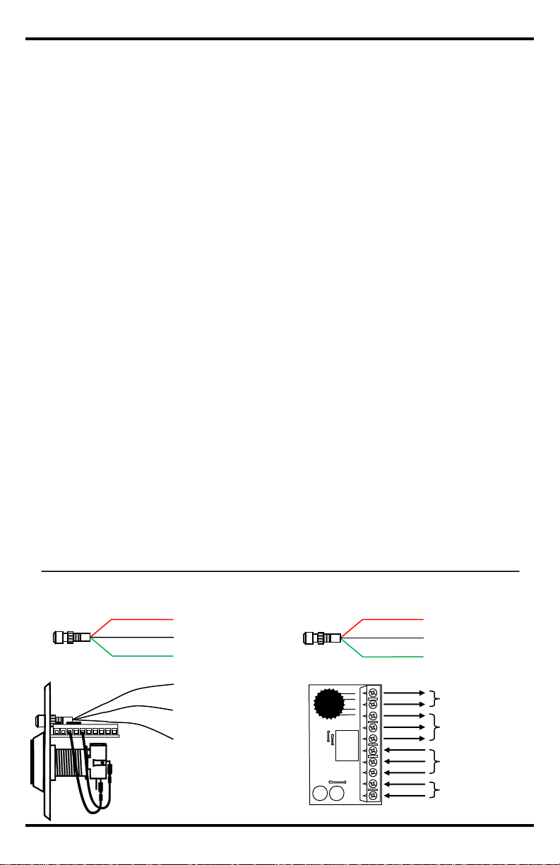
(–)
(+)
*The polarity of the LED must be observed.
Green/white wire (N.C.)
(Lug closest to plate)
Blue/white wire (N.O.)
(Lug farthest from plate)
White wire (COM)
Max. 10A@125~250 VAC
Green wires (light)*
(12VDC or 24VDC)
SECO-LARM U.S.A., Inc. 3
Page 4
ENFORCER Pushbutton Request-to-Exit Plates
The additional LED on the SD-7623-GSTQ serves as a status indicator. It may toggle between ‘off’ and
‘on’ (either red or green) or it may toggle between ‘red’ and ‘green’. As a status indicator, it could
indicate that the lock has entered the timed unlock state after the button has been pressed. On doors
with a door position monitoring output, the status LED could indicate that the door is unlocked or that
the door is opened, returning to standby only after the door has been closed and/or relocked.
1. Follow the wiring instructions for the SD-7202GC-PTQ (see page 3).
2. Decide on the role of the status LED (see above):
a. For status LED off in standby mode (pushbutton LED on), turning on when button is pressed (with
pushbutton LED turning off), then returning to standby mode when timer delay ends (see Fig. 7):
i. Connect the red (for red LED) or green (for green LED) wire of the status LED to the timer
module’s N.O. relay output terminal (the other colored wire will be unused).
ii. Connect the black wire of the status LED to the timer module’s negative (–) power input.
b. For status LED (and pushbutton LED) normally on in standby mode, with status LED changing
colors when button is pressed, then returning to standby mode when timer delay ends (see Fig. 8):
i. Connect one red (or green) wire of the status LED to the timer module’s N.O. relay output
terminal.
ii. Connect the other colored wire of the status LED to the timer module’s N.C. relay output
terminal.
iii. Connect the black wire of the status LED to the timer module’s negative (–) power input.
Important Note:
A. When using a 24VDC power supply, a resistor (included) must be wired in-line with
the status LED’s black wire.
B. Suggested wiring assumes a single power supply (see Fig. 10). Timer module’s relay
output N.C. terminal must be connected to the controlled device’s power input
positive (+) terminal and timer module’s relay output COM terminal must be connect
to the power supply’s positive (+) terminal.
3. Set the time of the timer module between 1~180 sec via the trimpot (see Fig.6). Turn clockwise to
increase and counterclockwise to decrease. Test to ensure the timer is set correctly.
Wiring the SD-7623-GSTQ (with LED and timer module):
Red – to Relay Output
or unused
Black – to Power Input
negative (–)
1
Green – to Relay Output
or unused
Figure 7
LED – Standby ‘Off’, Door Unlocked ‘Red’
Timer Module Relay O/P N.O.
Black (–)
Red (+)
Green (+)
Timer Module Power I/P (–)
1
Unused
Figure 8
LED Standby ‘Green,’ Door Unlocked ‘Red’
Timer Module Relay O/P N.O.
Timer Module Relay O/P N.C.
Timer Module Power I/P (–)
1
Red (+)
Black (–)
Green (+)
Figure 9 – Side View
Figure 10 – Timer Module Top View
Buzzer
Output
Relay Output
(3A@24VDC)
Trigger Input
(Factory prewired)
Power Input 12 or 24
VDC (non-polarized)
(N.O.)
(N.C.)
(COM)
(COM)
(N.O.)
(N.C.)
(+)
(–)
Note: Terminal legend can be found on back of PCB.
1
Use included resistor when connecting to 24VDC.
4 SECO-LARM U.S.A., Inc.
Page 5

ENFORCER Placas de botón para salida
Modelo
SD-7202GC-PEQ
SD-7223GW-LQ
SD-7202GC-PTQ
SD-7623-GSTQ
Operación de voltaje
12 o 24V C.C.
Corriente
10A@250VCA
3A@V C.C.
Placa frontal
Inoxidable cepillado
Plastico blanco
Inoxidable cepillado
Temperatura de operación
-40°~167° F (-40°~75° C)
Temporizador integrado
No
Si
Indicador de estatus LED
No
No
No
Si
Dimensiones
4½”x2¾” (11.4x7.6 cm)
Peso
3.7-oz (105g)
2.2-oz (62g)
4.7-oz (133g)
5.1-oz (144g)
Especificaciones:
Cambio de la placa de mensaje:
1x
Placa de botón para salida
2x
Tornillos de placa de pared
5x
5x
2x
2x
Cables de color:
(SD-7202GC-PEQ)
(SD-7223GW-LQ)
(SD-7202GC-PTQ)
(SD-7623-GSTQ)
1x
Manual de instalación
1x
Foco LED de repuesto
1x
Resistor para 24V C.C.
(solo SD-7623-GSTQ)
2x
Placas de mensaje de
reemplazo (español, francés)
Figura 1
Montaje de
interruptor y foco
EMPUJE
Figura 3
Lista de partes:
Nota: Esto debe realizarse antes de conectar cualquier
alambre.
1. Con cuidado gire el montaje del interruptor y del foco en
contra de las manecillas del reloj alrededor de 20° (vea la
Fig. 1), y después jálelo hacia afuera del tubo negro (vea
la Fig. 2).
2. Inserte el extremo sin punta de una herramienta pequeña
o una varilla (por ejemplo, un desarmador o una pluma
de alrededor, ~3/8” (10mm) de diámetro) en el tubo negro
(vea la Fig. 3). Debe deslizarse fácilmente hacia adentro
hasta que haga contacto con la parte interna del montaje
frontal de la placa de lente/mensaje. Empuje el montaje
frontal de la placa de lente/mensaje con su herramienta
hasta que salga (vea la Fig. 4). Tenga cuidado de no
perder el resorte.
3. Quite la lente verde transparente y reemplace la placa
de mensaje.
4. Asegúrese que la dirección de la placa de mensaje sea
la correcta.
5. Coloque el montaje de la lente en su lugar y remplace el
montaje del interruptor/foco.
SD-7202GC-PEQ
Botón grande, iluminado con leyenda “PUSH TO EXIT”
Idioma de los mensajes se pueden cambiar fácilmente a
español o francés
Cable de color de 12 pulgadas con terminales de horquilla
fáciles de sujetar para una rápida instalación
LED de más de 50,000 horas de iluminación
Incluye placa singular de acero inoxidable (menos SD-
7223GW-LQ, que es plástico blanco)
SD-7223GW-LQ
SD-7202GC-PTQ
SD-7623-GSTQ
Similar al SD-7202GC-PEQ, pero con
placa blanca de plástico
Similar al SD-7202GC-PEQ, pero con
temporizador adicional (1-180 seg) y
salida de zumbador
Similar al SD-7202GC-PTQ, pero con
indicador de estatus LED
personalizable adicional
Figura 2
Carcasa
enroscada
Montaje de
interruptor y
foco
Placa de
mensaje
PRESIONE
PARA
SALIR
Lentes verdes
transparentes
Figura 4
Modelos:
SECO-LARM U.S.A., Inc. 5
Page 6

ENFORCER Placas de botón para salida
Entrada de poder
12 o 24V C.C.
(sin polaridad)
IMPORTANTE
Usuarios y instaladores de este producto son responsables de asegurar que la instalación y configuración de este
producto cumpla con todas leyes y códigos nacionales, de estado y locales relacionadas a dispositivos de bloqueo y
salida. SECO-LARM no se hace responsable del uso de este producto en violación de cualquier ley o código actual.
Salida de zumbador
Salida de relevador
(3A@24V C.C.)
Entrada de interruptor
(Cableado en fabrica)
Nota: Leyenda de terminales se puede encontrar en la parte
posterior del PCB.
Para ajustar el tiempo (1~180
seg), gire el potenciómetro hacia
la derecha para aumentar, hacia
la izquierda para disminuir.
Potenciómetro
de ajuste del
temporizador
Figura 6
(N.A.)
(N.C.)
(COM)
(COM)
(N.A.)
(N.C.)
(+)
(–)
Cableado de SD-7202GC-PTQ (con temporizador):
1. Para alimentar el LED, conecte 1 cable VERDE a cada uno
de los conectores tipo espada de color latón en cada lado
del montaje del interruptor negro y foco (vea la Fig. 5 arriba)
y conecte el otro lado de cada cable VERDE a una fuente de
12 o 24 V C.C. La polaridad del LED debe observarse.
2. Conecte 12 o 24V C.C. (sin polaridad) a los terminales de
entrada de poder del temporizador (vea la Fig. 6).
3. Conecte un dispositivo N.A. o N.C. al bloque de terminal
de salida del relevador como se desee
(3A@24V C.C. max.).
4. Conecte zumbador al terminal de salida de zumbador si se
desea.
5. Establezca el tiempo de temporizador entre 1~180 seg a
través del potenciómetro. Gire el potenciómetro hacia la
derecha para aumentar, hacia la izquierda para disminuir.
Pruébelo para asegurarse que el temporizador se haya
establecido correctamente.
Cableado de SD-7202GC-PEQ y SD-7223GW-LQ:
1. Corra cuatro alambres a través de la pared a una caja posterior
singular:
a. Dos alambres para 12V C.C. o 24V C.C. para la luz.
b. Un alambre desde la terminal N.A. o N.C. de un dispositivo
como una alarma o un sistema de control de acceso, el cual
pueda abrir una cerradura controlada eléctricamente.
c. Un alambre desde la terminal COM de ese dispositivo.
2. Conecte cuatro alambres de color (incluidos) al interruptor
(vea la Fig. 5):
a. Para alimentar el LED, conecte 1 cable VERDE a cada uno de
los conectores tipo espada de color latón en cada lado del
interruptor negro. La polaridad del LED debe observase.
b. Conecte el cable VERDE/BLANCO al conector N.C. en el interruptor negro (si se necesita).
c. Conecte el cable AZUL/BLANCO al conector N.A. en el interruptor negro (si se necesita).
d. Conecte el cable BLANCO al conector COM en el interruptor negro.
3. Conecte los cables de color a los cables de la alarma o del sistema de control de acceso a la fuente de alimentación
de la luz (vea la Fig. 5):
a. 2x cables VERDES – A una fuente de 12 o 24 V C.C. La polaridad del LED debe observarse.
b. Cable VERDE/BLANCO – Al terminal N.C. de la alarma o del sistema de control de acceso (si se necesita).
c. Cable AZUL/BLANCO – Al terminal N.A. de la alarma o del sistema de control de acceso (si se necesita).
d. Cable BLANCO – Al terminal COM de la alarma o del sistema de control de acceso.
4. Atornille la placa en la caja posterior, teniendo cuidado de no enredar los alambres.
(–)
Figura 5
(+)
Verde/blanco (N.C.)
(Orejeta mas cercano a placa)
*La polaridad del LED debe observarse.
Cable azul/blanco (N.A.)
(Orejeta más lejano de placa)
Cable blanco (COM)
Máx. 10A@125~250VCA
Cables verdes (foco)*
(12V C.C. o 24V C.C.)
6 SECO-LARM U.S.A., Inc.
Page 7

ENFORCER Placas de botón para salida
El LED adicional en el SD-7623-GSTQ funciona como indicador de estatus. Se puede conmutar entre ‘apagado’ y
‘encendido’ (sea el rojo o verde) o se puede conmutar entre ‘rojo’ y ‘verde’. Como indicador de estatus, se puede usar para
indicar que la cerradura haya entrado en el estado de desbloqueo programado después de que el botón haya sido
presionado. En puertas con una salida de monitoreo de posición de puerta, el LED de estatus indicara que la puerta esta
desbloqueada o que la puerta está abierta, regresando al modo de espera solo después de que la puerta se haya cerrado
y bloqueado de nuevo.
1. Siga las instrucciones de cableado del SD-7202GC-PTQ (vea la pagina 3).
2. Decida la acción del estatus de LED (vea arriba).
a. Para LED de estatus apagado en modo de espera (LED del botón encendido), encender cuando se presione el
botón (con LED del botón apagándose), luego volviendo a modo de espera cuando la demora del temporizador se
termine (vea Fig.7):
i. Conecte el cable rojo (para luz rojo) o verde (para luz verde) del LED de estatus al terminal de salida del
relevador N.A del modulo de temporizador (el otro cable de color no será usado).
ii. Conecte el cable negro del LED de estatus a la entrada de poder negativa del modulo del temporizador.
b. Para LED de estatus (y LED de botón) normalmente encendido en modo de espera, con LED de estatus cambiando
colores cuando el botón de presione, luego volviendo a modo de espera cuando la demora del temporizador se
termine (vea Fig. 8):
i. Conecte un cable rojo (o verde) del LED de estatus al terminal de salida del relevador N.A. del bloqueo de
temporizador.
ii. Conecte el otro cable de color al LED de estatus al terminal de salida del relevador N.C. del bloqueo de
temporizador.
iii. Conecte el cable negro del LED de estatus a la entrada de poder negativa del modulo del temporizador.
Nota importante:
A. En cuando usando fuente de 24V C.C., un resistor (incluido) se debe cablear al circuito negativo para
el LED de estatus.
B. Cableado sugerido asume una sola fuente de alimentación (vea la Fig. 10). Terminal de la salida N.C.
del relevador del modulo del temporizador debe estar conectado al terminal positivo (+) de la entrada
de alimentación del dispositivo controlado, y el terminal de la salida COM del relevador del modulo
del temporizador deber ser conectado al terminal positivo (+) de la fuente de alimentación.
3. Establezca el tiempo de temporizador entre 1~180 seg a través del potenciómetro (vea Fig. 6). Gire el potenciómetro
hacia la derecha para aumentar, hacia la izquierda para disminuir. Pruébelo para asegurarse que el temporizador se haya
establecido correctamente.
Cableado para SD-7623-GSTQ (con LED y temporizador):
Salida de
zumbador
Salida de relevador
(3A@24V C.C.)
Entrada de interruptor
(Cableado en fabrica)
Entrada de poder
12 o 24V C.C. (sin
polaridad)
(N.A.)
(N.C.)
(COM)
(COM)
(N.A.)
(N.C.)
(+)
(–)
Rojo – a salida de rele.
o no utilizado
Negro – al entrada poder
negativo (–)
1
Verde – a salida de rele.
o no utilizado
Figura 7
LED – En espera ‘Apagado’, Puerta desbloqueada ‘Rojo’
Relevador de temporizador
O/P N.A.
Negro (–)
Rojo (+)
Verde (+)
Poder de relevador de
temporizador I/P (–)
1
No utilizado
Figura 8
LED – En espera ‘Verde,’ Puerta desbloqueada ‘Rojo’
Relevador de temporizador
O/P N.C.
Poder de relevador de
temporizador I/P (–)
1
Relevador de temporizador
O/P N.A.
Rojo (+)
Negro (–)
Verde (+)
Figure 9 – Vista lateral
Figure 10 – Vista superior de temporazidor
Nota: Leyanda de terminales se puede encontrar en
la parte posterior del PCB.
1
Use resistor incluido cuando conectando a 24V C.C.
SECO-LARM U.S.A., Inc. 7
Page 8

ENFORCER Plaques de sortie de bouton poussoir
Modèle
SD-7202GC-PEQ
SD-7223GW-LQ
SD-7202GC-PTQ
SD-7623-GSTQ
Tension de fonctionnement
12 o 24VCC
Courant
10A@250VCA
10A@250VCA
Plaque
Acier inoxydable
brossé
Plastique blanc
Acier inoxydable brossé
Température de
fonctionnement
-40°~167° F (-40°~75° C)
Minuterie intégrée
Non
Oui
Indicateur d’état LED
Non
Non
Non
Oui
Dimensions
4½”x2¾” (11.4x7.6 cm)
Poids
3.7-oz (105g)
2.2-oz (62g)
4.7-oz (133g)
5.1-oz (144g)
Caractéristiques:
Modèles:
1x
Plaque de sortie de bouton
poussoir
2x
Vis de plaque murale
5x
5x
2x
2x
Fils de sortie de couleur:
(SD-7202GC-PEQ)
(SD-7223GW-LQ)
(SD-7202GC-PTQ)
(SD-7623-GSTQ)
1x
Manuel d’installation
1x
Ampoule LED de rechange
1x
Résistance pour 24VCC
(seulement SD-7623GSTQ)
2x
Plaques de message de
remplacement (français,
espagnol)
Liste des pièces:
SD-7202GC-PEQ
Bouton large illuminé marqué “PUSH TO EXIT”
Changer le texte du bouton facilement à pied d’oeuvre
pour texte français ou espagnol
Fils de sortie 12 pouces à code couleur compris avec
cosses à fourche pour installation rapide
LED donne plus de 50,000 heures d’èclairage
Plaque de prise simple inox comprise (à l’exception de
SD-7223GW-LQ, qui est plastique blanc)
SD-7223GW-LQ
SD-7202GC-PTQ
SD-7623-GSTQ
Même que SD-7202GC-PEQ, mais
avec plaque de plastique blanc
Même que SD-7202GC-PEQ, mais
avec minuterie supplémentaire
(1-180 s) et sortie avertisseur
Même que SD-7202GC-PTQ, mais
avec indicateur d’état LED
personnalisable supplémentaire
Figure 2
Interrupteur
et lampe
Monture
filetée
Figure 1
Interrupteur et
lampe
Lentille verte
transparente
Figure 4
Plaque de
message
POUSSER
POUR
SORTIR
Pousser
Figure 3
Changer la plaque de message:
NB: Cela devrait être fait avant de brancher les fils.
1. Avec un minimum de force, tourner l’interrupteur
et lampe assemblage vers la gauche approx. 20°
(voir la Fig. 1), et puis enlever du tube noir (voir
la Fig. 2).
2. Inserer le bout d’un outil non-pintu (ex., arriere
d’un stylo, tournevis, etc., de diamètre approx.
~3/8” (10mm)) dans le tube noir (voir la Fig. 3). Il
glissera jusqu’au point où il touché la lentille
verte. Pousser avec l’outil, et la lentille se
detachera de l’encadrement (voir la Fig. 4). Faire
attention de ne pas perdre le ressort.
3. Enlever la lentille verte transparente et insérer la
plaque de message souhaité.
4. Vérifier l’orientation de la plaque de message est
correct.
5. Aligner l’ensemble de lentille en place et
remplacer l’ensemble interrupteur/lampe.
8 SECO-LARM U.S.A., Inc.
Page 9

ENFORCER Plaques de sortie de bouton poussoir
Câblage pour SD-7202GC-PTQ (avec module minuterie):
Câblage pour SD-7202GC-PEQ et SD-7223GW-LQ:
1. Passer quatre fils électriques au travers du mur jusqu’à une
boîte de prise simple:
a. Deux fils d’une source d’alimentation 12VCC ou 24VCC
pour la lumière du bouton poussoir.
b. Un fil pour brancher à la borne N.O. ou N.F. d’un
système d’alarme ou de contrôle d’accès capable de
contrôler une serrure électrique.
c. Un fil pour brancher à la borne COM du dispositif
mentionné ci-dessus.
2. Brancher les fils de couleur (inclus) à l’interrupteur (voir la
Fig. 5):
a. Pour alimenter le LED du bouton poussoir, brancher un fil VERT à chacun des cosses de couleur
laiton sur les côtés de l’interrupteur noir.
b. Brancher le fil VERT/BLANC au connecteur N.F. sur l’interrupteur noir (si nécessaire).
c. Brancher le fil BLEU/BLANC au connecteur N.O. sur l’interrupteur noir (si nécessaire).
d. Brancher le fil BLANC au connecteur COM sur l’interrupteur noir.
3. Brancher les fils de couleur aux fils du système d’alarme ou de contrôle d’accès, et aux fils de
l’alimentation de la lumière (voir la Fig. 5):
a. 2x fils VERTS – À une source de 12 ou 24 VCC. La polarité du LED doit être respectée.
b. Fil VERT/BLANC – À la borne N.F. du système d’alarme ou de contrôle d’accès (si nécessaire).
c. Fil BLEU/BLANC – À la borne N.O. du système d’alarme ou de contrôle d’accès (si nécessaire).
d. Fil BLANC – À la borne COM du système d’alarme ou de contrôle d’accès.
4. Visser la plaque sur la boîte de prise. Faire attention de ne pas pincer les fils.
IMPORTANT
Utilisateurs et installateurs de ce produit sont responsables de s'assurer que l'installation et la configuration de ce prod uit
est conforme à toutes lois et codes nationaux, d'état et locales relatifs au dispositifs de verrouillage et d'évacuation.
SECO-LARM ne sera pas responsable de l'utilisation de ce produit en violation des lois ou des codes en vigueur.
Figure 5
Sortie
avertisseur
Relais sortie
(3A@24VCC)
Entrée de
déclenchement
(précâblé à l’usine)
Entrée d’alimentation
12 o 24VCC (nonpolaire)
(N.O.)
(N.F.)
(COM)
(COM)
(N.O.)
(N.F.)
(+)
(–)
NB: La légend du bornier se trouve sur le dos de la carte de circuit.
Pour régler la minuterie (1~180 s),
tourner le potentiometer à droite
pour augmenter, et à gauche pour
Potentiomètre
de rélage
minuterie
Figure 6
(–)
(+)
*La polarité du LED doit être respectée.
Fil vert/blanc (N.F.)
(Cosse la plus proche de la plaque)
Fil bleu/blanc (N.O.)
(Cosse la plus éloignée de la plaque)
Fil blanc (COM)
Max. 10A@125~250 VCA
Fils verts (lumière)*
(12VCC ou 24VCC)
1. Pour alimenter le LED du bouton poussoir, brancher un fil
VERT à chacun des cosses de couleur laiton sur les côtés
de l’interrupteur noir et lampe (see Fig. 5 above) et brancher
l’autre côté de chaque fil VERT à un source de 12 ou 24
VCC. La polarité du LED doit être respectée.
2. Brancher 12 o 24VCC (non-polaire) aux bornes d’entrée
d’alimentation du module minuterie (voir la Fig. 6).
3. Brancher dispositif N.O. ou N.F., comme un verrou
électromagnétique ou alarme, au bloc de borne de sortie
de relais comme vous le désirez (3A@24VCC max.).
4. Brancher l’avertisseur au borne du sortie avertisseur si
désiré.
5. Régler le module minuterie entre 1~180 s via le
potentiomètre. Tourner à droite pour augmenter, et à
gauche pour diminuer. Tester pour assurer la minuterie
est bien régler.
SECO-LARM U.S.A., Inc. 9
Page 10

ENFORCER Plaques de sortie de bouton poussoir
Figure 8
LED - Mode d’attente ‘Vert,’ Porte ouverte ‘Rouge’
Figure 7
LED – Mode d’attente ‘Éteinte’, Porte ouverte ‘Rouge’
Relais de module minuterie
O/P N.O.
Noir (–)
Rouge (+)
Vert (+)
Alimentation de module
minuterie I/P (–)
1
Inutilisé
Relais de module minuterie
O/P N.F.
Alimentation de module
minuterie I/P (–)
1
Relais de module minuterie
O/P N.O.
Rouge (+)
Noir (–)
Vert (+)
NB: La légend du bornier se trouve sur le dos de la
carte de circuit.
1
Utiliser inclus résistance lors de la connexion à 24VCC.
La LED supplémentaire sur le SD-7623-GSTQ fonctionnes comme d'indicateur d’état. Il peut commuter entre
'éteinte' et 'allumé' (rouge ou vert) ou il peut commuter entre 'rouge' et 'verte'. Comme un indicateur d'état,
cela pourrait indiquer que le verrouillage est entré dans l'état de déverrouillage temporisé après que le bouton
a été pressé. Sur les portes avec une position de la porte de sortie de contrôle, LED d'état peut indiquer que
la porte est déverrouillée ou que la porte est ouverte, retourner en mode d'attente seulement après que la
porte a été fermée et/ou reverrouillé.
1. Suivre les instructions de câblage pour SD-7202GC-PTQ (voir la page 3).
2. Décider sur le rôle de la LED d’état (voir ci-dessus):
a. Pour LED d’état éteinte en mode d’attente (LED du bouton poussoir allumé), allumer lorsque le bouton
est enfoncé (avec LED du bouton poussoir éteindre), puis retourner en mode d’attente lorsque le retard
de la minuterie se termine (voir la Fig. 7):
i. Brancher le fil rouge (pour LED rouge) ou le fil vert (pour LED vert) de la LED d’état à la borne du
relais sortie N.O. du module minuterie (l’autre fil de couleur ne sera pas utilisée).
ii. Brancher le fil noir de la LED d’état au l’entrée de alimentation negatif (–) du module minuterie.
b. Pour LED d’état (et LED du bouton poussoir) normalement allumé en mode d’attente, avec LED d’état
changeant de couleurs lorsque le bouton est enfoncé, puis retourner en mode d’attente lorsque le retard
de la minuterie se termine (voir la Fig. 8):
i. Brancher un fil rouge (ou vert) de la LED d’état à la borne du relais sortie N.O. du module minuterie.
ii. Brancher l’autre fil de colour de la LED d’état à la borne du relais sortie N.F. du module minuterie.
iii. Brancher le fil noir de la LED d’état au l’entrée de alimentation negatif (–) du module minuterie.
Note importante:
A. Lorsque vous utilisez une alimentation 24VCC, une résistance (inclus) doit être branché
en ligne avec la fil noir de la LED d’état.
B. Câblage suggérés supposent une seule alimentation (voir la Fig. 10). Borne de sortie N.F.
de relais du module minuterie doit être connecté au borne positive (+) de l'entrée
d'alimentation du dispositif commandé, et le borne de sortie COM du module minuterie
doit être connecté au borne positive (+) de la source d'alimentation.
3. Régler le module miniterie entre 1~180 s via le potentiomètre (voir la Fig.6). Tourner à droite pour
augmenter, et à gauche pour diminuer. Tester pour assurer la minuterie est bien régler.
Sortie
avertisseur
Relais sortie
(3A@24VCC)
Entrée de
déclenchement
(précâblé à l’usine)
Entrée d’alimentation
12 ou 24VCC (nonpolaire)
(N.O.)
(N.F.)
(COM)
(COM)
(N.O.)
(N.F.)
(+)
(–)
Figure 9 – Vue de côté
Figure 10 – Vue de dessus de module minuterie
Rouge – au relais sortie ou
……… inutilisé
Vert – au relais sortie ou
inutilisé
Noir – au entrée alimentation
négatif (–)
1
Câblage pour SD-7623-GSTQ (avec LED et module minuterie):
10 SECO-LARM U.S.A., Inc.
Page 11

ENFORCER Pushbutton Request-to-Exit Plates
Post-Mount
No-Touch Sensor
Outdoor No-Touch Sensor
with Mechanical Override
SD-9963-KSGQ
SD-9263-KSVQ
Also Available from SECO-LARM®:
Indoor No-Touch Sensor
Flush Mount RTE Plate
SD-927PKC-NEQ
SD-7286-GWQ
Mushroom RTE Plate
Single-Gang Mortise Cylinder Key Switch
SD-7201GC-PEQ
SD-72081-6MQ
SECO-LARM U.S.A., Inc. 11
Page 12

ENFORCER Pushbutton Request-to-Exit Plates
SECO-LARM
®
U.S.A., Inc.
16842 Millikan Avenue, Irvine, CA 92606
Website: www.seco-larm.com
Phone: (949) 261-2999 | (800) 662-0800
Email: sales@seco-larm.com
GARANTIE: Ce produit SECO-LARM est garantie contres défaults de production ou de matériaux qui apparaît en cours de
fonctionnement typique pendant un (1) an à la date d’acquisition par le client consommateur original.
AVIS: SECO-LARM se réserve le droit de changer les spécifications sans avis.
© 2014 SECO-LARM U.S.A., Inc. Tous droits réservés.
NOTICE: The information and specifications printed in this manual are current at the time of publication. However, the
SECO-LARM policy is one of continual development and improvement. For this reason, SECO-LARM reserves the right to
change specifications without notice. SECO-LARM is also not responsible for misprints or typographical errors.
Copyright © 2014 SECO-LARM U.S.A., Inc. All rights reserved. This material may not be reproduced or copied, in whole or
in part, without the written permission of SECO-LARM.
®
PITSW1
Order Part# 763-154-7%
MiSD-7200series_140910B.docx
WARRANTY: This SECO-LARM product is warranted against defects in material and workmanship while used in normal
service for one (1) year from the date of sale to the original customer. SECO-LARM’s obligation is limited to the repair or
replacement of any defective part if the unit is returned, transportation prepaid, to SECO-LARM. This Warranty is void if
damage is caused by or attributed to acts of God, physical or electrical misuse or abuse, neglect, repair or alteration,
improper or abnormal usage, or faulty installation, or if for any other reason SECO-LARM determines that such equipment
is not operating properly as a result of causes other than defects in material and workmanship. The sole obligation of
SECO-LARM and the purchaser’s exclusive remedy, shall be limited to the replacement or repair only, at SECO-LARM’s
option. In no event shall SECO-LARM be liable for any special, collateral, incidental, or consequential personal or property
damage of any kind to the purchaser or anyone else.
GARANTÍA: Este producto SECO-LARM tiene garantía en contra de defectos de material y mano de obra siempre y
cuando se utilice en un servicio normal por un periodo de un (1) año a partir de la fecha de venta al cliente consumidor
final. La obligación de SECO-LARM está limitada a reparar o reemplazar cualquier parte defectuosa si la unidad se
regresa a SECO-LARM, con el costo de transporte pagado por adelantado.
Esta Garantía se invalidará si se causa algún daño o se atribuye a actos de Dios, mal uso o abuso físico o eléctrico,
negligencia, reparación o alteración, uso no apropiado o anormal, o por una instalación defectuosa, o si por cualquier otra
razón que SECO-LARM establezca que determinado equipo no está operando de manera apropiada como resultado de
causas distintas a los defectos del material o la mano de obra. La única obligación de SECO-LARM y el resarcimiento
exclusivo del comprador deberá limitarse sólo al reemplazo o reparación, de acuerdo con la opción que brinde SECOLARM. Bajo ninguna circunstancia, SECO-LARM será responsable de cualquier daño especial, colateral, incidental o
consecuencial personal o daños de propiedad de cualquier tipo al comprador o a cualquier otro.
NOTA: La información y las especificaciones impresas en este manual están vigentes al momento de su publicación. Sin
embargo, la política de SECO-LARM es aquella de desarrollo y mejora continuos; por lo tanto, SECO-LARM se reserva el
derecho a cambiar las especificaciones sin previo aviso. SECO-LARM tampoco es responsable por los errores de
impresión o tipográficos.
Copyright © 2014 SECO-LARM U.S.A., Inc. Todos los derechos reservados. Este material no puede reproducirse ni
copiarse, en su totalidad o por partes, sin el permiso por escrito de SECO-LARM.
12 SECO-LARM U.S.A., Inc.
 Loading...