

Page 1
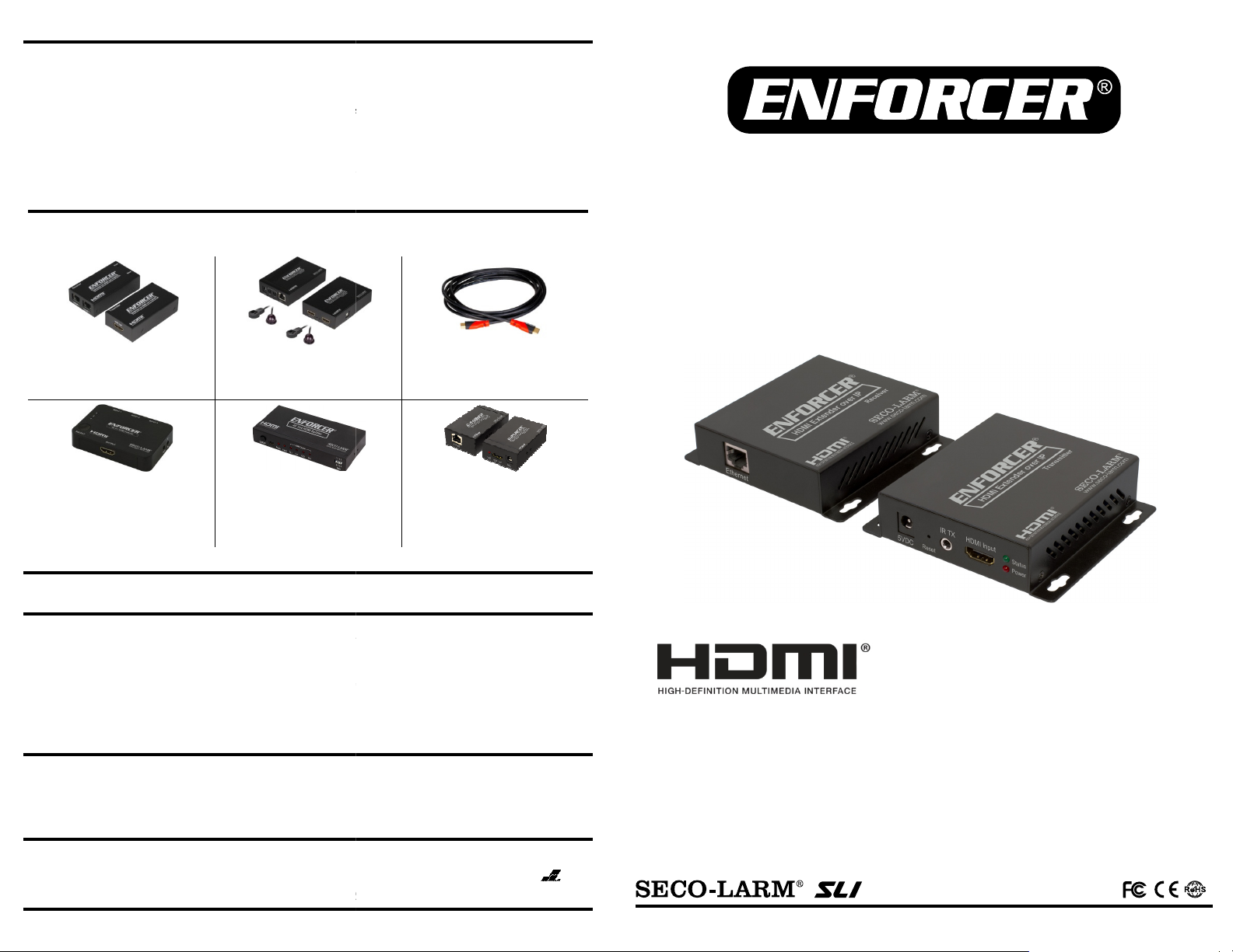
ENFORCER HDMI Extender over IP
NOTICE:
The SECO
-
LARM policy is one of continual development and improvement. For that reason, SECO
LARM is not responsible for misprints. Trademarks are
LARM U.S.A., Inc. All rights reserved. This material may not be reproduced or copied, in whole or
WARRANTY:
This SECO
-
LARM product is warranted against defects in material and workmanship while used in normal
from the date of sale to the original customer. SECO
ve part if the unit is returned, transportation prepaid
damage is caused by or attributed to acts of God, physical or electrical misuse or abuse, neglect, repair or alteration,
nstallation, or if for any other reason SECO
s in material and workmanship.
limited to the replacement or repair only, at SECO
LARM be liable for any special, collateral, incidental, or consequential personal or property
damage of any kind to the purchaser or anyone else.
SECO
-
LARM
16842
Millikan Avenue, Irvine, CA 92606
Website: www.seco
Tel: (949) 261
-
2999 | (800) 662
-
0800 Email: sales@seco
HDMI, the HDMI Logo and High
-
Definition Multimedia Interface are trademarks or registered trademarks of HDMI Licensing
Also Available from SECO
-
LARM:
MVE-AH010Q
MVE-AH030Q
HDMI Extender over Single
MVS-AH31
-
01NQ
MVD-AH12-
01Q
s
and MAC Address Continued:
4. Select "System Settings" and change the last segment of the IP address shown to a unique
Change the final digits of the MAC address from the default
to a unique hexadecimal number between 01 and FF.
described in "Installation" on pg. 4 and
-
LARM
-
larm.com
-
larm.com
High-Speed
MVE-AH030AQ
•
•
HDMI, the HDMI Logo and High
-
Definition Multimedia Interface are trademarks or registered trademarks of HDMI Licensing LLC in the United
Changing the IP
number between 1 and 254.
5.
RX: 00:0b:78:00:60:02)
6. Click "Apply" to enable the changes.
7. Repeat for each additional TX/RX and then install as
consult the diagrams on pgs. 5-6 as necessary.
HDMI Extender over Dual
Cat5e/6
Cat5e/6
MVS-AH51-01NQ
4K HDMI Switchers
MVD-AH14-01Q
MVD-AH18-01Q
4K HDMI Splitter
(TX: 00:0b:78:00:60:01,
HDMI Cables
Basic HDMI Extender over
Single Cat5e/6
MVE-AHMPM-01NQ
HDMI® Extender Over IP
Manual
LLC in the United States and other countries.
service for the one (1) year
or replacement of any defecti
improper or abnormal usage, or faulty i
is not operating properly as a result of causes other than defect
SECO-LARM and the purchaser’s exclusive remedy shall be
option. In no event shall SECO-
reserves the right to change specifications without notice. SECOthe property of SECO-LARM U.S.A., Inc. or their respective owners.
Copyright © 2016 SECOin part, without the written permission of SECO-LARM.
8
®
U.S.A., Inc.
-LARM’s obligation is limited to the repair
, to SECO-LARM. This Warranty is void if
-LARM determines that such equipment
The sole obligation of
-LARM’s
MI_MVE-AHMPM-01NQ_160426.docx
SECO-LARM U.S.A., Inc.
PICSN6
Support
Extends HDMI over one Cat5e/6 cable or
IP network
• Supports One-to-One, One-to-Many, and
Many-to-Many applications
• Supports cascaded installation
IR Support (38kHz~56kHz)
• HDCP Compliant
• Transmitter (MVE-AHMPM-01NTQ) and
receiver (MVE-AHMPM-01NRQ) also
available separately
States and other countries.
Page 2
ENFORCER HDMI Extender over IP
Specifications
................................
................................
................................
............................
2
The MVE
-
AHMPM
-
01NQ HDMI Extender over IP extends the range of HDMI signals by using an
1x Transmitter
1x IR
Transmitter
2x Power adapters
4x Mounting screws
1x Receiver
1x IR
Receiver
1x Manual
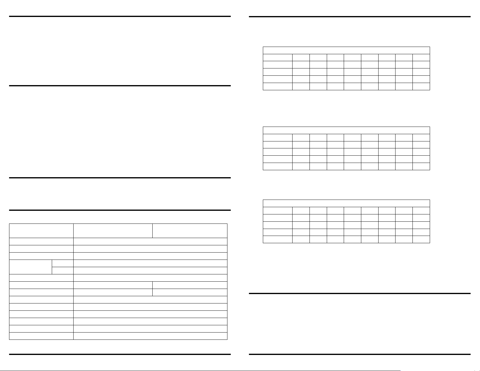
Transmitter
Receiver
Maximum video resolution
1080p
Deep
color 24-bit
Video formats supported
DTV/HDTV: 480i, 576i, 480p, 576p, 720p, 1080i, 1080p
Cat6 390ft (120m)
Cat5e
360ft (110m)
IP addressing
Static or dynamic
Default IP address (static)
192.168.168.55
192.168.168.56
Default MAC
address
00:0b:78:00:60:01
00:0b:78:00:60:02
IR frequency
38kHz~56kHz
Operating voltage
5VDC
@1A
Power consumption
3W
Operating temperature
23°~
95° F (
-5°~35° C)
Dimensions
41/16"
x311/16"x1" (104x94
x25mm)
Weight
7.8-oz (221g)
5. By default VLAN1 will be configured and all ports on the switch will be
assigned to it.
VLAN1
Interface
P1 P2 P3 P4 P5 P6 P7 P8
Member
x x x x x x x x
Tagged
Untagged
x x x x x x x x
PVID x x x x x x x x
VLAN1
Interface
P1 P2 P3 P4 P5 P6 P7 P8
Member
x x x x
Tagged
Untagged
x x x x x x x x
PVID
VLAN2
Interface
P1 P2 P3 P4 P5 P6 P7 P8
Member
x x x x
Tagged
Untagged
x x x x x x x x
PVID
1. When there is more than one pair of transmitters/receivers connected to a switch/router, the IP
VLAN Setup Continued:
ENFORCER HDMI Extender over IP
active transmitter and receiver to send video and audio over a single Cat5e/6 cable. The HDMI
Extender over IP supports IR signals using the included IR transmitter and receiver, allowing
remote control use from one end of an installation to control a device such as a media player or
DVD player at the opposite end of the installation. The MVE-AHMPM-01NQ supports One-to-One,
One-to-Many, and Many-to-Many installation via VLAN, as well as a cascading installation, allowing
the connection of multiple units for extended range.
Parts List .................................................................................................................................... 2
Dimensions ................................................................................................................................ 3
Overview .................................................................................................................................... 3
Installation ................................................................................................................................. 4
Sample Application—One-to-One ............................................................................................. 4
Sample Application—One-to-Many, Switch/Router ................................................................... 5
Sample Application—Many-to-Many, VLAN Switch .................................................................. 6
VLAN Setup ........................................................................................................................... 6-7
Changing the IP and MAC Address ....................................................................................... 7-8
a. Example default VLAN configuration:
b. Make note of which ports the transmitters and receivers will be connected to.
c. Update the ports that will be connected to Transmitter 1 and its associated receivers.
d. For this example, the first 4 ports (P1-P4) will be connected to Transmitter 1 and its
associated receivers by setting the "Member" values for P1-P4.
e. Click "Apply" or "Save" to enable the changes.
6. Create a second VLAN for Transmitter 2 and name it VLAN2.
a. Set the last 4 ports to be on VLAN2 by setting the "Member" values for P5-P8.
Model
Range – 1080p
2 SECO-LARM U.S.A., Inc.
MVE-AHMPM-01NTQ
MVE-AHMPM-01NRQ
b. Click "Apply" or "Save" to enable the changes.
c. Connect Transmitter 2 and its associated receivers to the last 4 ports (P5-P8).
d. Confirm the source from Transmitter 1 is displaying on the receivers connected to P1-P4
and the source from Transmitter 2 is displaying on the receivers connected to P5-P8.
e. If not, recheck the settings on VLAN1 and VLAN2 to make sure they are set correctly and
that the configuration has been saved.
Changing the IP and MAC Address:
address and MAC addresses must be changed for the additional units.
2. Connect a powered transmitter/receiver (TX/RX) to a computer using an Ethernet cable (Note
the computer may not have the same IP address as the transmitter/receiver). The power LED
on the TX/RX should be red and the status LED should be green.
3. Open your web browser to the default link (TX: 192.168.168.55, RX: 192.168.168.56).
SECO-LARM U.S.A., Inc. 7
Page 3

ENFORCER HDMI Extender over IP
Samp
le Application
— Many
-to-
Many, VLAN Switch:
Cable Legend:
For maximum c
able length,
HDMI
VLAN
Capable
VLAN1
VLAN1
Power
HDMI
VLAN2
VLAN2
HDMI
Transmitter 2
Power
Power
IR TX
NOTE:
When setting up a Many
-to-
Many configuration, it will be necessary to use a managed
Power
Transmitter 1
HDMI
IR TX
ENFORCER
*Input/output depends on whether the unit is a transmitter or receiver
Transmitter and receiver have the same dimensions
41/16"
311/16"
29/16"
5VDC
Reset
IR Input/
HDMI Input/
Power
LED
Status
LED
Mounting
holes
Mounting
31/16"
1"
Cat5e/6
HDMI Extender over IP
Adapter
Source
Adapter
see "Specifications"
Switch
Receiver 1
Receiver 2
HDMI
Power
IR
Cat5e/6
Display
IR RX and Remote
Adapter
Display
IR RX and Remote
(104mm)
(65mm)
(78mm)
(94mm)
(25mm)
Source
Adapter
VLAN Setup:
switch that supports VLANs. The following is a generic example as configuration varies by
manufacturer.
VLAN Setup Example
1. Login to the managed switch through its web interface.
2. In this example, an 8-port managed switch (P1-P8) is used to connect 2 transmitters as shown
in "Sample Application — Many-to-Many, VLAN Switch".
3. Look for a menu option or tab labeled "VLAN" or "VLAN Management".
4. Check or click on the option to enable/create VLANs.
6 SECO-LARM U.S.A., Inc.
output*
output*
SECO-LARM U.S.A., Inc.
Input/
output*
holes
3
Page 4

ENFORCER HDMI Extender over IP
Samp
le Application
— One-to-One:
Cable Legend:
NOTE:
For
One-to-Many and Many
-to-
Many
installations, each receiver
/
transmitter's IP and MAC
Power
For maximum cable length,
HDMI
Power
Samp
le Application
— One-to-Many, Switch/Router:
For maximum cable length,
Cable Legend:
HDMI
HDMI
Power
Adapter
Power
LAN
Power
Transmitter 1
HDMI
IR TX
Power
Adapter
HDMI
addresses must be unique. See "Changing the IP and MAC Address" on pgs. 7-8 before
installation.
1. Determine the location where the HDMI Extender over IP units will be installed as well as how
much Cat5e/6 cable will be necessary.
2. Connect the transmitter to the HDMI output of the source device.
3. Connect the transmitter and receiver:
a. If connecting One-to-One, connect one end of the Cat5e/6 cable to the transmitter and
the other end directly to the receiver.
b. If installing with a switch or router, connect one end of the Cat5e/6 cable to the transmitter
and the other end to a switch or router. Then, with a second Cat5e/6 cable connect the
receiver to the other end of the switch or router.
4. Connect the receiver to the HDMI input of the display or other device.
5. Connect one 5VDC adapter to the transmitter and the other to the receiver.
6. Determine which device, if any, will be controlled by remote control.
a. Install the IR transmitter to the IR port near the device to be controlled, pointing the IR
transmitter at its IR sensor.
b. Install the IR receiver to the IR port of the other transmitter/receiver, pointing the IR
receiver in a direct line of sight to where the remote control will be.
c. Point the remote control at the IR receiver when in use.
7. Switch on the HDMI source and display to verify that the system is functioning properly. It
may take up to a minute to sync up the video stream.
ENFORCER HDMI Extender over IP
HDMI
Power
IR
Cat5e/6
Display
Adapter
IR RX and Remote
Receiver 1
Source
HDMI
Power
IR
Cat5e/6
Remote
IR TX
Adapter
Transmitter
Source
see "Specifications"
Receiver
HDMI Display
IR RX
Adapter
4 SECO-LARM U.S.A., Inc.
Switch
IR RX and Remote
Adapter
Receiver 2
see "Specifications"
Receiver 3
Display
Display
IR RX and Remote
SECO-LARM U.S.A., Inc. 5
 Loading...