

Page 1

Manual
Note: Products with model numbers that end with “Q” or that have a round green “Q” sticker are RoHS compliant.
IP / Ethernet Extenders
IPB-A1100Q*
Active IP Balun over Cat5e/6
IPB-A1200Q*
Active IP Balun over Coaxial
IPB-A1100Q
IPB-A1200Q
*Each set includes one transmitter and one receiver.
Front view
Front view
Rear view
Rear view
Page 2
ENFORCER IP / Ethernet Extenders
ENFORCER Active IP Baluns are designed to extend the range of IP cameras or any
TCP/IP device beyond the 300ft (100m) limit of Ethernet. The units do not filter out any
protocols, codes, or applications, ensuring compatibility with any IP camera and its software.
IPB-A1100Q
IPB-A1200Q
Range
3,900’ (1,200m)
5,900’ (1,800m)
Input connector
RJ-45
Output connector
RJ-45
BNC
Operating voltage
5VDC (adapter included)
Current draw (power supply)
750mA
Link cable
Cat5 or better
Cat6 recommended
RG59/U or better
RG6/U recommended
Cat5e/6 cable
TIA/EIA—568-B
Ethernet speed
10/100Mbps
Specifications:
Introduction:
Parts List:
2 x Active IP Baluns
2 x 5VDC power adapters
8 x Mounting screws
8 x Plastic anchors
1 x Manual
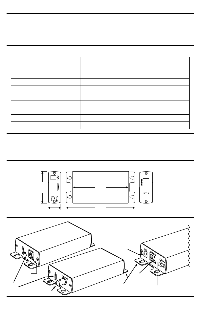
Overview:
BNC Connector
Tx/Rx
DIP Switch
Mounting tabs
(4 per unit)
RJ-45
Connector
5VDC
Connector
RJ-45
Connector
Status LEDs
(Power / RX / Link)
IPB-A1100Q
Rear
Dimensions
Front
(same for both models)
IPB-A1200Q
Rear
PB-A1100Q shown. Both models are the same size.
Front
Rear
Top
25/8”
67mm
11/16”
27mm
41/2”
115mm
511/16”
145mm
2 SECO-LARM U.S.A., Inc.
Page 3

ENFORCER IP / Ethernet Extenders
SECO-LARM U.S.A., Inc.
1. Determine the location where the units will be placed as well as how much cable will be required.
2. If desired, use the included screws to mount the receiver and transmitter to a wall or other surface.
Use the mounting tabs found on the corners of the enclosure.
3. On one unit, switch the Tx/Rx DIP switch to “Tx”. This is now the transmitter.
4. Connect the transmitter to an IP camera or other TCP/IP output device using Cat5e/6 cable.
Connect via the Ethernet port found on the front of the Active IP Balun.
5. On the second unit, switch the Tx/Rx DIP switch to “Rx”. This is now the receiver.
6. Connect the receiver to a DVR, PC or other TCP/IP receiving device using Cat5e/6 cable.
Connect via the Ethernet port found on the front of the Active IP Balun.
7. Run a cable between the two units and connect them via the rear-panel connectors.
Use Cat5e/6 cable for the IPB-A1100Q. Use coaxial cable for the IPB-A1200Q.
8. Connect one 5VDC adapter to the transmitter and another to the receiver.
9. Switch on the IP source (i.e. CCTV camera) and verify that the system is functioning properly.
Installation:
IPB-A1200Q
Up to 5,900’
(1,800m) of coaxial
IP Camera
PC or DVR
Sample Application:
Tx/Rx DIP Switch Positions
The unit is a
transmitter
The unit is a
receiver
Each unit can act either as
a transmitter (Tx) or a
receiver (Rx). To set the
function of a unit, simply
set the DIP switch located
on the rear of the unit to
the desired position.
Rear panel connections
IPB-A1100Q
Set Tx/Rx DIP Switch
Connect Cat5e/6 cable between
the receiver and transmitter
Front panel connections
Both models
Connect 5VDC Adapter
Connect Cat5e/6 cable to a TCP/IP device.
IPB-A1100Q
Up to 3,900’
(1,200m) of Cat5e/6
IP Camera
PC or DVR
Rear panel connections
IPB-A1200Q
Set Tx/Rx DIP Switch
Connect coax cable between
the receiver and transmitter
3
Page 4

ENFORCER IP / Ethernet Extenders
Troubleshooting
IP device does not function correctly
Make sure the balun is powered on both sides.
Make sure the IP source and DVR or PC are powered.
Test the coaxial or Cat5e/6 cable between the receiver
and transmitter and make sure it is functional.
Make sure that there are no problems with the IP device,
cables, or DVR by plugging the IP device directly into the
DVR or PC using the Cat5e/6 cables.
Make sure that the Tx/Rx DIP switches are in the
correct position for each unit (see page 3 for details).
Make sure that the cable does not exceed the
maximum distance (see page 2 for more details).
Products Available from SECO-LARM:
WARRANTY This SECO-LARM product is warranted against defects in material and workmanship while used in normal
service for a period of one (1) year from the date of sale to the original consumer customer. SECO-LARM’s obligation is
limited to the repair or replacement of any defective part if the unit is returned, transportation prepaid, to SECO-LARM.
This Warranty is void if damage is caused by or attributed to acts of God, physical or electrical misuse or abuse, neglect,
repair, or alteration, improper or abnormal usage, or faulty installation, or if for any other reason SECO-LARM determines
that such equipment is not operating properly as a result of causes other than defects in material and workmanship.
The sole obligation of SECO-LARM, and the purchaser’s exclusive remedy, shall be limited to replacement or repair only, at
SECO-LARM’s option. In no event shall SECO-LARM be liable for any special, collateral, incidental, or consequential
personal or property damages of any kind to the purchaser or anyone else.
NOTICE: The information and specifications printed in this manual are current at the time of publication. However, the
SECO-LARM policy is one of continual development and improvement. For this reason, SECO-LARM reserves the right
to change specifications without notice. SECO-LARM is also not responsible for misprints or typographical errors.
Copyright © 2010 SECO-LARM U.S.A., Inc. All rights reserved. This material may not be reproduced or copied, in
whole or in part, without the written permission of SECO-LARM.
SECO-LARM
®
U.S.A., Inc.
16842 Millikan Avenue, Irvine, CA 92606 Website: www.seco-larm.com
Tel: 800-662-0800 / 949-261-2999 Fax: 949-261-7326 E-mail: sales@seco-larm.com
MiPB-A1x00Q_1012.docx
PITSW4
VGA over Cat5e/6
Passive Video Baluns
Active Balun Hub
Voltage Converters
and Boosters
CCTV Power Supplies
Rack Mount
Power Supply
4 SECO-LARM U.S.A., Inc.
 Loading...