

Page 1
ENFORCER ACTIVE VIDEO BALUN
Installation Manual
TROUBLE SHOOTING
Problem
Wavy or ghost image if
connected to image
processor (e.g.,
multiplexer or DVR), but
not if directly to monitor?
Image background flutters
b
etween dark and light?
Image is wavy and shakes?
Image is weak or faded?
No image?
Poor image quality when
testing using cable on a
reel?
Possible Cause
a. Strong electromagnetic interference.
b. Poor signal, or balun separation is
too long.
c. Split pairs.
d. Crimped cable.
Interference from external power source.
Twisted pair wires reversed.
a. Exceeded recommended balun
separation.
b. Using lower-grade cable than
recommended.
a. Power is off.
b. Cable is incorrectly connected/crimped.
c. Cable was accidentally cut.
d. Wires running from pins 7 and 8
reversed.
e. Defective camera or remote video
device.
f. Defective video balun.
Induction from the coiled cable.
Possible Solution
a. Move the cable away from possible sources of
interference.
b. Install video amplifier between image processor and balun.
c. Ensure same twisted pair connects to balun at both ends of
cable.
d. Replace cable with new cable.
Remove power source, or adjust monitor's brightness and
contrast.
Try reversing polarity of the 2 wires at one end of cable.
a. Reduce cable length.
b. Replace with a higher-grade cable. Cat 5e cable meets
specifications in the manual. Cat 5e or better cable
allows longer range.
a. Check the power supplies of all devices connected to
the cable.
b. Check video signal of receiver.
c. Double-check that the cable was connected and
crimped properly.
d. Run a continuity test on all wires in the cable.
e. Reverse the wires.
f. Replace the unit with a new unit.
Test only with cable laid out in such a way that it is not
coiled and does not double back on itself.
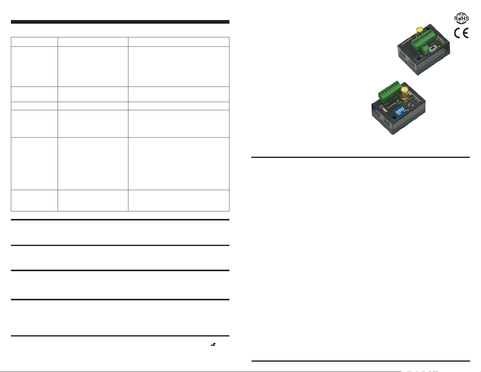
®
ENFORCER
EVT-TB1-42TQ
EVT-TB1-42TAQ*
Active Video Balun – Transmitter
EVT-RB1-4T2Q
EVT-RB1-4T2AQ*
Active Video Balun – Receiver
EVT-AB1Q
EVT-AB1AQ*
Transmitter and Receiver set
EVT-RB1-4T2Q
Receiver
*EVT-TB1-42TAQ, EVT-RB1-4T2AQ, EVT-AB1AQ models does not include power adapter.
WHAT IT IS
The ENFORCER’s Active Video Baluns are the quick, low-cost way to connect CCTV cameras to a monitor,
multiplexer, or video recorder at up to 1.5 miles (2,400 meters) away for monochrome cameras, or up to 1
mile (1,500 meters) away for color cameras.
The baluns allow a CCTV camera’s video signal to be transmitted over low-cost Cat 5e unshielded twisted pair
(UTP) cable instead of costly coax cable. They are suitable for full-motion color and monochrome cameras.
EVT-TB1-42TQ
Transmitter
IMPORTANT:
state, and local laws and statutes related to monitoring and recording audio and video signals. SECO-LARM will not be held
responsible for the use of this product in violation of any current laws or statutes.
WARNING:
electric shock, damage the device, and void the warranty. Do not open the case of this device, as there are no fieldserviceable components inside.
WARRANTY:
service for a period of three (3) years from the date of sale to the original consumer customer. Our obligation is limited to the
repair or replacement of any defective part if the unit is returned, transportation prepaid, to SECO-LARM. For complete
details regarding the SECO-LARM warranty, please contact SECO-LARM.
NOTICE:
SECO-LARM policy is one of continual development and improvement. For this reason, SECO-LARM reserves the right to
change specifications without notice. SECO-LARM is also not responsible for misprints or typographical errors.
Copyright © 2013 SECO-LARM U.S.A., Inc. All rights reserved. This material may not be reproduced or copied, in whole or in
part, without the written permission of SECO-LARM.
SECO-LARMSECO-LARM
SECO-LARM
SECO-LARMSECO-LARM
16842 Millikan Avenue, Irvine, CA 92606
Tel: 800-662-0800 / 949-261-2999 Fax: 949-261-7326
Users and installers of this product are responsible for ensuring this product complies with all national,
Incorrect mounting which leads to exposure to rain or moisture inside the enclosure could cause a dangerous
This SECO-LARM product is warranted against defects in material and workmanship while used in normal
The information and specifications printed in this manual are current at the time of publication. However, the
®
U.S.A., Inc. U.S.A., Inc.
U.S.A., Inc.
U.S.A., Inc. U.S.A., Inc.
Website: www.seco-larm.com
E-mail: sales
@
seco-larm.com
MiEVTAB1Q_1304.pmd
PITSW4
Page 8
FEATURES
!
Active operation – The transmitter amplifies the video signal for excellent picture quality at long distances.
!
Transmits video signal up to 8,000 ft. (2.4km) for B/W and 5,300 ft.(1.5km) for color.
!
Also transmits either PTZ (pan/tilt/zoom) data or low voltage (12-14 VAC/VDC) to CCTV cameras.
!
Uses low-cost Cat 5e unshielded twisted pair cable instead of costly coaxial cable.
!
Includes BNC connectors and removable terminal blocks
– No need to waste time crimping RJ-45 connectors.
!
High immunity from interference
– Built-in impedance coupled device and noise filter.
!
Easy installation. Removable terminal blocks.
!
Transmitter has DC output for remote CCTV cameras or peripherals.
!
Power can also be sent from a central location to remote sites using the transmitter and receiver.
!
Includes 12VDC power adapters.
!
Gold-plated BNC connectors.
!
Surge protection on video signal. Ground lifting and transient protection.
Note: Model numbers that ends with "Q" represents RoHS compliant products.
Page 2
ENFORCER ACTIVE VIDEO BALUNENFORCER ACTIVE VIDEO BALUN
(--)
(
+
)
Camera
12 VDC
adapter
500mA
DC Output, max. 460mA using
the included 500mA DC adapter.
Must adjust DC power to
compensate the voltage drop.
EVA-F5521-3
Cat 5e
Dimensions:
(Transmitter & receiver are the same size.)
2.3” (59mm)
1.7” (43mm)
(41mm)
1.6”
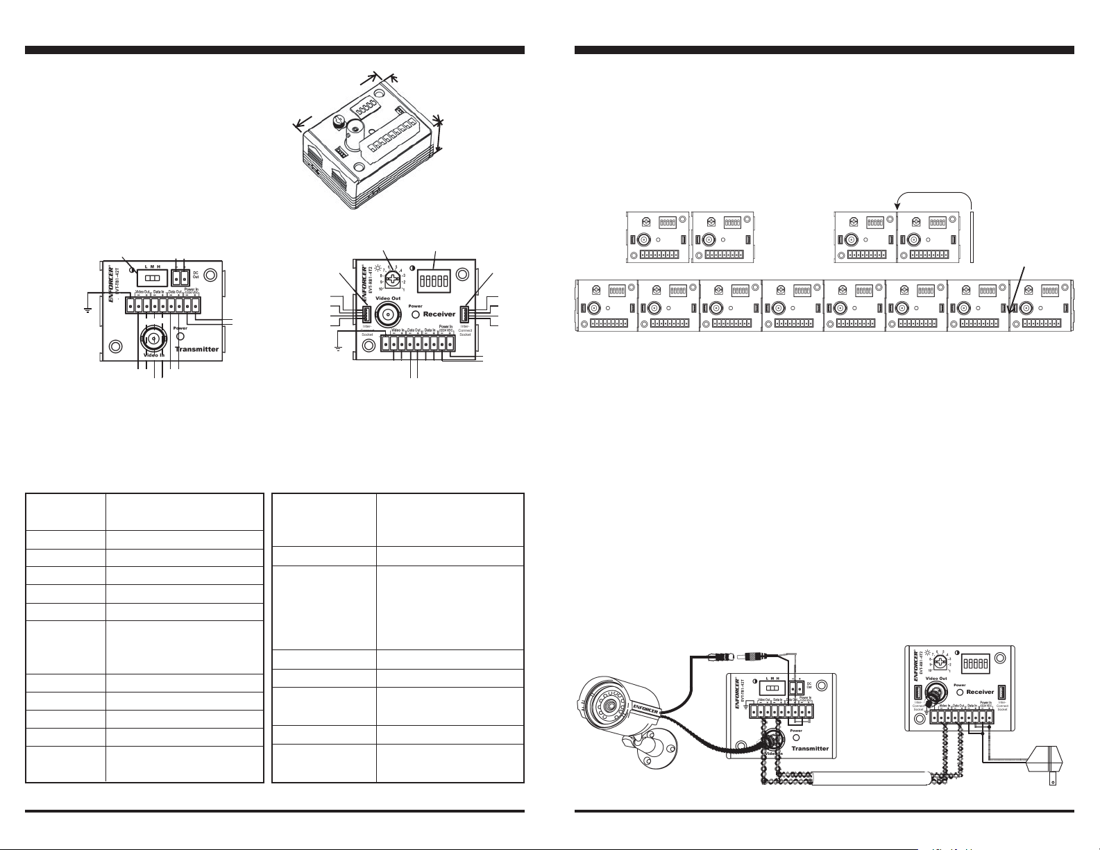
MOUNTING AND DAISY-CHAINING MULTIPLE RECEIVERS (optional) (fig. 4):
The optional EVT-xxxx 1U balun mounting plate allows up to eight EVT-RB1-4T2Q receivers to be mounted on
a standard 19-inch rack along with other video equipment for a safe and secure installation.
The receivers can be daisy-chained together for easier mounting of multiple units and to reduce the number
of power supplies, using the included patch cords with a 4-pin connector on each end.
Receiver
Wiring:
Transmitter:
Gain
Adjustment
LMH
++
+
-
++
Video out
Data in
Note 1: Output depends on adapter used. The transmitter uses 40mA. So a 12VDC, 500mA adapter gives 12VDC, 460mA through
this output, or a 24VDC, 500mA adapter gives 24VDC, 460mA through this output.
IMPORTIMPORT
ANTANT
: T: T
IMPORT
IMPORTIMPORT
est output before connecting to camera or other device.est output before connecting to camera or other device.
ANT
: T
est output before connecting to camera or other device.
ANTANT
: T: T
est output before connecting to camera or other device.est output before connecting to camera or other device.
Note 2: Can also be used to transfer 12~24 VAC/VDC. See fig. 5.
1
DC out
++
-
+
++
++
+
++
Power in
-
++
-
+
++
2
Data out
++
+
-
++
2
Receiver:
Inter-
connect
socket
Data
-
++
Data
+
++
Power
-
++
Power
+
++
Brightness
Adjustment
Video in
Shown
++
-
+
++
Data out
++
-
+
++
Gain
Adjustment
++
-
+
++
Data in
2
Inter-
connect
socket
++
+
++
Power in
-
2
(Reverse
Polarity
Sensitive)
Data
Data
Power
Power
-
++
+
++
-
++
+
++
For a clean installation, the receivers can be interlocked with each other.
Fig 4:
Step 1:
Lock
together
C
C
Step 2:
Add
”
ENFORCER
shim
C
“
C
C
Step 3:
ENFORCER
Add jumper.
®
®®
®®
Max 8 per
500mA adapter
C
C
Note 1: Interlocking design for cleaner and more professional results.
Note 2: Maximum of 8 can be interlocked per one 500mA adapter.
INSTALLATION OF MULTIPLE CAMERAS
Standard Cat 5e UTP cable includes four pairs of colored wires. Up to four CCTV cameras can be connected per
single run of Cat 5e UTP cable without interfering with each other under normal conditions.
However, for installations where multiple cameras cannot be run over the same cable, separate cables must
be run between the cameras and the remote devices.
Specifications for Transmitter & Receiver:
Range Color 5,000’ (1,524m)
B/W 8,000’ (2,438m)
Video format RS170, NTSC, PAL, SECAM, CCIR
Video input 1Vp-p, 75 ohms, BNC connector
Data/Aux RS422/RS485, or 12/24 AC/DC
Cable type Cat 2 or better (best if Cat 5e)
Blue LED Power on/off
Adjustments Tx - 3 positions
Rx - 5 dip switches
(32 combinations - ref. pg. 6)
Insertion loss
Return loss
Freq. response DC ~ 5MHz
Attenuation DC ~ 5MHz, 1.5dB max.
< 2dB per pair from DC ~ 5MHz
>15dB from DC ~ 5MHz
Common mode 60dB
rejection
1
Shorter range may result when Baluns are used with DVR. 2Can also be used to transmit low-voltage (12~24) AC/DC. Fig. 5
Page 2 Page 7
1
1
2
Power 12/24 VDC. 12VDC adapter
included (can accept either
regulated or unregulated).
Power consumption 40mA Tx, 60mA Rx @ 12VDC
Surge protection
(video)
Surge ratings IPP: 100 Amp at
10µsec. x 1000µsec. Max peak
current: 250 Amp at 8µsec. x
20
µ
sec., transient voltage
surge suppressors
Temperature range 7°~329° F (-14°~165° C)
Humidity range 0~95%
Impedance (BNC): 75Ω
(terminal): 100Ω
Case ABS plastic
Wt. (
without adaptors
) Tx: 3.4 oz. (95g)
Rx: 3.0 oz. (84g)
OTHER CABLE TYPES
The active video baluns, when used with Cat 5e UTP cable, offer the performance characteristics mentioned in
this manual. Other types of twisted cable can be used as well. However, the performance characteristics vary
from cable to cable, and so care must be taken when using other types of cable. Specifically, the maximum
distance between the camera and the remote device may decrease significantly with lower grades of cable.
Fig. 5:
Using active balun to send video and low-voltage power.
EVA-F5521-3Q
Page 3

NOTE: This connection is only for cameras which have an optional PTZ controller.
Video In (two terminals) – Connect to the Video Out output of the EVT-TB1-42TQ transmitter via one of the
4.
wire pairs in the UTP cable.
NOTE:The “+” and “-“ terminals are connected to the same “+” and “-“ terminals on the
EVT-TB1-42TQ transmitter.
5.
Video Out (BNC connector) – Plug to the Video In BNC connector on the central video control panel or the
active or passive hub.
D. Power up the camera, remote video device, and active baluns
NOTE: When the baluns are powered up, each unit’s red LED will turn steady on.
E. Adjust the EVT-TB1-42TQ transmitter (table 1):
ENFORCER ACTIVE VIDEO BALUNENFORCER ACTIVE VIDEO BALUN
Fig. 1: Use the EVT-series active video baluns as part of a complete video security
installation.
Up To 3,000 ft. (915m)
EVT-PB1Q
Passive video balun
C
EV-1323C12DW
C
DVR or Multiplexer
Table 1: Transmitter
Gain Settings
Low (L
Medium (M
High (H
)
)
)
Range
0 - 2,000 ft.
2,000 - 3,500 ft.
3,500 - 5,000 ft.
Move the slide switch to L (low), M (medium), or H (high) for best video quality.
F. Adjust the EVT-RB1-4T2Q receiver (table 2):
1. Adjust the receiver’s gain via the DIP switch according to the distance from the receiver to the
transmitter (see table 2).
2. Turn the brightness pod right or left while watching the video monitor to adjust the video image’s
brightness.
Table 2: Receiver
Range
0-1,000 ft.*
Dip Switch
Dip Switch #1
Dip Switch #2
Dip Switch #3
Dip Switch #4
Dip Switch #5
ONON
ON
ONON
OFF
OFF
OFF
OFF
1,000-1,500 ft.
ONON
ON
ONON
OFF
OFF
OFF
OFF
1,500-2,000 ft.
OFF
ONON
ON
ONON
OFF
OFF
OFF
2,000-2,500 ft.
ONON
ON
ONON
ONON
ON
ONON
OFF
OFF
OFF
2,500-3,000 ft.
ONON
ON
ONON
OFF
ONON
ON
ONON
OFF
OFF
3,000-3,500 ft.
OFF
ONON
ON
ONON
ONON
ON
ONON
OFF
OFF
3,500-4,000 ft.
OFF
OFF
OFF
ONON
ON
ONON
OFF
4,000-4,500 ft.
OFF
ONON
ON
ONON
OFF
ONON
ON
ONON
OFF
4,500-5,000 ft.
OFF
OFF
OFF
OFF
ONON
ON
ONON
PTZ
camera
EV-1323C12DW
Power
PTZ
camera
Power
Video
Data
Data
Video
Up To 3,000 ft. (915m)
EVT-PB1-31T
Passive Video Balun
with video, power,
and data.
(Coming soon)
Up To 3,000 ft. (915m)
EVT-PBM-V17
Modular snap-in passive video
balun (Use any standard wall
plate, eg., Leviton, ICC).
Up To 3,000 ft. (915m)
EVT-TB1-42TQ
Active video balun
(transmitter)
C
*If less than 1,000 ft., SECO-LARM recommends using EVT-PB1Q passive video balun.
Page 3Page 6
Page 4

ENFORCER ACTIVE VIDEO BALUNENFORCER ACTIVE VIDEO BALUN
(--)
(
+
)
Data
Camera
PTZ device
12 VDC
adapter
500mA
12 VDC
adapter
500mA
PTZ data
controller
Remote video
device (e.g., DVR)
Video
input
(BNC)
DC Output, max. 460mA using
the included 500mA DC adapter.
Cat 5e
Pigtail EVA-F55213
Cat 5e
INSTALLATION
Active video baluns are connected in pairs. The EVT-TB1-42TQ transmitter connects to the CCTV camera’s BNC
connector, and the EVT-RB1-4T2Q receiver connects to the BNC connector of a remote video device, such as a
monitor, digital video recorder, or video hub. Exception: The EVT-TB1-42TQ transmitter can be connected to
Fig 3:
Wiring the transmitter
and receiver with optional
data connection
EVA-F5521-3Q
passive video hubs like SECO-LARM’s 16-port EVT-PH16-4T2Q without the use of the EVT-RB1-4T2Q receiver,
but range will be significantly decreased.
A. Run the cable (fig. 2):
1. Make sure the distance between the CCTV camera and the remote video monitor, recorder, multiplexer,
or other device to which it is connected does not exceed the active balun’s range.
2. Run the UTP cable from the remote video device to where it will be connected to the CCTV camera.
Follow the CCTV camera’s installation instructions for information on how to safely run and hide this cable.
NOTE:
The ends of the cable near the CCTV camera and the remote video device should be bare wires. Do
not crimp to RJ-45
connectors.
Interlocking design for
Fig 2:
Typical installations
When using
multiple baluns,
only a jumper
(included) is
needed to extend
power & data
(max of 8 per
Pigtail-EVA-F5521-3Q
DC Output, max. 460mA
using the included 500mA
DC adapter.
12/24
VDC
Up to 1.5 miles (2.4 km)
B. Wire the EVT-TB1-42TQ transmitter (fig. 3):
power adapter).
Cat 5e
12/24 VDC
1. Power In (two terminals) – Connect to the included 12VDC adapter.
NOTE: This connection is polarity-sensitive. Connect “+” terminal to +12VDC, “-“ terminal to ground.
2. Data In (two terminals) – Connect to the pan/tilt/zoom (PTZ) output from the remote video device via
one of the wire pairs in the UTP cable coming from the EVT-RB1-4T2Q receiver.
NOTE: The “+” and “-“ terminals must be connected to the same “+” and “-“ terminals on the
EVT-RB1-4T2Q receiver.
NOTE: This connection is only for cameras which have an optional PTZ controller.
Page 4 Page 5
cleaner & more
professional installs
C
C
C
Multiplexorer or DVR
Monitor
3. Data Out (two terminals) – Connect to the PTZ input of the video camera mounting device to operate
the PTZ controls.
NOTE: This connection is only for cameras which have an optional PTZ controller.
Video Out (two terminals) – Connect to the Video In input of the EVT-RB1-4T2Q receiver via one of the
4.
wire pairs in the UTP cable.
NOTE: The “+” and “-“ terminals are connected to the same “+” and “-“ terminals on the
EVT-RB1-4T2Q receiver.
NOTE:
When connecting to a passive or active video hub, connect these wires to the hub’s Video In inputs.
5. P
ower Out (two terminals) – If needed, can be used to power a CCTV camera or other device, eliminating
the need for a separate power supply. Current available is the current output of the DC adapter, less
40mA. So, if a 12VDC, 500mA adapter is used, power out is 12VDC, 460mA, or if a 24VDC, 500mA
adapter is used, power out is 24VDC, 460mA. Test output before connecting the camera or device.
6. Video In (BNC connector) – Plug the camera’s BNC connector to this connector.
C. Wire the EVT-RB1-4T2Q receiver (fig. 3):
1. Power In (two terminals) – Connect to the included 12VDC adapter.
NOTE: This connection is polarity-sensitive. Connect “+” terminal to +12VDC, “-“ terminal to ground.
2. Data Out (two terminals) – Connect to the Data In terminals of the EVT-TB1-42TQ transmitter.
NOTE: This connection is only for cameras which have an optional PTZ controller.
NOTE: The “+” and “-“ terminals are connected to the same “+” and “-“ terminals on the
EVT-TB1-42TQ transmitter.
3. Data In (two terminals) – Connect to the PTZ output of a central video control panel or passive or
active video hub.
 Loading...