

SECO-LARM EVP-1SD4B9ULQ, EVP-1SD6P16UL, EVP-1SD4P9UL, EVP-1SD2B4ULQ, EVP-1SD6BHULQ Installation Manual
Page 1
BEFORE CONNECTING TO CCTV CAMERAS OR DEVICES:
• Check the DIP switch setting to ensure correct voltage (6VDC, 12VDC, or 24VDC).
• With power turned on, check the wires connected to each terminal pair to ensure correct voltage.
Installation Manual
®
ENF ORCER
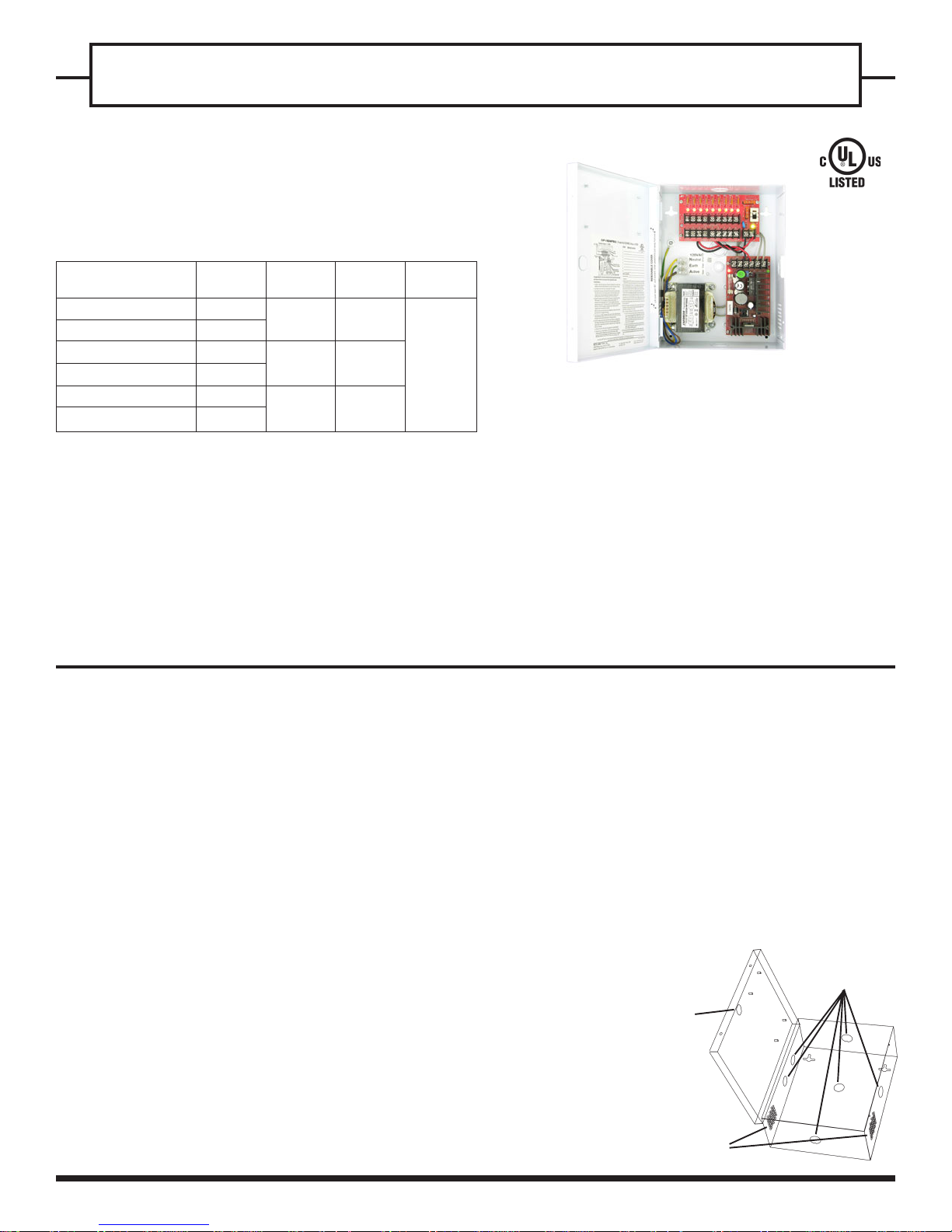
DC Power Supplies for CCTV Cameras and Accessories
AUDIO/VIDEO APPARATUS
26BZ
Model No.
EVP-1SD2P4UL
EVP-1SD2B4ULQ
EVP-1SD4P9UL
EVP-1SD4B9ULQ
EVP-1SD6P16UL
EVP-1SD6BHULQ
Type of
output fuse
PTC*
Blade
PTC*
Blade
PTC*
Blade
Total supply
Current
2A
4A
6A
No. of
output
4
9
16
Output
Voltage (VDC)
6/12/24
*Positive Temperature Coefficient
Specifications:
!
Adjustable VDC outputs:
•
Output voltage adjustable with potentiometer to
compensate for voltage drop
•
Each output individually fused
•
Output fuses rated 1.1A for PTC and 1A for blade fuse
•
Individual red status indicator LED for each output
•
Main power switch to turn on/off power to outputs
What it is:
This ENFORCER CCTV power supply centralizes the CCTV system's power
input, power transformer, DC regulator, and independently-fused power
outputs in one heavy-duty, easy-to-install enclosure.
Note before installation:
• DOUBLE-CHECK VOLTAGE SETTINGS BEFORE CONNECTING THE CAMERAS.
• Indoor use only - Do not mount where exposed to rain or moisture.
• For professional installation only.
• Installation must conform to all local codes.
Installation:
1. Find a good location. Mount the enclosure out of sight and protected from
moisture, but where an authorized service person can have access.
NOTE: Make sure the space where the enclosure is to be mounted has
adequate ventilation. Otherwise, heat buildup inside the enclosure could
damage the electronic parts or cause the PTC fuses to trip needlessly.
2. Locate the enclosure mounting holes. Using the enclosure as a template,*
mark the location of one of the two upper screws on the wall with a pencil.
Fasten one 5/32" x 1" (4 x 26mm) screw (not included) until the gap
between the wall and the screw head is approximately 1/4" (6mm).
Hang the enclosure on this screw and adjust the proper angle of the
enclosure. Repeat with the second screw. Then mark up and securely
fasten the enclosure with all four screws.
*Or mark up a paper template from the enclosure and drill after taping the
template in correct position.
EVP-1SD4P9UL Shown
!
Power:
•
Input: 120VAC, 60Hz ; Output: 6/12/24VDC
•
Main fuse rated 5.0 Amps @ 250VAC ( 3.0 Amps for
EVP-1SD2x4UL)
•
On board spare fuse and 6-foot power cord included
!
Enclosure:
•
Heavy-duty steel case to protect the power connections
•
Removable steel cover for easy access
•
Ventilation holes to prevent heat build-up
•
Dimensions - 10” x 7.75” x 3.5” (254 x 196 x 89 mm)
[12.15" x 12.25" x 3.6" (308 x 311 x 91 mm) for
EVP-1SD6P16UL / EVP-1SD6BHULQ]
•
Knock-out on the cover for optional cam lock
3. Determine how the main power line and CCTV camera cables will be run -The enclosure has knock-outs on the side, top, bottom, and rear panels for
running cables. Punch the appropriate knock-outs. See Fig. 1.
NOTE:
an electrical conduit of not more than 1" outside diameter. Wires running
inside the electrical conduit must not be too tight.
4. To connect the main power cord to the small white terminal block, follow
the wire color indicated on the "NEA" label that is placed beside the
terminal block (i.e., white wire on top, green wire to the middle, and black
wire to the bottom of the terminal block, see Fig. 2).
Use the provided nut and cable clamp to fasten the power cord onto the
metal enclosure in the location shown on Fig. 2 if necessary. A plastic
snap bushing is also provided for the power cord hole.
If cables are run out of the side, top, or bottom panels,
FIG. 1: Knockouts
for running cables
Knock-out for
optional cam lock
Ventilation
Holes
protect with
Cable & Power
Knock-outs
Page 2
CCTV DC Power Supply Installation Manual
5. Connect the power input wires of the CCTV cameras or accessories to the
PCB marked 173-001 (see Fig. 2). Observe correct polarity. The terminals
marked “P” are for positive wires, and “N” are for negative wires. Each
output consists of one “P” terminal and one “N” terminal.
Run wire pairs from the terminals through or along the wall to where the
CCTV cameras and/or accessories are mounted.
NOTE: Use minimum 18-gauge wires to minimize voltage drop.
NOTE:
Test each wire pair's voltage before connecting to cameras.
6. Turn the main switch ON. The green LED on the 173-001 PCB will light to
show that power is present. The red LEDs on the printed circuit board will
light to show each terminal pair is working correctly.
7. Test the voltage output at the end of each wire pair to see if there is any
significant voltage drop. The voltage output for all wire pairs should be
about the same unless a voltage drop occurred on a certain wire pair.
When running wires from the DC power supply, voltage drop can occur for
one of three reasons:
a. The wire is too thin. Use minimum 18-gauge wire.
b. The wire has run a long distance. If a wire pair is showing significant
voltage drop compared to the others, either shorten the length of the
voltage drop affected wire pair, or lengthen the other wire pairs to
have a similar voltage output reading on all wire pairs.
c. A large number of CCTV cameras and/or accessories connected to the
173-001 PCB is causing excessive power drain across all the outputs.
8.
Adjust the voltage output if needed - If the voltage output reading at the end
of the wire pair where it is connected to the camera or accessory
falls
below the minimum voltage required, use a screwdriver to carefully turn
the potentiometer located on the ST-2406 PCB. (See Fig. 2 and Table 1.)
This will increase the total voltage output from the 173-001 PCB to
compensate for the voltage drop.
NOTE: Adjusting the potentiometer affects the voltage output of all the
wire pairs. Using a voltage output in excess of the specified voltage level
of a camera may cause damage.
9. After all adjustments, turn the main switch OFF.
10. Connect all the wire pairs to their respective CCTV cameras or
accessories.
Double-check the specified operating voltage of each before
connecting it to the device.
NOTE:
a. Connect a maximum of four devices (EVP-1SD2x4UL), nine devices
(EVP-1SD4x9UL), or 16 devices (EVP-1SD6P16UL/EVP-1SD6BHULQ).
b. The CCTV cameras and accessories connected to the printed circuit
board must all operate on the same voltage (6VDC, 12VDC, or 24VDC).
c. The power supply is preset at 12VDC output. For 6VDC or 24VDC
operation, adjust the DIP switch (see Fig. 2 and Table 1).
d. Maximum total current connected to all terminals must not exceed the
power supply's total current capacity, see Table 2 below.
11. Turn the main switch ON.
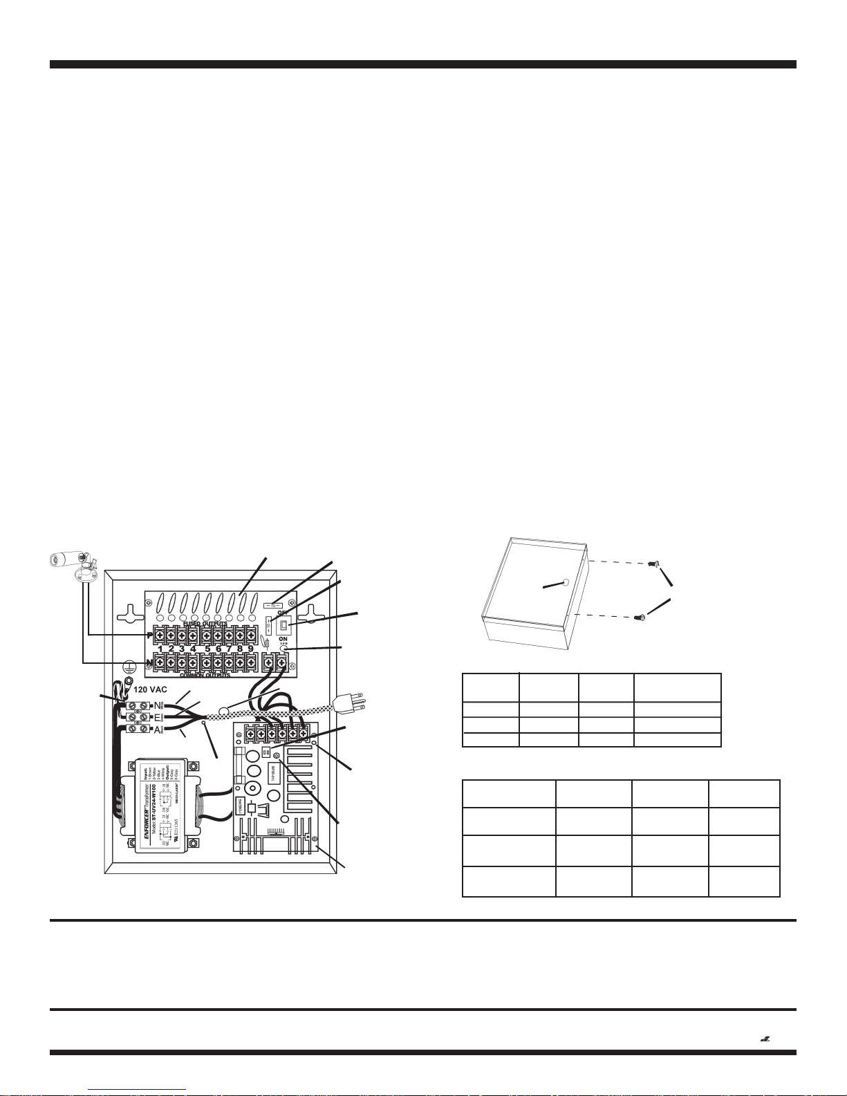
12. Close the steel door of the enclosure and secure it with either the provided
machine screws or an optional cam lock (see fig. 3).
FIG. 3: Securing the Enclosure:
Close the cover, then secure with included machine screws or optional cam lock.
FIG. 2: Power Connections
ENFORCER
Example: Output 1, 12VDC
173-001 PCB
Spare Fuse
Main Fuse
Main
Cam Lock
(optional)
Machine
Screws
(included)
Switch
Green LED
(Power Indicator)
AC
Terminal
Block
White wire
Green wire
Power cord
hole
Dip Switch for
Black wire
cable
clamp
use
volt. selector
6/12/24VDC
Green LED
(Power Indicator)
Potentiometer
to Adjust DC
Voltage range
ST-2406-5A PCB
EVP-1SD4P9UL Shown
The SECO-LARM® policy is one of continual development and improvement. For that reason, SECO-LARM reserves the right to change specifications without notice. SECO-LARM is not responsible for misprints.
Table 1: DC Voltage Output Dip Switch Settings
Voltage
6V
12V
24V
Dip SW1
ON
OFF
OFF
Dip SW2
OFF
OFF
ON
Voltage range
@ no load
5.9~8.9
12.4~14.7
27.6~30
Table 2: Max. supply current chart
Model
EVP-1SD2P4UL
EVP-1SD2B4ULQ
EVP-1SD4P9UL
EVP-1SD4B9ULQ
EVP-1SD6P16UL
EVP-1SD6BHULQ
Max. supply
current at 6VDC
2 Amp.
4 Amp.
6 Amp.
Max. supply
current at 12VDC
2 Amp.
4 Amp.
6 Amp.
Max. supply
current at 24VDC
1 Amp.
2 Amp.
3 Amp.
WARRANTY: This SECO-LARM product is warranted against defects in material and workmanship while used in normal service for a period of one (1) year from the date of sale
to the original consumer customer. SECO-LARM’s obligation is limited to the repair or replacement of any defective part if the unit is returned, transportation prepaid, to SECO-LARM.
This Warranty is void if damage is caused by or attributed to acts of God, physical or electrical misuse or abuse, neglect, repair, or alteration, improper or abnormal usage, or faulty
installation, or if for any other reason SECO-LARM determines that such equipment is not operating properly as a result of causes other than defects in material and workmanship.
The sole obligation of SECO-LARM, and the purchaser’s exclusive remedy, shall be limited to replacement or repair only, at SECO-LARM’s option. In no event shall SECO-LARM be liable
for any special, collateral, incidental, or consequential personal or property damages of any kind to the purchaser or anyone else.
SECO-LARMSECO-LARM
SECO-LARM
SECO-LARMSECO-LARM
Tel: 800-662-0800 / 949-261-2999 Fax: 949-261-7326
®
U.S.A., Inc., U.S.A., Inc.,
U.S.A., Inc., 16842 Millikan Avenue, Irvine, CA 92606
U.S.A., Inc., U.S.A., Inc.,
Website: www.seco-larm.com
E-mail: sales
Copyright 2009 SECO-LARM U.S.A., Inc. All rights reserved.
@
seco-larm.com
MiEvpDc120_0912.pmd
Order Part #764-011-4%
PITSW1
 Loading...