

Page 1
Note: Model numbers that end with “Q” or products that have a round green “Q” sticker signify RoHS compliance.
EV-7105-NPEQ (NTSC)
EV-7105-PPEQ (PAL)
Mini PTZ Camera
Manual
10x Optical zoom and 10x digital zoom
Up to 100x zoom
Up to 360°/sec pan/tilt motion
Outdoor or indoor use
Up to 127 preset target views, each
with its own characteristics such as
white balance and auto exposure
Up to 95° tilt, up to 180° with auto-flip
Page 2

ENFORCER Mini PTZ Camera
SECO-LARM, U.S.A., INC.
Introduction
2
SYSTEM INFORMATION Menu
18
Features and Functions
3
DISPLAY SETUP Menu
19
Parts List
4
SET NORTH DIRECTION Menu
19
Specifications
4
PRIVACY ZONE Menu
20
Dimensions
5
EDIT MASK Menu
20
Safeguards and Precautions
6
DOME CAMERA SETUP Menu
21
Overview
7
ZOOM CAMERA SETUP Menu
22
Communication Protocol and Camera ID
8
WB SETUP Menu (White Balance)
22
Installation
9
AE SETUP Menu (Auto Exposure)
23
Connecting Multiple PTZ Cameras
9
MOTION SETUP Menu
24
Pre-Operation Checklist
10
PARKING ACTION SETUP Menu
25
Understanding and Operating Preset and
Pattern Functions
11
PRESET Menu
26
Configuring Mini PTZ settings using an
ENFORCER DR-1 Series DVR
12
EDIT SCENE Menu
27
Reserved Presets
13
EDIT LABEL Menu
27
Configuration Defaults
13
SWING SETUP Menu
28
OSD Display of Main Screen
14
PATTERN SETUP Menu
29
OSD Main Screen
14
EDIT PATTERN Menu
29
Operating the OSD Menus
15
GROUP SETUP Menu
30
OSD (On-Screen Display) and
Programming Flowchart
16-17
EDIT GROUP Menu
30-31
SPEED DOME CAMERA Menu
18
SYSTEM INITIALIZE Menu
31
Introduction
The ENFORCER Mini PTZ Camera is a compact full-featured PTZ (pan/tilt/zoom) CCTV camera. In as little as one second,
the camera can pan a full 360 degrees, tilt up to 95 degrees under normal operation, or auto-flip 180 degrees. It also
features an optical zoom of up to 10X and a digital zoom of up to 10X, providing a clear view of the entire protected
premises. The 1/4-inch Interline Transfer CCD provides high-resolution, 520 TV line images in as little as 0.7 Lux for color use
and 0.02 Lux for black and white use. A wide range of mounting brackets and posts combined with a small size makes the
ENFORCER Mini PTZ Camera ideal for almost any installation.
Controlling the mini PTZ camera is done using a keyboard controller or DVR that uses RS-485 for communicating between
the devices.
Table of Contents
a
Table of Contents
Introduction
The EV-7105-NPE is a full-featured PTZ (pan/tilt/zoom) CCTV camera which can pan a full 360 degrees in as
little as a second or tilt up to 95 degrees under normal operation or as much as 180 degrees using auto-flip. It
also features an optical zoom of up to 10X and a digital zoom of up to 10X, providing a clear view of the entire
protected premises. The 1/4 inch Interline Transfer CCD provides high-resolution, 500 TV line images in as little
as 0.7 Lux for color use and 0.02 Lux for black and white use. A wide range of mounting brackets and posts
combined with the small size of the EV-7105-NPE make it an ideal PTZ camera for almost any installation.
Control of the EV-7105-NPE is done via a keyboard controller or DVR which uses Pelco protocols for
communicating between the devices. Non-Pelco-compatible devices will most likely not be able to operate the
EV-7105-NPE properly.
2
Page 3

ENFORCER Mini PTZ Camera
SECO-LARM, U.S.A., INC.
ENFORCER Mini PTZ Camera Features and Functions
Powerful and Flexible: The ENFORCER Mini PTZ Camera is equipped with a 1/4-inch CCD, a powerful Day and Night
function, up to 100x zoom (max. 10x optical zoom and 10x digital zoom), multiple focus modes, and other fully programmable
features.
Pan/Tilt Functionality: The camera features 360° endless pan motion and 95° tilt. It can be programmed to automatically
flip the image if it tilts under the unit. The pan/tilt function uses vector drive technology so that it quickly moves to the target
while ensuring the view on the monitor flows smoothly.
On-Screen Display (OSD): The On-Screen Display shows camera status and settings together with the preset target views.
A Wide Range of Programmable Options:
Up to 127 preset target views, each with its own characteristics such as white balance and auto exposure
Up to eight swing actions between two preset positions
Up to four patterns for moving the camera as if it were controlled by a joystick
Up to eight group actions, each including up to a total of 20 presets, swing actions, and patterns
Up to four privacy masks which can be increased or decreased in size to cover certain areas to
protect privacy
Reserved Presets: Certain camera characteristics can be specified by using reserved preset configurations instead of
individually configuring those characteristics.
Standard PTZ Control: Works with Pelco-D or Pelco-P compatible controllers via an RS-485 connection.
Smart Power-Up: Resumes the last action executed before power to the camera was cut, including most preset, pattern,
swing, and group actions.
Auto-Flip: Vertically inverts the image if the camera tilts below its center.
Parking Action: Should no operator-activated or automated camera action occur during a specified time (programmable
from 1 minute to 4 hours), the camera automatically moves to a pre-determined preset position or any pre-programmed
pattern, swing, or automatic camera function.
Privacy Zone Mask: Up to four privacy masks can be created to cover certain areas or objects such as windows or private
houses. The masks can be adjusted for size. When the camera moves past such areas or objects, the mask automatically
covers them.
Global or Local Image Setup: Determines how white balance and auto exposure settings are applied. When programmed
for "Global" setup, those settings are automatically applied to each preset location. Under "Local" setup, those settings are
set separately for each preset location. The "Global" settings for white balance and auto exposure will be used during jog
operations.
Semi/Auto Focus: The focus for each preset location is manually set, and the camera automatically uses that focus when it
moves to a preset location. During jog operations, the camera uses auto focus. The shift between semi-auto and auto focus
occurs automatically.
EV-7105-NPE PTZ Camera Features and Functions
Powerful yet flexible camera: 1/4-inch CCD camera with Day and Night function, up to 100X zoom (max. 10X
optical zoom and 10X digital zoom), multiple focus modes, and full programmability.
Powerful Pan/Tilt functionality: The camera features 360-degree pan motion, and it can be programmed to
automatically flip the image if it tilts under the unit. The pan/tilt function uses vector drive technology so that it
quickly moves to the target while ensuring the view on the monitor flows smoothly.
On-Screen Display (OSD) programming: The On-Screen Display shows camera status and settings together
with the preset target views.
Flexible programming capabilities:
Up to 127 preset target views, each with its own characteristics such as white balance and auto exposure.
Up to eight swing actions between two preset positions.
Up to four patterns for moving the camera as if it were controlled by a joystick.
Up to eight group actions, each including up to a total of 20 presets, swing actions, and patterns.
Up to four privacy masks which can be increased or decreased in size to cover certain areas to
protect privacy.
Reserved presets: Certain camera characteristics can be specified by using reserved preset configurations
instead of individually configuring those characteristics.
Standard PTZ control: Works with Pelco-D or Pelco-P compatible controllers via an RS-485 cable.
Power Up Action: Resumes the last action executed before power to the camera was cut, including most
preset, pattern, swing, and group actions, but not jog actions.
Auto Flip: Vertically inverts the image if the camera tilts
Parking Action: Should no operator-activated or automated camera action occur during a specified time
(programmable from 1 minute to 4 hours), the camera automatically moves to a pre-determined preset position.
Privacy Zone Mask: Up to four privacy masks can be created to cover certain areas or objects such as
windows or private houses. The masks can be adjusted for size. When the camera moves past such areas or
objects, the mask automatically follows them.
Global or Local Image Setup: Determines how white balance and auto exposure settings are applied. When
programmed for "Global" setup, those settings are automatically applied to each preset location. Under "Local"
setup, those settings are set separately for each preset location. The "Global" settings for white balance and
auto exposure will be used during jog operations.
Semi/Auto Focus: The focus for each preset location is manually set, and the camera automatically uses that
focus when it moves to a preset location. During job operations, the camera uses auto focus. The shift between
semi and auto focus occurs automatically.
3
Page 4

ENFORCER Mini PTZ Camera
SECO-LARM, U.S.A., INC.
Video Signal System
NTSC
PAL
Camera
CCD 1/4” Interline Tansfer CCD
Max. Pixels
811(H) x 508(V) 410K
795(H) x 596(V) 470K
Effective Pixels
768(H) x 494(V) 380K
752(H) x 582(V) 440K
Horizontal Resolution
500 TV Lines (Color), 570 TV Lines (B/W)
S/N Ration
50 dB (AGC Off)
Zoom
x 10 Optical Zoom, x 10 Digital Zoom
Focal Length
F1.8, f=3.8~38 mm
Min. Illumination
0.7 Lux (Color) / 0.02 Lux (B/W), 50 IRE
Day and Night
Auto / Day / Night (ICR)
Focus
Auto / Manual /SemiAuto
Iris
Auto / Manual
Shutter Speed
X128 ~ 1/120000sec
AGC
Normal / High / Off
White Balance
Auto /Manual (Red/Blue Gain Adjustable)
BLC
Low / Middle / High / Off
Flickerless
Selectable
SSNR
Low / Middle / High / Off
Pan/Tilt
Range
Pan: 360 degrees / second
Tilt: 180 degrees (Auto-Flip), 95 degrees (Normal)
Pan / Tilt Speed
Preset: 360 degrees / second
Manual: 0.05~360 degrees / second (proportional to zoom)
Swing: 1~180 degrees / second
Preset
127 Preset (Label, Camera Image Setting)
Pattern
4 Pattern, 1200 commands (about 5 minutes) / pattern
Swing
8 Swing
Group
8 Group (20 action entities / group)
Other Functions
Auto-Flip, Auto-Parking, Power Up Action, etc.
General
Communication
RS-485
Protocol
Pelco-D, Pelco-P selectable
Privacy Zone
4 Zone
Alarm Input
4 Input
OSD
Menu / PTZ Information, etc.
Rated Power
DC12V 2A
Dimension
Dome: ф100.5
Housing: ф141 x 140 (H) mm
Weight
About 1.2 Kg
Operating Temp.
0-40 degrees C (Indoor) -20-50 degrees C (Outdoor)
Range
Pan
360°
Tilt
180°
Pan/Tilt
Speed
Preset
Up to 360°/s (programmable)
Manual
0.05~360°/s (proportional to zoom)
Swing
1~180°/s
Presets
Max. 127 presets (Label, Camera Image Setting)
Patterns
Max. 4 patterns
Swings
Max. 8 swings
Groups
Max. 8 groups (20 actions/group)
Other functions
Auto-Flip, Auto-Parking, Power Up Action, etc.
Pan/Tilt:
Parts List:
1x Camera
1x Wall-mount bracket
1x Manual
4x Short screws (for attaching camera to bracket)
4x Long screws (for attaching bracket to wall)
1x Extension cord
EV-7105-NPEQ
EV-7105-PPEQ
Type
Mini PTZ Camera
Video output format
NTSC
PAL
CCD
1
/4” Interline Transfer
Resolution
Color: 520 TV Lines / B/W: 570 TV Lines
Pickup elements
768x494 pixels
752x582 pixels
Video output
1.0Vp-p composite video, 75Ω
Lens
F1.8, f=3.8~38mm
Minimum Illumination
Color: 0.7 Lux / B/W: 0.02 Lux
S/N Ratio
50dB (AGC OFF)
Zoom
x10 Optical / x10 Digital
Day and Night
Auto / Day / Night (ICR – removable IR cut filter)
Focus
Auto / Manual / Semi-Auto
Iris
Auto / Manual
Shutter Speed
1/60~1/120,000 s
AGC (Automatic Gain Control)
Normal / High / Off
Sense-Up
x2~x128
White Balance
Auto / Manual (Red, Blue, Gain Adjustable)
BLC (Back Light Compensation)
Low / Middle / High / Off
Flickerless
Selectable
SSNR (Noise Reduction)
Low / Middle / High / Off
Communication
RS-485
Protocol
Pelco-D, Pelco-P selectable
Privacy
4 Zones
OSD
Menu / PTZ information, etc.
Operating voltage
24VAC
Power consumption
20W
Operating temperature
Indoor: 32~104° F (0~40° C) /
Outdoor: -4~122° F (-20~50° C)
Dimensions
413/16” x7”x413/16” (122x180x122 mm)
Weight
2-lb 10-oz (1.2kg)
Specifications:
a
a
4
Page 5
ENFORCER Mini PTZ Camera
SECO-LARM, U.S.A., INC.
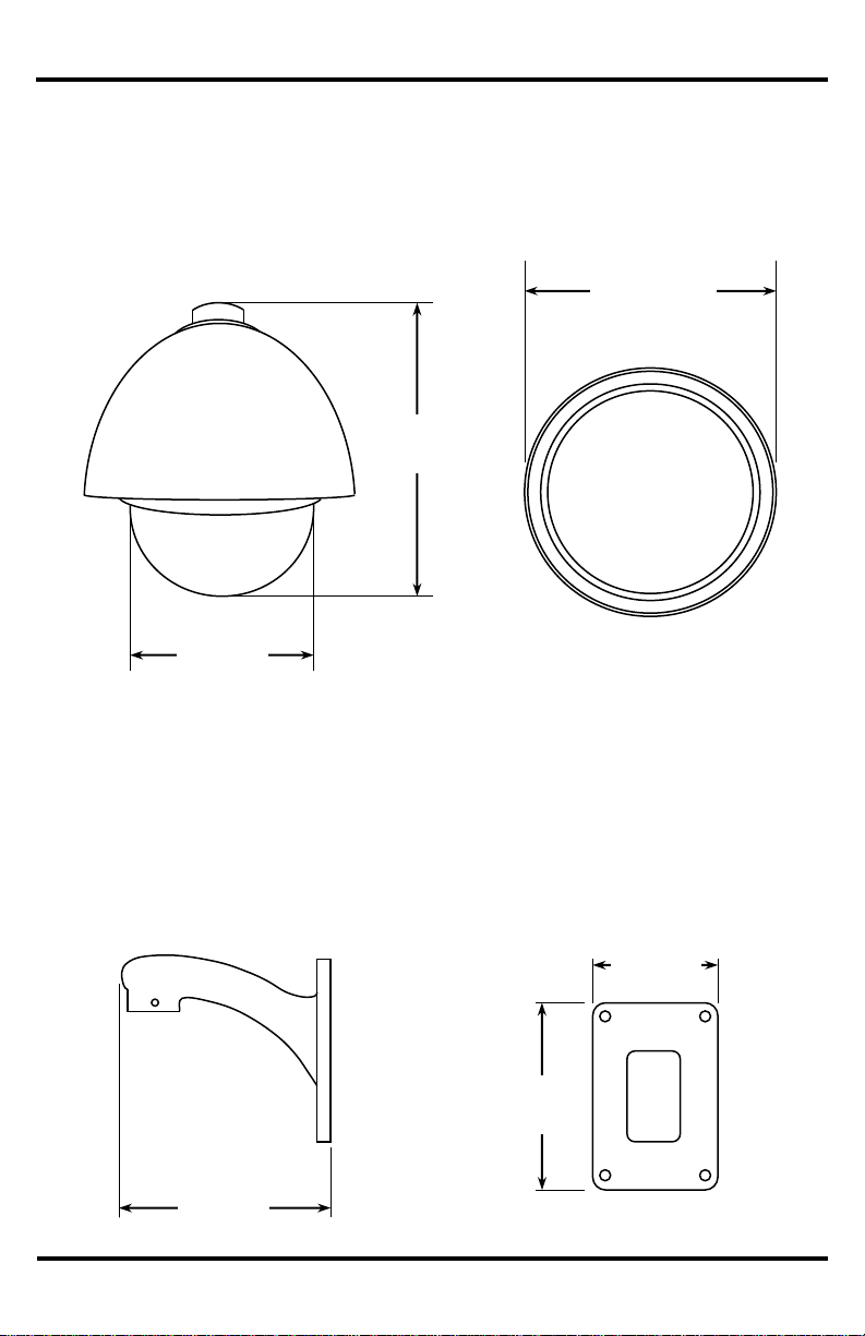
Dimensions:
Camera
Wall-Mount Bracket
7”
(180mm)
6”
(152mm)
31/8”
(80mm)
411/16”
(119mm)
61/2”
(166mm)
Side
Bottom
Side
Bottom
413/16”
(122mm)
5
Page 6

ENFORCER Mini PTZ Camera
SECO-LARM, U.S.A., INC.
Safeguards and Precautions
Before Starting:
1. Please read this manual carefully and keep it for future reference.
2. Use the camera within given temperature and electrical limits.
3. Do not point the camera at the sun. Heat could damage the camera, even when not in use.
4. Do not expose the camera to rain or moisture.
5. Do not install the camera in dusty or humid environments.
6. Do not mount the camera in areas exposed to radiation, strong magnetic fields, or strong electrical signals.
7. Do not open or disassemble the camera. There are no field-serviceable parts inside.
8. Do not drop the camera or subject it to strong vibrations.
9. This camera is VERY HEAVY. To prevent injury to the installer and client, do not mount it on an unstable or improperly
supported surface. When mounting, only use brackets or other mounting devices that are recommended in this manual.
Operation Precautions:
1. Only use regulated power supplies with voltage and minimum current output per the specifications of this camera.
2. If the camera gets hot or starts smoking while in use, disconnect the power immediately and contact the professional
installer or dealer.
Cleaning Precautions:
1. Periodically clean the dust off the entire camera with a slightly damp (NOT WET) cloth. DO NOT USE
chemical cleaners.
2. Do not move the camera while cleaning, as this could change the angle of the view.
3. If the dome cover becomes dusty, carefully clean using a slightly slightly damp (NOT WET) cloth. DO NOT USE
chemical cleaners. DO NOT SCRATCH the dome, as this will hurt the quality of the video image.
6
Page 7
ENFORCER Mini PTZ Camera
SECO-LARM, U.S.A., INC.
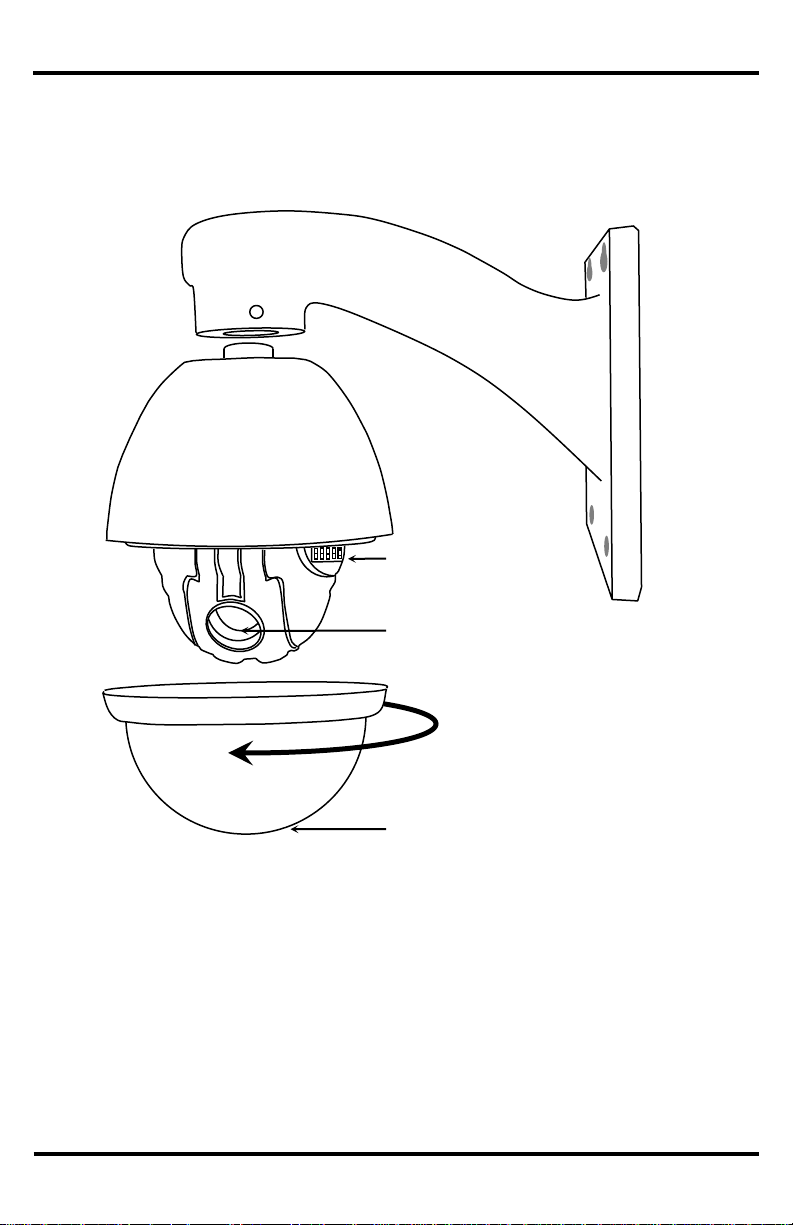
Wall mount
bracket
Camera
DIP switches
Lens
Dome
Turn counter-clockwise
to remove
Overview
a
7
Page 8
ENFORCER Mini PTZ Camera
SECO-LARM, U.S.A., INC.
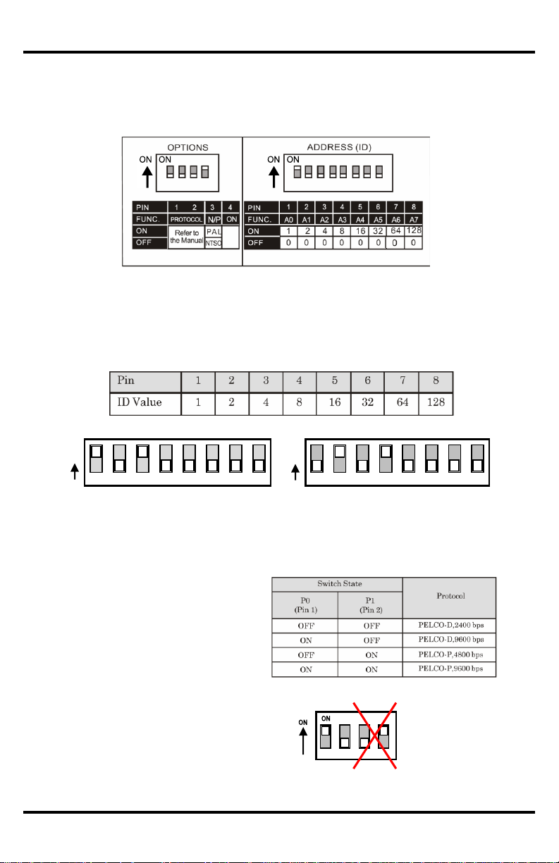
Communication Protocol and Camera ID DIP Switch Setup:
Before the Mini PTZ Camera is installed, first set up the DIP switches to configure the camera ID and the
communications protocol.
Communication Protocol
Camera ID
On
Value
On
Value
1 2 3 4 5 6 7
8
1 2 4 8 16
32
64
128 1 2 3 4
5 6 7 8 1 2 4
8
16
32
64
128 2 + 8 =
10
Example: Camera ID=5
Example: Camera ID=10
4. Set the communication protocol
(4- pin DIP switch):
– Set the proper protocol using Pin 1 and
Pin 2 of the 4-pin DIP switch.
– The protocol for the camera must be
identical to the protocol used by the DVR
or pan/tilt controller. If not, the camera
cannot be controlled by the controller. See
the DVR or pan/tilt controller
manual for protocol information.
– If the protocol of the camera is changed,
the camera must be turned off and then
turned back on for the change to take
effect.
– The factory default protocol is
"Pelco-D, 2400 bps."
– Pins 3 and 4 are set by the factory and
must not be changed. If they are changed,
the camera WILL NOT OPERATE
PROPERLY.
1 + 4
=
5
1. Remove the clear dome of the Mini PTZ Camera by turning it counterclockwise by hand.
2. Look for the two DIP switch blocks near the base of the black plastic dome which surrounds the camera. DO
NOT REMOVE THE BLACK PLASTIC DOME.
3. Set the camera ID (8- pin DIP switch):
– The camera ID is a binary number from 1 to 255. Factory default camera ID is "1."
– Do not use "00000000" as a camera ID.
– The ID number of a particular camera must match the Cam ID setting of the DVR or keyboard controller.
DO NOT TOUCH
PINS 3 AND 4
a
8
Page 9
ENFORCER Mini PTZ Camera
SECO-LARM, U.S.A., INC.
Installation
1. Connect the camera to either the included wall mount or other optional bracket.
2. Run a 24VAC power supply wire, a video cable with a male BNC connector, and a data wire through the
wall to where the camera is to be mounted.
3. Connect the camera's video cable to the video cable coming from the wall. Do not cut the female BNC
connector of the camera's video cable as that will void the warranty.
4. Connect the camera's RS-485 cable to the data wire cable coming from the wall.
Note: If necessary, use the included extension cable for more convenient wiring.
5. Temporarily connect the camera to the power supply. Do not cut the AC power terminal of the
camera's power cable as that will void the warranty.
6. Hold the camera's bracket against the wall or ceiling where it is expected to be mounted, but do not mount
yet. While watching the monitor, operate the camera's pan and tilt functions to ensure that this mounting
location is correct. Use a pencil to mark the location of the screw holes in the mounting bracket.
7. Disconnect the power supply from the camera.
8. Mount the mounting bracket to the wall or ceiling using the included mounting screws. If the wall is made
of drywall, brick, or similar material, it may be necessary to use the included screw anchors.
9. Reconnect the camera's power supply.
10. Program the camera via the on-screen display (OSD) menus from the DVR or keyboard controller.
11. Do a final test of the video camera and monitor.
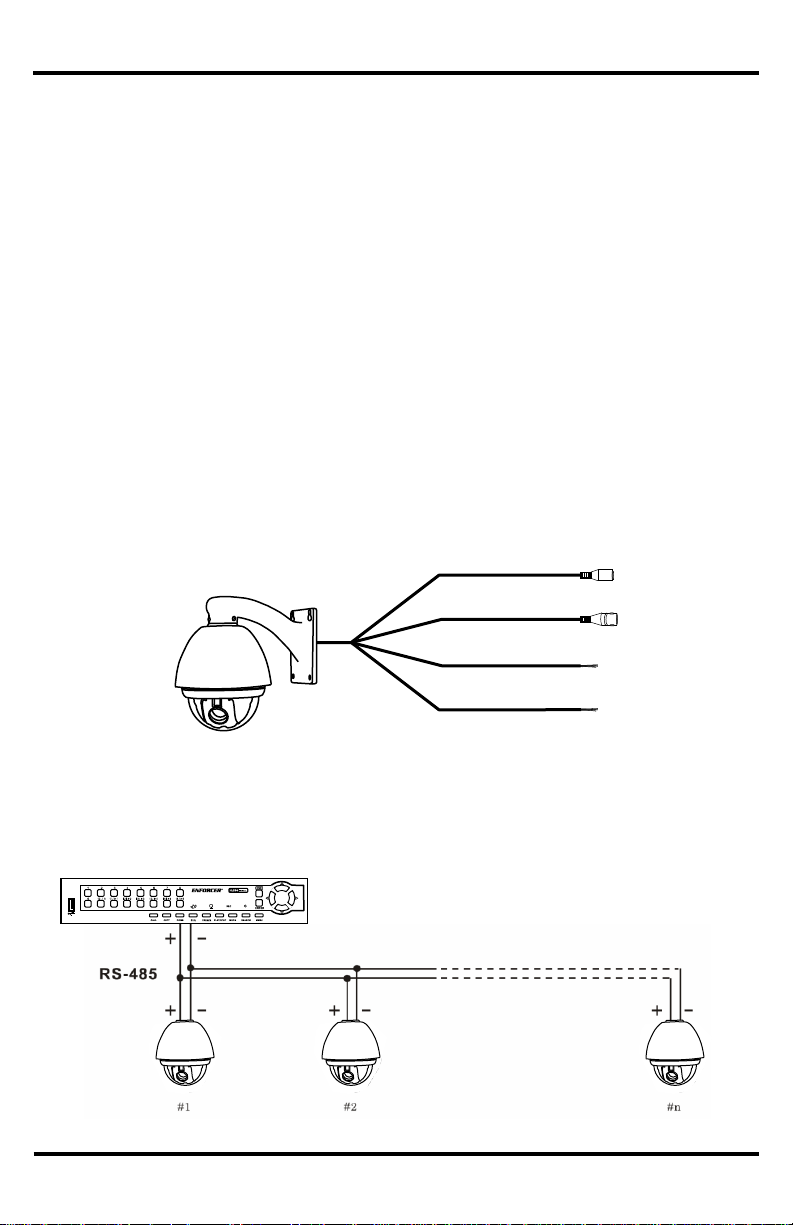
DR-1 Series DVR
Connecting Multiple PTZ Cameras
Basic Installation
24VAC Jack
Video coaxial cable
RS-485 (-) (Yellow)
RS-485 (+) (Orange)
a
9
Page 10

ENFORCER Mini PTZ Camera
SECO-LARM, U.S.A., INC.
Pre-operation Checklist
Before operating this PTZ camera, please note the following:
Double-check that the cables are properly run between the controller and camera, and that all connections are
correct.
Double-check that the camera ID on the controller is the same as the ID of the target camera. The camera ID can
be found by looking at the camera ID DIP switch settings (see page 8).
The Pelco protocol setting of the controller and the camera must be identical. The Pelco protocol setting of the
camera can be found by looking at the communication protocol setup DIP switch settings (see page 8).
Make sure that the camera was rebooted after any of the camera ID or communication protocol setup DIP
switches are changed.
Refer to the controller or DVR manual for information on configuring or operating those devices.
a
10
Page 11

ENFORCER Mini PTZ Camera
SECO-LARM, U.S.A., INC.
Understanding and Operating Preset and Pattern Functions
Standard Pelco-compatible controllers allow the camera operator to do several functions without going through
the full OSD menu, depending on the capabilities of the DVR to which the camera is connected.
The SECO-LARM series of DVRs allows operators to do the following via the "Dome Preset" menu:
Set the camera to remember multiple specific preset locations.
Tell the camera to go to a specific preset location.
Run certain preset functions, including patterns, swings, or grouped functions.
Change certain configuration patterns.
Programming the patterns, swings, or grouped functions, and detailed configuration of the PTZ camera,
requires operators to use the OSD menu. See page 16 for more information.
This PTZ camera can be controlled by any DVR or keyboard controller which uses Pelco-compatible protocols.
When using non-SECO-LARM DVRs, or when using keyboard controllers, the manuals for those devices may
include information on how to operate or program the PTZ camera.
To set or go to a Preset location or use a preset function via a SECO-LARM DVR:
1. Press the "Dome" key. The lower left corner of the screen will change from "REC" to "DOME" to show the
camera is in the Dome Control menu.
2. Press the "1" key to go to the DOME PRESET menu.
3. Use the UP, DOWN, LEFT, and RIGHT buttons to highlight your selection and push ENTER to confirm
your selection.
Note: In most cases, only the GO function will work. Only the preset locations can be programmed via
the DOME PRESET menu. Other functions must be programmed using the OSD menu.
4. Use the UP and DOWN arrows to switch between YES and NO. Go to YES, and press the ENTER key.
See page 13 for a list of preset functions.
11
Page 12

ENFORCER Mini PTZ Camera
SECO-LARM, U.S.A., INC.
Configuring Mini PTZ Camera settings with an ENFORCER DR-1 Series DVR
Step 1
Press Dome on the DVR front panel to access
DVR controls.
Step 2
Press 1 to access the DVR preset menu
Step 3
Use the Up, Down, Left, Right, and Enter
buttons to make a selection.
Step 4
Go to Preset 95 to access Mini PTZ OSD settings.
This will bring up the SPEED DOME CAMERA menu as shown on page 18.
12
Page 13

ENFORCER Mini PTZ Camera
SECO-LARM, U.S.A., INC.
<Go Preset> [95]
:Enters into OSD menu
<Go Preset> [131~134]
:Runs Pattern Function 1~4
<Go Preset> [141~148]
:Runs Swing Function 1~8
<Go Preset> [151~158]
:Runs Group Function 1~8
<Go Preset> [170]
:Sets Camera BLC mode to OFF
<Go Preset> [171]
:Sets Camera BLC mode to ON
<Go Preset> [174]
:Sets Camera Focus mode to AUTO
<Go Preset> [175]
:Sets Camera Focus mode to MANUAL
<Go Preset> [176]
:Sets Camera Focus mode to
SEMI-AUTO
<Go Preset> [177]
:Sets Day and Night mode to AUTO
<Go Preset> [178]
:Sets Day and Night mode to NIGHT
<Go Preset> [179]
:Sets Day and Night mode to DAY
<Go Preset> [190]
:Sets OSD Display mode to AUTO (Except Privacy Mask)
<Go Preset> [191]
:Sets OSD Display mode to OFF (Except Privacy Mask)
<Go Preset> [192]
:Sets OSD Display mode to ON (Except Privacy Mask)
<Go Preset> [193]
:Sets all Privacy Mask Display to OFF
<Go Preset> [194]
:Sets all Privacy Mask Display to ON
Reserved Presets
Configuration Defaults
Default Display Configuration
Default Camera Configuration
Camera ID
ON
Focus Mode
SEMI-AUTO
PTZ Information
AUTO
Digital Zoom
ON
Action Title
AUTO
Line Lock
OFF
Preset Label
AUTO
White Balance
AUTO
Alarm Input
AUTO
Backlight
OFF
North Direction
Pan 0˚
Day & Night
AUTO1
Privacy Zone
Undefined
Brightness
25
Iris
AUTO
Default Motion Configuration
Shutter
ESC
Motion Lock
OFF
AGC
NORMAL
Power Up Action
ON
SSNR
MIDDLE
Auto Flip
ON
SENS-UP
AUTO (4 Frame)
Jog Max Speed
120˚ / sec
Jog Direction
INVERSE
User Edit Data
Freeze In Preset
OFF
Preset 1~94, 96~128
Undefined
Park Action
OFF
Swing 1~8
Undefined
Alarm Action
OFF
Pattern 1~4
Undefined
Group 1~8
Undefined
13
Page 14

ENFORCER Mini PTZ Camera
SECO-LARM, U.S.A., INC.
OSD Main Screen
The OSD main screen shows information about the current situation of the camera while it is operating. This screen is NOT
seen as part of the programming process.
Preset Label
The label of the specific preset.
Action Title
Will be one of the following:
SET PRESET XXX
When PRESET XXX is stored
PRESET XXX
When camera reaches PRESET XXX
PATTERN X
When PATTERN X is in action
SWG X / PRESET XXX
When SWING X is in action
UNDEFINED
When an undefined function is called
Image Flip
Shows that the image is currently flipped vertically by the Auto Flip function
Camera ID
Shows the current camera ID (address)
Alarm Information
This function is reserved for future use
P/T/Z Information
Current Pan/Tilt/Zoom information (4 information points):
Pan angle in degrees
Tilt angle in degrees
Zoom level
Compass direction
Example: (15 / 4 / x 1 / N) means a Pan angle of 15 degrees, a Tilt angle of 4
degrees, Zoom (magnification) level of 1 (100%), and camera facing "North."
OSD Display of Main Screen
Action Title
Alarm
Information
Pan/Tilt/Zoom
Information
Camera ID
Image Flip
Preset
Label
14
Page 15

ENFORCER Mini PTZ Camera
SECO-LARM, U.S.A., INC.
For operating the OSD menus, please note the following:
To access the OSD menu from your DVR, go to Preset 95. For more information on DVR presets and their
functions for the ENFORCER Mini PTZ Camera, please see page 13, Reserved Presets.
Most commands are done on PELCO-compatible DVRs using the front panel keys, including the up, down,
right, and left arrows, or via a panel-mounted joystick. Such operations may also be possible using the
DVR’s remote control.
Note: For ENFORCER DR-1 DVRs, the operations are usually done using the DVR remote control.
For many menu operations, the user must press the SEQ or FREEZE keys. For most DVRs, these are the
keys for focus in (SEQ) and focus out (FREEZE), but may be marked with other words.
For ENFORCER DR-1 Series DVRs, the operations are done using:
o Menu items which have sub-menus are surrounded by “<” and “>” brackets
(For example, <DISPLAY SETUP>).
o To enter a sub-menu, press the SEQ key.
o To go up one level, press the FREEZE key.
o To move from item to item in a menu, use the arrow keys or joystick to move up/down or left/right.
o To change the value of an item, use the arrow keys or joystick to move up/down or right/left.
o To save a value, press the SEQ key.
o To cancel a value or operation, press the FREEZE key.
Operating the OSD Menus
SEQ and FREEZE keys
15
Page 16

ENFORCER Mini PTZ Camera
SECO-LARM, U.S.A., INC.
16
Page 17

ENFORCER Mini PTZ Camera
SECO-LARM, U.S.A., INC.
17
Page 18

ENFORCER Mini PTZ Camera
SECO-LARM, U.S.A., INC.
SPEED DOME CAMERA Menu
<SYSTEM INFORMATION>: Displays system information
and configuration (see menu on page 18).
<DISPLAY SETUP>: Configures the display information
shown on the OSD Main Screen as shown on page 16 (see
menu on page 19).
<DOME CAMERA SETUP>: Configures various functions of
the camera (see menu on page 21).
<SYSTEM INITIALIZE>: Initializes system configuration and
sets all data to factory default configuration (see menu on
page 31).
This menu shows the current configuration information as
configured on page 8. No information can be programmed using
this OSD menu.
SYSTEM INFORMATION Menu
From SPEED DOME CAMERA
FIRMWARE VER
: V2.0
COLOR SYSTEM
: NTSC
PROTOCOL
: PELCO-D
ADDRESS
: 38
BAND RATE
: 9600
SYSTEM INFORMATION
EXIT
BACK
<SYSTEM INFORMATION>
<DISPLAY SETUP>
<DOME CAMERA SETUP>
<SYSTEM INITIALIZE>
SPEED DOME CAMERA
EXIT
18
Page 19

ENFORCER Mini PTZ Camera
SECO-LARM, U.S.A., INC.
DISPLAY SETUP Menu
From SPEED DOME CAMERA
This menu enables or disables the information shown on the
OSD Main Screen (see page 14).
Note that setting an item to "AUTO" means that item will be
displayed only when its value changes.
This menu accesses other OSD menus for configuring a specific
pan direction of the camera as "NORTH" for certain functions,
and for setting privacy zones.
CAMERA ID
: ON
PTZ INFORMATION
: AUTO
ACTION TITLE
: AUTO
PRESET LABEL
: AUTO
ALARM INPUT
: AUTO
<SET NORTH DIRECTION>
<PRIVACY ZONE>
DISPLAY SETUP
EXIT
BACK
This menu sets a specific pan and tilt location as "compass
north," or a certain location on which other functions are
centered.
Using the arrow keys or joystick, point the camera towards the
default location, and then select "NEAR" or "SAVE" to configure
that location as "compass north."
SET NORTH DIRECTION Menu
From DISPLAY SETUP
SET NORTH DIRECTION
MOVE TO TARGET POSITION
[NEAR:SAVE /FAR:CANCEL]
CAMERA ID
[ON/OFF]
PTZ INFORMATION
[ON/OFF/AUTO]
ACTION TITLE
[ON/OFF/AUTO]
PRESET LABEL
[ON/OFF/AUTO]
ALARM INPUT
[AUTO] -- This function is
reserved for future use.
<SET NORTH DIRECTION>
See OSD menu below.
<PRIVACY ZONE>
See OSD menu on page 20.
19
Page 20

ENFORCER Mini PTZ Camera
SECO-LARM, U.S.A., INC.
PRIVACY ZONE Menu
From DISPLAY SETUP
This menu configures an area of the camera’s field of vision so
that it is covered by a gray mask, hiding it. For instance, this
would be used to cover a neighbor’s window, or a sensitive
window of the office.
Once configured, the gray mask automatically appears over that
area every time the camera pans or tilts past it.
MASK NO
1
UNDEFINED
DISPLAY
OFF
CLEAR MASK
CANCEL
<EDIT MASK>
PRIVACY ZONE
EXIT
BACK
EDIT MASK Menu
From PRIVACY ZONE
Move the camera to the target area to be masked and choose
NEAR or SAVE. The mask will be displayed as a gray square.
EDIT MASK 1
MOVE TO TARGET POSITION
[NEAR:SAVE /FAR:CANCEL]
Once the mask is displayed:
• Center the camera on the object to be masked.
• Use the joystick or arrow keys to adjust the mask size.
• Select "NEAR" or "SAVE" to save the mask setting.
EDIT MASK 1
[NEAR:SAVE /FAR:CANCEL]
[ ◄►: ADJUST MASK WIDTH]
[ ▲▼: ADJUST MASK HEIGHT]
MASK NO
1~4. Select the mask number. If that mask
was already configured, the camera will
move to the where it was set. Otherwise,
UNDEFINED will be displayed under
MASK NO.
DISPLAY
[ON/OFF] Shows ON if the selected mask
is active, shows OFF if that mask is not
active.
CLEAR MASK
Deletes data in the selected mask.
<EDIT MASK>
See EDIT MASK menu below.
20
Page 21

ENFORCER Mini PTZ Camera
SECO-LARM, U.S.A., INC.
DOME CAMERA SETUP Menu
From SPEED DOME CAMERA
<CAMERA SETUP>
Goes to the ZOOM CAMERA SETUP menu
for configuring many of the general functions
of the zoom camera module. See page 22.
<MOTION SETUP>
Configures the general functions of the pan
and tilt motions. See page 24
<PRESET SETUP>
Configures up to 127 different preset
locations to which the camera can be
instantly moved. See page 26.
<SWING SETUP>
Configures up to four different swing motions
between two different preset locations. See
page 28.
<PATTERN SETUP>
Configures up to four pan/tilt patterns, with
each pattern consisting of a starting position,
an ending position, and the complete
pan/tilt/halt movement between those two
points. See page 29.
<GROUP SETUP>
Configures up to eight groups of motions,
with each group consisting of any
combination of up to 20 presets, swings,
patterns, and temporary halts in the action.
See page 30.
<CAMERA SETUP>
<MOTION SETUP>
<PRESET SETUP>
<SWING SETUP>
<PATTERN SETUP>
<GROUP SETUP>
DOME CAMERA SETUP
EXIT
BACK
21
Page 22

ENFORCER Mini PTZ Camera
SECO-LARM, U.S.A., INC.
FOCUS MODE
[AUTO / MANUAL / SEMI-AUTO]
Sets the camera focus mode.
"SEMI-AUTO" mode -- In this mode, the camera switches between the
"manual focus mode" and "auto focus mode" depending on the current
operation of the camera. When the camera moves to a PRESET location, the
focus of the camera changes to the focus that was memorized when the
PRESET was configured ("manual focus mode"). During jog operations, the
camera switches to auto focus ("auto focus mode").
DIGITAL ZOOM
[ON / OFF] Sets the digital zooom function ON or OFF. If set to "OFF" the
maximum zoom of the camera is the optical zoom. If set to "ON" the digital
zoom operates when the optical zoom reaches its maximum setting.
LINE LOCK
[ON / OFF] If set to ON, the camera's line lock sync is synchronized with the
AC power. This function might be used if multiple cameras attached to the
same DVR interfere with each other.
IMAGE FLIP
[ON / OFF] When ON, the camera image flips up-side-down.
<WHITE BALANCE SETUP>
In the manual mode, the red and blue color levels can be configured manually.
See below.
<AUTO EXPOSURE
SETUP>
Configures a variety of lighting settings for the camera. See page 23.
ZOOM CAMERA SETUP Menu
From DOME CAMERA SETUP
FOCUS MODE
SEMI-AUTO
DIGITAL ZOOM
ON
LINE LOCK
OFF
IMAGE FLIP
OFF
<WHITE BALANCE SETUP>
<AUTO EXPOSURE SETUP>
ZOOM CAMERA SETUP
EXIT
BACK
WB SETUP Menu (White Balance)
From ZOOM CAMERA SETUP
This menu allows the red and blue color levels to be adjusted automatically
or manually.
WB MODE
[AUTO / MANUAL] In the manual mode, the red and
blue colors can be individually set.
RED ADJUST
[10~60]
BLUE ADJUST
[10~60]
WB MODE
AUTO
RED ADJUST
_ _ _
BLUE ADJUST
_ _ _
WB SETUP - GLOBAL
EXIT
BACK
This menu configures many of the general functions of the zoom camera module.
22
Page 23

ENFORCER Mini PTZ Camera
SECO-LARM, U.S.A., INC.
AE SETUP Menu (Auto Exposure)
From ZOOM CAMERA SETUP
BACKLIGHT
[ON / OFF]
Sets the backlight compensation.
DAY/NIGHT
[AUTO1 / AUTO2DAY / NIGHT]
AUTO1 flips between the day and night
modes faster than AUTO2.
BRIGHTNESS
[0~100]
Adjusts the brightness of the image. The
IRIS, SHUTTER, and gain settings are all
adjusted automatically as the
BRIGHTNESS is adjusted.
IRIS
[AUTO / MANUAL (0~100)]
If IRIS is set to AUTO, the IRIS of the
camera is set automatically according to
the SHUTTER, which should be manually
set.
If IRIS is set to MANUAL, the IRIS setting
should be manually set while the
SHUTTER is set to ESC or A.FLICKER.
SHUTTER
[ESC / A.FLICKER / MANUAL]
(x1/60~1/120,000 sec.)
If IRIS is set to MANUAL and SHUTTER
is set to ESC (electronic shutter control),
the SHUTTER is automatically set
according to the IRIS setting.
Set SHUTTER to A.FLICKER (flickerless)
to automatically compensate for CFL light
flicker. If interference from CFL light flicker
persists, set the SHUTTER to 1/100second for NTSC or 1/120-second for PAL
systems.
If SHUTTER is to be set manually, set
IRIS to MANUAL.
AGC
[OFF / NORMAL / HIGH]
AGC (auto gain control) enhances the
camera image brightness automatically if
the light level of the image is too low.
SSNR
[OFF / LOW / MIDDLE / HIGH]
SSNR noise reduction enhances images
by reducing signal noise when the gain
level of the image is too high.
SENS-UP
[AUTO (2~128) / OFF]
When set for AUTO, the SHUTTER is
automatically adjusted so that multiple
frames are combined into a single frame
in low-light conditions. For instance, when
set to "8" the images from eight frames
are combined into one frame to increase
the light level. However, this also creates
"ghost" images.
BACKLIGHT
OFF
DAY/NIGHT
AUTO
BRIGHTNESS
25
IRIS
AUTO
SHUTTER
ESC
AGC
NORMAL
SSNR
MIDDLE
SENS-UP
AUTO
AE SETUP - GLOBAL
EXIT
BACK
23
Page 24

ENFORCER Mini PTZ Camera
SECO-LARM, U.S.A., INC.
MOTION SETUP Menu
From DOME CAMERA SETUP
MOTION LOCK
[ON / OFF]
If ON, the user is prevented from configuring or deleting
PRESET, SWING, PATTERN, or GROUP settings.
However, those settings can still be used during
operations. If OFF, the user is allowed to configure or
delete those settings using the OSD menu.
PWR UP ACTION
[ON / OFF]
When ON, if power is unexpectedly cut to the camera
and restored, the camera continues to operate the last
action that was being performed before power was cut.
This includes most PRESET, SWING, PATTERN, or
GROUP actions.
AUTO FLIP
[ON / OFF]
If ON, the image is automatically vertically flipped when
the camera tilts below its center.
JOG MAX SPEED
(1°/sec.~360°/sec.)
This sets the maximum jog speed, which is the pan and
tilt speed of the camera when operated by the user. The
jog speed is also automatically adjusted according to the
camera's zoom. As the zoom level increases, the pan
and tilt jog speed decrease.
JOG DIRECTION
[INVERSE / NORMAL]
This determines whether the controls will be inverse or
normal when operating the pan and tilt of the camera.
FRZ IN PRESET
[ON / OFF]
If the Freeze in Preset function is turned ON, the onscreen camera image at the beginning of a PRESET
action is frozen while the camera moves from the
starting position to the ending position, as programmed
by the user. If turned OFF, the on-screen camera image
moves as the camera moves from the starting to ending
position
<PARKING ACTION SETUP>
Determines what the camera will do if it receives no PTZ
command during a preset time. See page 25.
<ALARM INPUT SETUP>
This is a reserved function, and is currently not available
MOTION LOCK
OFF
PWR UP ACTION
ON
AUTO FLIP
ON
JOG MAX SPEED
120/SEC
JOG DIRECTION
INVERSE
FRZ IN PRESET
OFF
<PARKING ACTION SETUP>
<ALARM INPUT SETUP>
MOTION SETUP
EXIT
BACK
Configures the general functions of the pan and tilt motions.
24
Page 25

ENFORCER Mini PTZ Camera
SECO-LARM, U.S.A., INC.
PARKING ACTION SETUP Menu
From MOTION SETUP
PARK ENABLE
[ON / OFF]
If set to ON, the camera runs an assigned
function automatically if there is no PTZ
command during the configured "WAIT TIME.”
WAIT TIME
[1 minute to 4 hours]
The time the PTZ camera waits before running
the assigned function can be set by the number of
minutes. This time is displayed in the "hh:mm:ss"
format
PARK ACTION
[HOME / PRESET / PATTERN / SWING /
GROUP]
• HOME — Camera moves to the
"HOME" position
• PRESET — Camera moves to the specified
"PRESET" position
• PATTERN — Camera performs the specified
"PATTERN" action
• GROUP — Camera performs the specified
"GROUP" action
Note: The PRESET, PATTERN, or GROUP
option requires the input of which position
or action is to be done.
PARK ENABLE
OFF
WAIT TIME
00:10:00
PARK ACTION
HOME
PARKING ACTION SETUP
EXIT
BACK
This menu sets what the camera will do if it receives no PTZ
command during a preset time.
25
Page 26

ENFORCER Mini PTZ Camera
SECO-LARM, U.S.A., INC.
PRESET MENU
From DOME CAMERA SETUP
PRESET NO.
[1~94, 96~128]
If the PRESET number has already been
defined, the camera immediately moves
to the pre-set PRESET position and
characteristics. If not, "UNDEFINED" is
shown on the screen
Note: If a PRESET position is already
defined, the user can make
changes by selecting that
PRESET position number and
then changing the SCENE,
LABEL, and CAM ADJUST
settings.
CLR PRESET
[CANCEL / ON]
Choose "CANCEL" to delete the current
PRESET data.
<EDIT SCENE>
Redefines the current PRESET scene
position. See page 27
<EDIT LABEL>
Allows user to display a note about this
preset position when the camera moves
to the PRESET position, up to a
maximum of 10 characters.
CAM ADJUST
[GLOBAL / LOCAL]
This sets the WB (white balance) and AE
(auto exposure) modes. "GLOBAL" mode
means that the WB and AE settings for
all PRESET positions are the same as
configured in the WB SETUP menu
under the ZOOM CAMERA SETUP menu
(see page 22). "LOCAL" mode means
that each PRESET position has its own
WB and AE settings
NOTE: The <EDIT LABEL> and CAM ADJUST screens are
not visible unless the <EDIT SCENE> function
is selected.
PRESET NO.
1
CLR PRESET
CANCEL
<EDIT SCENE>
<EDIT LABEL>
CAM ADJUST
GLOBAL
PRESET MENU
EXIT
BACK
This menu configures up to 127 different preset locations to
which the camera can be instantly moved.
26
Page 27

ENFORCER Mini PTZ Camera
SECO-LARM, U.S.A., INC.
EDIT SCENE Menu
From PRESET MENU
This menu redefines the current PRESET scene position.
1. Use the joystick or arrow keys to move the camera to the
desired position.
2. Press the "NEAR" key to save the new camera position, or
press the "FAR" key to cancel this position.
EDIT SCENE – PRESET 1
[NEAR : SAVE
MOVE TO TARGET POSITION
/FAR: CANCEL]
EDIT LABEL Menu
From PRESET MENU
[ █ ]
------------------------------
1 2 3 4 5 6 7 8 9 0
OK
A B C D E F G H I J K
L M N O P Q R S T U
V W X Y Z a b c d e g
h i j k l m n o q r s t u
v w x y v < > - / : . ←
CANCEL
CAM ADJUST
GLOBAL
EDIT LABEL – PRESET 1
3. Press the "NEAR" key to save the new label, or press the
"FAR" key to cancel this label.
-----------------------------
1 2 3 4 5 6 7 8 9 0
OK
A B C D E F G H I J K
L M N O P Q R S T U
V W X Y Z a b c d e g
h i j k l m n o q r s t u
v w x y v < > - / : . ←
CANCEL
Space
Back Space
Character to
be chosen
This menu allows the user to display a note about this PRESET
position every time the camera moves to the position, up to a
maximum of 10 characters.
1. The reverse-color rectangle serves as the cursor for the
message, while a rectangle box shows the character to be
chosen.
EDIT LABEL – PRESET 1
[ █ ]
Current Cursor Location
2. Using the joystick or the arrows, move the rectangular box
to highlight the appropriate character. Press the "NEAR"
key to add that character to the message.
Note: To delete a character, choose the back arrow.
27
Page 28

ENFORCER Mini PTZ Camera
SECO-LARM, U.S.A., INC.
SWING SETUP Menu
From DOME CAMERA SETUP
SWING NO.
[1 ~ 8]
Selects which SWING motion to edit. Choose 1
through 8. If a selected SWING motion has not
been defined, "NOT USED" is displayed in the first
and second positions for that motion
1ST POS.
[PRESET 1 ~ 94 or 96 ~ 128]
2ND POS.
[PRESET 1 ~ 94 or 96 ~ 128]
Select the two PRESET positions between which
the SWING motion will operate. NOTE -- If a
selected PRESET was not previously defined via
the OSD programming, "UNDEFINED"
will be displayed.
SWING SPEED
Programs the speed at which the camera moves,
between the two PRESET positions.
CLEAR SWING
[CANCEL / OK]
Choose “OK” to delete the data in the selected
SWING.
SWING NO.
1
1ST POS.
NOT USED
2ND POS.
NOT USED
SWING SPEED
30/SEC
CLEAR SWING
CANCEL
SWING SETUP
EXIT
BACK
This menu configures up to eight different swing motions back and forth
between two different PRESET positions.
When the SWING function operates, the camera moves (pans and tilts) to
the PRESET position that was set as the "1ST POS." and then moves
clockwise to the PRESET position set as "2ND POS." At that point, the
camera moves counterclockwise back to the "1ST POS." It then repeats
that motion back and forth between the two PRESET positions until another
command is inputted.
EDIT LABEL – PRESET 1
SWING NO.
1
1ST POS.
PRESET 5
2ND POS.
NOT USED
UNDEFINED
28
Page 29

ENFORCER Mini PTZ Camera
SECO-LARM, U.S.A., INC.
PATTERN SETUP Menu
From DOME CAMERA SETUP
PATTERN NO.
1
UNDEFINED
CLR PATTERN
CANCEL
<EDIT PATTERN>
PATTERN SETUP
EXIT
BACK
Configures up to four pan/tilt patterns, with each pattern consisting of a
starting position, an ending position, and the complete pan/tilt/halt movement
between those two points .
PATTERN NO
[1 ~ 4]
Selects which PATTERN number to edit. If the
selected PATTERN number has not yet been
programmed, "UNDEFINED" will be displayed
under the selected PATTERN number.
CLR PATTERN
[CANCEL / OK]
Choose "OK" to delete the data in the selected
PATTERN
<EDIT PATTERN>
Goes to the "EDIT PATTERN" menu. See below.
EDIT PATTERN Menu
From PATTERN SETUP
1. Use the joystick or arrow keys to move the camera view to the
appropriate starting position for the pattern, and set the
desired zoom.
To start the pattern recording, press the NEAR key. To exit this
menu without saving the pattern, press the FAR key.
EDIT PATTERN 1
[NEAR:START /FAR:CANCEL]
MOVE TO START POSITION
2. Use the joystick or arrow keys to move the camera along the
desired path until the end. As the camera is moving, the path
is being saved into its memory.
Note: While setting the PATTERN, any time the camera
pauses will also be saved as part of the pattern.
The total memory size and available memory is displayed on
the screen as a bar.
3. To save this pattern, press the NEAR key. To cancel the
recording of the PRESET pattern, press the FAR key.
EDIT PATTERN 1
0 / 0 / x 1 / N
[NEAR:SAVE /FAR:DELETE]
29
Page 30

ENFORCER Mini PTZ Camera
SECO-LARM, U.S.A., INC.
GROUP SETUP Menu
From DOME CAMERA SETUP
GROUP NO.
1
UNDEFINED
CLEAR GROUP
CANCEL
<EDIT GROUP>
GROUP SETUP
EXIT
BACK
Configures up to eight groups of motions, with each group
consisting of any combination of up to 20 actions, including
PRESETS, SWINGS, PATTERNS, and temporary halts in
the action.
GROUP NO
[1 ~ 4]
Selects which GROUP number to edit. If
the selected GROUP number has not yet
been programmed, "UNDEFINED" will be
displayed under the selected GROUP
number
CLR GROUP
[CANCEL / OK]
Choose "OK" to delete the data in the
selected GROUP
<EDIT GROUP>
Goes to the "EDIT GROUP" menu. See
below
NO ACTION ### DWELL OPT
1
NONE
2
NONE
3
NONE
4
NONE
5
NONE
EDIT GROUP 1
CANCEL [NEAR:EDIT]
SAVE
NO ACTION ### DWELL OPT
1
NONE
2
NONE
3
NONE
4
NONE
5
NONE
EDIT GROUP 1
CANCEL
[▲▼:CHANGE VAL.]
SAVE [◄►:MOVE CURSOR]
NO ACTION ### DWELL OPT
1
NONE
2
NONE
3
NONE
4
NONE
5
NONE
EDIT GROUP 1
CANCEL [FAR : EDIT :END]
SAVE [NEAR:EDIT ACT]
1. Press the NEAR key on the "NO" line to start the
GROUP setup.
2. Use the joystick or arrow keys to move up and down to
select the number of the ACTION to configure. There are
a maximum of 20 ACTIONS which can be done in
each GROUP.
3. Set the ACTION, DWELL time, and OPT (option) for each
action. The item ready for configuring is displayed in
reverse text. Move the joystick/arrow cursor right and left to
select items to configure, and then move the joystick/arrow
cursor up and down to change the value of the ACTION.
ACTION ###
[NONE / PRESET / SWING / PATTERN]
DWELL
[0 seconds ~ 4 minutes]
NOTE — DWELL configures how long the
camera waits between each ACTION.
OPT
Option. If PRESET is selected as the
ACTION, this will be the PRESET speed.
If PATTERN or SWING is selected as the
ACTION, set OPT for the number of times
the PATTERN or SWING is repeated.
30
Page 31

ENFORCER Mini PTZ Camera
SECO-LARM, U.S.A., INC.
NO ACTION ### DWELL OPT
1
PRESET
1 00 : 03 : 360
2
NONE
3
NONE
4
NONE
5
NONE
EDIT GROUP 1
CANCEL [FAR : EDIT :END]
SAVE [NEAR:EDIT ACT]
4. Configure each ACTION, ###, DWELL, and OPT.
In the sample screen on the left, ACTION #1 is the
command for the PTZ camera to go to PRESET #1 using
the PRESET speed of 360 as programmed in the PRESET
SETUP menu (see page 26), and stay at that position for 3
seconds before moving to the next action.
5. After setting up an ACTION, use the NEAR key to move the
cursor to the NO column, and then move the cursor up and
down to select another ACTION to configure or modify.
6. After setting up all the ACTIONs for this GROUP, press the
FAR key to exit. At this point, the cursor will move to SAVE.
Press the NEAR key to save the data.
NO ACTION ### DWELL OPT
1
PRESET
1 00 : 03 : 360
2
NONE
3
NONE
4
NONE
5
NONE
EDIT GROUP 1
CANCEL
[▲▼:CHANGE VAL.]
SAVE [◄►:MOVE CURSOR]
NO ACTION ### DWELL OPT
1
PRESET
1 00 : 03 : 360
2
NONE
3
NONE
4
NONE
5
NONE
EDIT GROUP 1
CANCEL
SAVE
SYSTEM INITIALIZE Menu
From SPEED DOME CAMERA
CLEAR ALL DATA
NO
•CLR DISPLAY SET
NO
•CLR CAMERA SET
NO
•CLR MOTION SET
NO
•CLR EDIT DATA
NO
REBOOT CAMERA
NO
REBOOT SYSTEM
NO
SYSTEM INITIALIZE
EXIT
SAVE
This menu lets the user clear selected programmed data, clear all
programmed data, or reboot the entire camera or system.
CLEAR ALL DATA
Deletes all user-programmed data including
DISPLAY SETUP, CAMERA SETUP, and
MOTION SETUP.
CLR DISPLAY SET
Clears the DISPLAY SETUP data and initializes
the configuration of that data.
CLR CAMERA SET
Clears the CAMERA SETUP data and initializes
the configuration of that data.
CLR MOTION SET
Clears the MOTION SETUP data and initializes
the configuration of that data.
CLR EDIT DATA
Deletes all PRESET SETUP data, SWING SETUP
data, PATTERN SETUP data, and GROUP
SETUP data.
REBOOT CAMERA
Reboots the zoom camera module.
REBOOT SYSTEM
Reboots the entire PTZ camera.
31
Page 32

ENFORCER Mini PTZ Camera
SECO-LARM, U.S.A., INC.
MiEV-7105-NPEQ_1111.docx
PISCN4
IMPORTANT
Users and installers of this product are responsible for ensuring that use of this product complies with all national, state, and
local laws and statutes related to monitoring and recording audio and video signals. SECO-LARM will not be held
responsible for the use of this product in violation of any current laws or statutes.
WARNING
Stop using the camera if you see a malfunction such as smoke or unusual heat, as it could cause fire or electric shock. Do
not open the case of this device, as there are no user-serviceable components inside.
FCC COMPLIANCE STATEMENT
Information to the user: This equipment has been tested and found to comply with the limits for a class B digital device,
pursuant to part 15 of the FCC rules. These limits are designed to provide reasonable protection against harmful interference
when the equipment is operated in a commercial environment. This equipment generates, uses, and can radiate radio
frequency energy and, if not installed and used in accordance with the instruction manual, may cause harmful interference to
radio communications. Operation of this equipment in a residential area is likely to cause harmful interference in which case
the user will be required to correct the interference at his or her own expense.
WARRANTY: This SECO-LARM product is warranted against defects in material and workmanship while used in normal
service for a period of one (1) year from the date of sale to the original consumer customer. SECO-LARM’s obligation is
limited to the repair or replacement of any defective part if the unit is returned, transportation prepaid, to SECO-LARM.
This Warranty is void if damage is caused by or attributed to acts of God, physical or electrical misuse or abuse, neglect,
repair or alteration, improper or abnormal usage, or faulty installation, or if for any other reason SECO-LARM determines that
such equipment is not operating properly as a result of causes other than defects in material and workmanship.
The sole obligation of SECO-LARM, and the purchaser’s exclusive remedy, shall be limited to replacement or repair only, at
SECO-LARM’s option. In no event shall SECO-LARM be liable for any special, collateral, incidental, or consequential
personal or property damages of any kind to the purchaser or anyone else.
NOTICE
The information and specifications printed in this manual are current at the time of publication. However, the SECO-LARM
policy is one of continual development and improvement. For this reason, SECO-LARM reserves the right to change
specifications without notice. SECO-LARM is also not responsible for misprints or typographical errors.
Copyright © 2011 SECO-LARM U.S.A., Inc. All rights reserved. This material may not be reproduced or copied, in whole or
in part, without the written permission of SECO-LARM.
SECO-LARM U.S.A., Inc.
16842 Millikan Avenue, Irvine, CA 92606
Tel: 800-662-0800 / 949-261-2999
Website: www.seco-larm.com
E-mail: sales@seco-larm.com
Also Available from SECO-LARM:
EV-7100CEILM
EV-7100POLEM
EV-7100CORNM
EV-7100FLUSM
Ceiling
Bracket
Pole-Mounting
Bracket
Corner-Mounting
Bracket
Flush-Mount
Bracket
RD-304-D1Q
EVA-RS1
EVT-PB1Q
EVT-PB1-31RQ
Data
Distributor
RS-232 to RS-485
Converter
Passive
Video Balun
Passive
Video/Power/Data Balun
DR-116-1.0TQ
DR-1 Series
Digital Video Recorder
EVP-1SA8P16UL
AC Power
Supply
32
 Loading...