

SECO-LARM Enforcer EV-1626-NKGQ, Enforcer EV-1626-PKGQ, Enforcer EV-1626-NWGQ, Enforcer EV-1626-PWGQ Installation Manual
Page 1
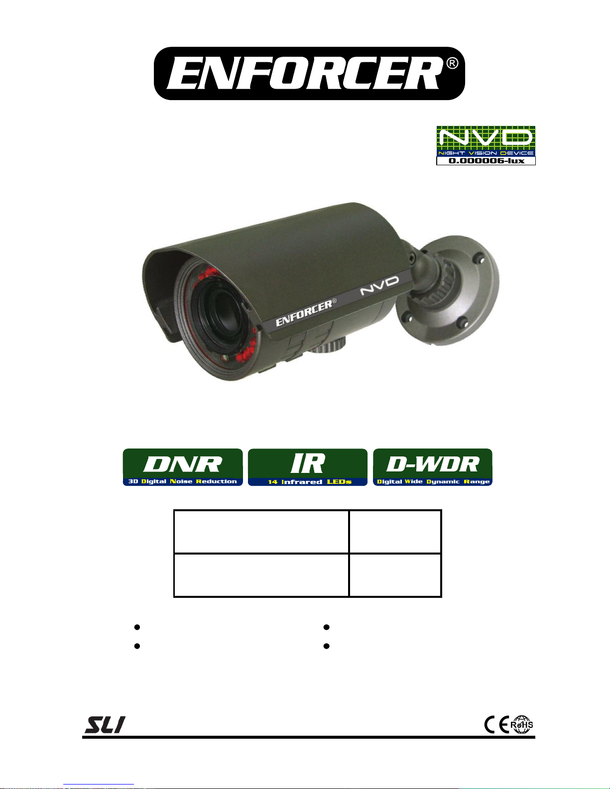
NVD Bullet Cameras
Installation Manual
Note: Products with model numbers that end with “Q” or that have a round green “Q” sticker are RoHS compliant.
EV-1626-NKGQ (NTSC)
EV-1626-PKGQ (PAL)
2.8~12mm
EV-1626-NWGQ (NTSC)
EV-1626-PWGQ (PAL)
6~50mm
3 Cameras in 1:
1
/3” Sony Super HAD CCD
12VDC/24VAC
OSD with service monitor port
600 TV lines
NVD Bullet Cameras have an ultra-low lux rating of 0.000006 allowing the
camera to see in almost total darkness.
Page 2
NVD Bullet Cameras
2 SECO-LARM U.S.A., Inc.
1 x DC plug with
terminal block
1 x Service monitor
port connector
EV-1626-NKGQ (NTSC)
EV-1626-PKGQ (PAL
EV-1626-NWGQ (NTSC)
EV-1626-PWGQ (PAL)
Type
IR LED Bullet Camera
CCD
1
/3” SONY Super HAD CCD
Resolution
600 TV lines
Pickup Elements
NTSC: 768x494 pixels
PAL: 752x582 pixels
Video Output / Service Monitor Port
Composite video 1.0Vp-p into 75Ω + test connection
Video Output Format
NTSC
Lens (DC Auto Iris)
2.8~12mm
6~50mm
Minimum Illumination
0.000006-lux (LEDs on) 0.05-lux (LEDs off)
S/N Ratio
>52dB (weight on)
On Screen Display (OSD)
Built-in and controlled by internal joystick
Motion Detection
4 zones
Backlight Compensation
HLC/BLC/Off
White Balance
ATW / AWC / MANUAL (1800°~10,500° K)
Electronic Shutter
Auto/Manual (adjustable range: 1/60~1/120,000 sec)
Auto Gain
Selectable: Low, Middle, High, Off
3-DNR (DNR with 3D filtering)
On/Off (adjustable range: 0~100)
Day & Night (Color)
Selectable: Color, Auto, B/W
Sharpness
On/Off (adjustable range: 0~31)
Privacy
On/Off (8 programmable zones)
IP Rating
IP66
# of Infrared LEDs
14 (850nm)
Power Source
12VDC/24VAC Dual Voltage
Current Draw
12VDC: 200mA(LEDs off), 310mA (LEDs on)
24VAC: 2W (LEDs off), 3W (LEDs on)
Operating Temperature
14°~122° F (-10°~50° C)
Dimensions (LxWxH)
7” x23/4” x31/2” (180x70x90 mm) (with sunshield)
Weight
18-oz (500g)
Specifications:
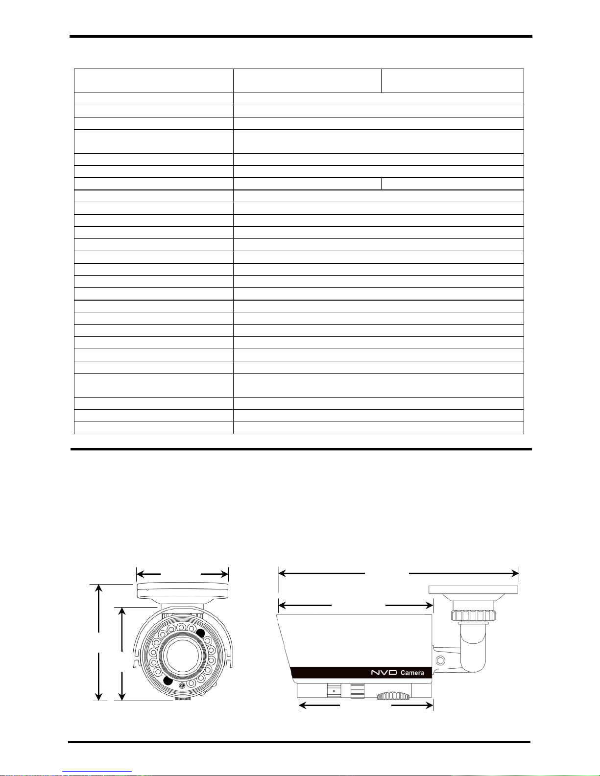
Dimensions:
423/32” (120mm)
7” (180mm)
315/16” (100mm)
23/4” (70mm)
31/2”
(90mm)
219/32”
(66mm)
Parts List:
1 x Camera with bracket
1 x Mounting plate
1 x Sunshield
4 x Mounting screws
4 x Hex screws
1 x Hex wrench
ENFORCER
®
Page 3

NVD Bullet Cameras
SECO-LARM U.S.A., Inc. 3 3 SECO-LARM U.S.A., Inc. 33 3
1. Please read this manual carefully and keep it for
future reference.
2. Use the camera within given temperature and
electrical limits.
3. Do not aim the LEDs directly at the eyes when the
LEDs are on.
4. Do not point the camera at the sun. Heat could
damage the camera, even when not in use.
5. Do not mount the camera in areas exposed to
radiation, strong magnetic fields, or strong
electrical signals.1
6. Do not open or disassemble the camera. There are
no field-serviceable parts inside.
7. Do not drop the camera or subject it to
strong vibrations.
1
Note: Many video monitors produce strong
electromagnetic fields close to the display CRT,
especially when the monitor is turned on or
during de-Gaussing, which occurs automatically
with many monitors when turning on.
1. Run a 12VDC or 24VAC power supply wire and a
video cable with a male BNC connector through the
wall to where the camera is to be mounted.2
2. Temporarily connect the camera to the power
supply. Do not cut DC jack or female BNC
connector as warranty will be voided. If needed,
use the included SECO-LARM DC plug with
terminal block.
3. Remove service cover and connect included service
monitor port connector to service monitor port.
4. Connect the service monitor port connector’s BNC to
a test monitor.
5. While watching the monitor, hold the camera against
the wall or ceiling by hand where it is to be mounted,
then turn the camera until it is certain that this
mounting location is correct. Use a pencil to mark
the location of the four screw holes in the mounting
plate.
6. Mount the mounting plate to the wall or ceiling using
the four included mounting screws. If the
wall is made of drywall, brick, or similar material,
it may be necessary to use screw anchors
(not included).
7. Mount the camera base to the mounting plate using
the four included hex screws.
8. Adjust the camera angle.
9. Adjust zoom and focus. Then use the OSD control
joystick to adjust camera settings. (See OSD
manual).
10. Disconnect the power supply and service
monitor connector.
11. Put the sunshield on the camera.
12. Do a final test of the video camera and monitor.
2
Note: The base also allows for surface running of the
wires. However, for a cleaner, more secure
installation, run the wires through the wall.
Installation:
Before Starting:
Overview:
A. Camera
B. Adjustable sunshield
C. Mounting plate
D. Camera base
E. Hex screws
F. Mounting screws
G. Focus
H. Zoom
I. Service cover
J. Female BNC
connector
(video out)
K. DC jack
L. DC plug with
terminal block
M. Service monitor port,
OSD joystick
A
B
C
D E F
H
G
I, M
OSD joystick
Connect service
monitor port connector
to service monitor port
Important:
Do not cut DC jack (K) or
female BNC connector (J) as
warranty will be voided.
K J L
Page 4

NVD Bullet Cameras
4 SECO-LARM U.S.A., Inc.
IMPORTANT
Users and installers of this product are responsible for ensuring this product complies with all national, state, and local laws and
statutes related to monitoring and recording audio and video signals. SECO-LARM will not be held responsible for the use of this
product in violation of any current laws or statutes.
WARNING
Stop using the camera if you see a malfunction such as smoke or unusual heat, as it could cause fire or electric shock. Do not
open the case of this device, as there are no field-serviceable components inside.
FCC COMPLIANCE STATEMENT
Information to the user: This equipment has been tested and found to comply with the limits for a class B digital device, pursuant
to part 15 of the FCC rules. These limits are designed to provide reasonable protection against harmful interference when the
equipment is operated in a commercial environment. This equipment generates, uses, and can radiate radio frequency energy
and, if not installed and used in accordance with the instruction manual, may cause harmful interference to radio communications.
Operation of this equipment in a residential area is likely to cause harmful interference in which case the user will be required to
correct the interference at his own expense.
WARRANTY: This SECO-LARM product is warranted against defects in material and workmanship while used in normal service
for a period of three (3) year from the date of sale to the original consumer customer. SECO-LARM’s obligation is limited to the
repair or replacement of any defective part if the unit is returned, transportation prepaid, to SECO-LARM.
This Warranty is void if damage is caused by or attributed to acts of God, physical or electrical misuse or abuse, neglect, repair, or
alteration, improper or abnormal usage, or faulty installation, or if for any other reason SECO-LARM determines that such
equipment is not operating properly as a result of causes other than defects in material and workmanship.
The sole obligation of SECO-LARM, and the purchaser’s exclusive remedy, shall be limited to replacement or repair only, at
SECO-LARM’s option. In no event shall SECO-LARM be liable for any special, collateral, incidental, or consequential personal or
property damages of any kind to the purchaser or anyone else.
NOTICE
The information and specifications printed in this manual are current at the time of publication. However, the SECO-LARM policy
is one of continual development and improvement. For this reason, SECO-LARM reserves the right to change specifications
without notice. SECO-LARM is also not responsible for misprints or typographical errors.
Copyright © 2010 SECO-LARM U.S.A., Inc. All rights reserved. This material may not be reproduced or copied, in whole or in
part, without the written permission of SECO-LARM.
U.S.A., Inc.
16842 Millikan Avenue, Irvine, CA 92606 Website: www.seco-larm.com
Tel: 800-662-0800 / 949-261-2999 Fax: 949-261-7326 E-mail: sales@seco-larm.com
MiEV-1626NxGQ_1105.docx
PIKHR1
Made in Korea
Troubleshooting
The screen is blank.
Check that the camera is powered up.
Check that the power supply’s polarity is correct.
Check that the monitor is powered up.
Check that the video cable connecting the camera to the
monitor is connected properly.
The screen image is dim.
Clean the lens using a soft, clean cloth.
Check that the light source is adequate.
The screen image has poor contrast.
Adjust the monitor’s contrast knob.
Change the position of the camera.
The screen image flickers.
Change the position of the camera.
The screen image is distorted.
Change the position of the camera.
The camera case is hot.
Check that the correct power supply is in use.
IR LEDs do not turn on.
Check that the correct power supply is in use.
 Loading...