

Page 1
Installation Manual
®
ENFORCER
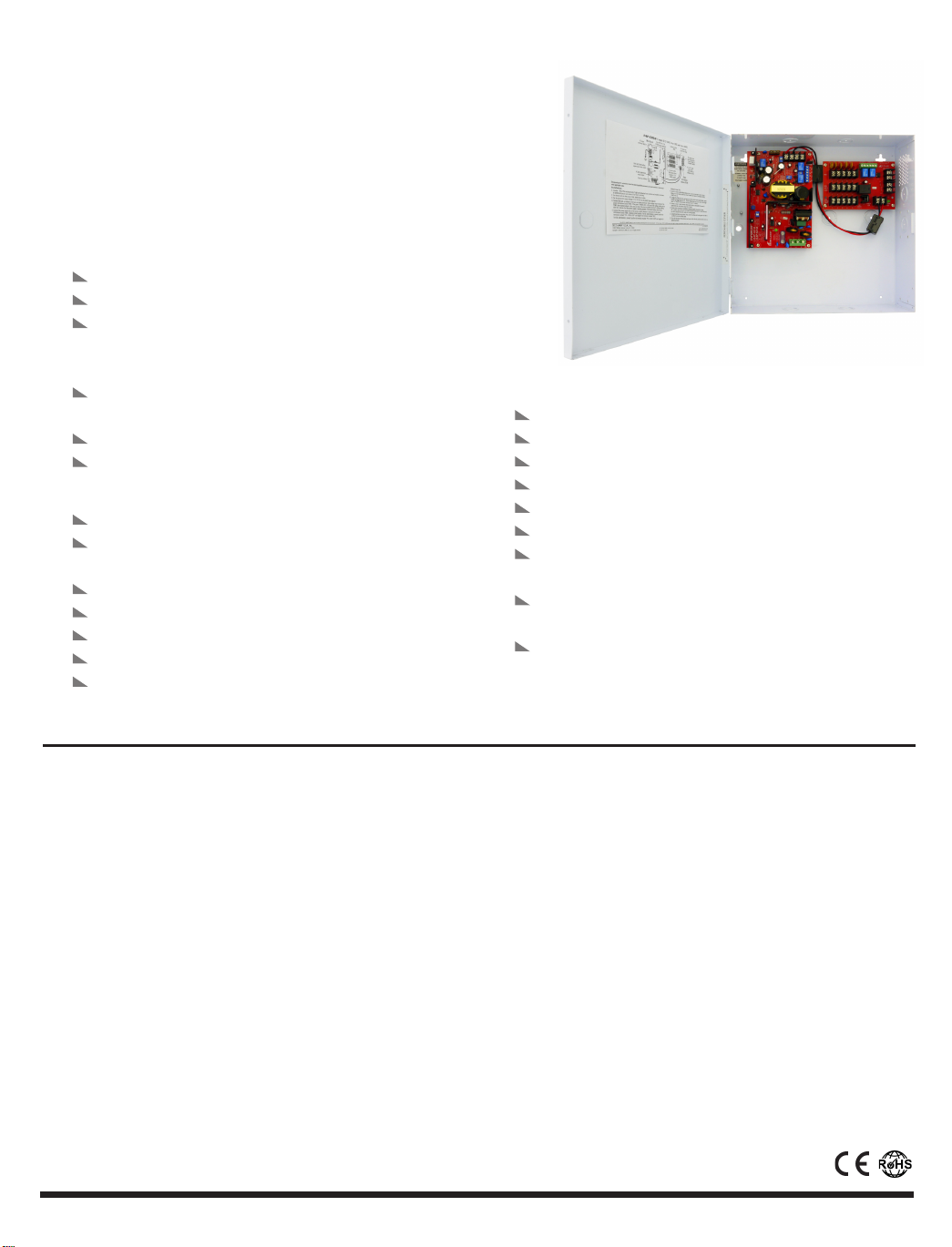
EAP-5D5Q (5A@12VDC, 2.5A@24VDC)
Access Control Power Supply
SPECIFICATIONS:
POWER:
Input: 110~240VAC.
Output: Field selectable 12VDC or 24VDC output.
Five individually fused (PTC*-type fuses) power
outputs. Each output operates both in fail-safe and
fail-secure modes.
Each individually fused (PTC*-type fuses) output
rated at 1.1 Amp.
AC input fuse rated at 3.15 Amps (glass fuse).
Filtered and electronically regulated outputs.
ENCLOSURE:
Heavy-duty steel case to protect the power connections.
Removable steel cover for easy access to power
connections.
Ventilation holes to prevent heat build-up.
Room for two 7AH batteries (not included).
6-foot power cord and battery leads included.
Dimensions - 121/8"x121/4"x
Knock-out on the cover for optional cam lock.
* Positive Temperature Coefficient
39/16"(308x311x90 mm).
FEATURES:
AC power failure supervision relay.
Battery fail / low battery supervision relay.
DC output fail supervision relay.
Auxiliary output relay.
Adjustable voltage range to compensate for voltage drop.
Built-in back-up battery charger (batteries not included).
DIP switch selectable 2.2kΩ End-of-Line (EOL) resistor for
AC failure and battery failure supervision relays.
DIP switch selectable delay timer (5 sec., 5 min., 5 hours)
for AC failure supervision relay.
LED status indicator for AC input, DC outputs, and
channel outputs.
What it is:
The ENFORCER Access Control Power Supply centralizes the power
sources for multiple 12 or 24 VDC-powered electronic locks or
accessories used in access control system. The power input and all fused
power outputs are enclosed in one heavy-duty, easy-to-install enclosure.
As a result, an ENFORCER Access Control Power Supply can replace
multiple separate individual power sources.
Note before installation:
The ENFORCER Power Supply is not waterproof or weatherproof.
Therefore, it must be mounted indoors where it cannot be exposed to
rain or other moisture.
Installation must be done by qualified personnel, and should
conform to local and all other applicable codes.
Installation:
1. Find a good location for the enclosure. The enclosure should be
mounted where it is out of sight and protected from moisture and
the weather, but where an authorized person can have access for
servicing in the future.
Note: Products with model numbers that end with "Q" or that have a round green “Q” sticker are RoHS compliant.
NOTE: Make sure the space where the enclosure is to be
mounted has adequate ventilation. Otherwise, heat buildup inside
the enclosure could damage the electronic parts or cause the PTC
fuses to trip needlessly.
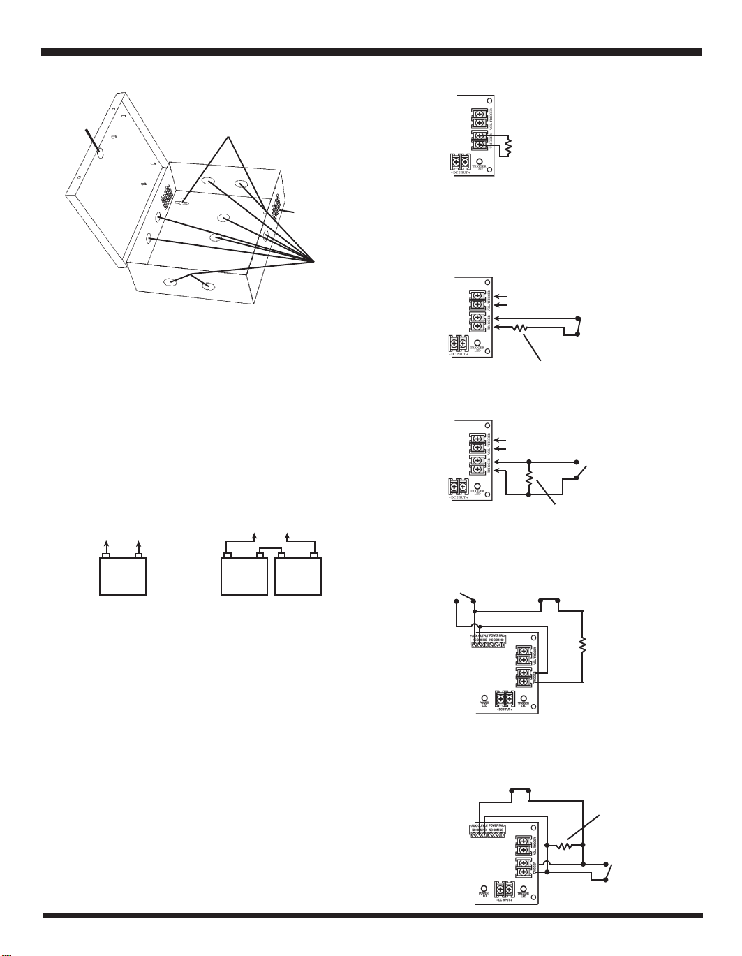
2. Locate the enclosure mounting holes. Using these holes as a
template, mark the location of the 4 screws on the wall with a
pencil. First fasten two
included) until the gap between the wall and the screw head is
approximately 1/4" (6mm). Hang the enclosure on the 2 screws
using the enclosure's upper screw holes and adjust the proper
location of the enclosure. Then securely fasten the upper and
lower screws. Use larger sized screws if backup batteries will be
placed inside the enclosure.
5
/32" x 1" (4 x 26mm) upper screws (not
Page 1
Page 2
Access Control Power Supply Installation Manual Access Control Power Supply Installation Manual
Knock-out
for optional
cam lock
FIG. 1
Enclosure
Mounting Holes
Ventilation
Holes
Cable &
Power
Knock-outs
NOTE: For concrete walls, first drill four holes on the concrete wall in
the location of the screws. Then insert a "plastic anchor" in each of the
holes before fastening the screws.
3. Set the desired DC output voltage (12 or 24 VDC) via DIP switch (see Fig.10).
4. Connect the back-up battery (not included) to the back-up battery
terminal (see Fig.2 & Fig.10). Check the voltage output reading of the
Power Distribution Module (PDM). If the “POWER LED” is ON, and if the
voltage reading of the PDM's five channel output is the same as that of
the back-up battery terminal's voltage reading, then this indicates that the
power supply is working properly. Disconnect battery after testing.
Fig. 2 – Back up battery configuration.
+
12 VDC
Battery
24 VDC
-
+
12 VDC
Battery
-
12 VDC
+
12 VDC
Battery
-
Fig. 3
2.2kΩ (EOL)
resistor
8. Follow the connection diagrams shown on Fig. 4~9 to trigger the PDM
from a wet and/or dry contact switch from the control station:
Fig. 4 – Momentary trigger wiring diagram for wet and / or dry N.C. switch.
DC voltage input from control station
N.C.
switch
2.2kΩ (EOL) resistor(supplied)
Fig. 5 – Momentary trigger wiring diagram for wet and / or dry N.O. switch.
DC voltage input from control station
N.O.
switch
2.2kΩ (EOL) resistor(supplied)
Fig. 6 – Latch trigger wiring diagram for wet and / or dry N.C. switch.
N.O. switch
for RESET
N.C. switch from access
control panel
5. Connect the power input wires of the access control devices or
accessories to the Power Distribution Module (PDM) (see Fig.10). Observe
correct polarity. For fail-secure devices, connect positive to terminals
marked "POS. OPEN LOOP" and negative to terminals marked "NEG."
For fail-safe devices, connect positive to terminals marked "POS. CLOSE
LOOP" and negative to terminals marked "NEG".
Maximum total current connected to all terminals must not exceed the
power supply's total current capacity (see Table 1).
6. Connect a visual or audio indicator device (such as siren or strobe light)
to the AC-fail and battery-fail / low battery supervision relays if needed
(see Fig.10). Use between 22AWG to 18AWG wire size.
7. Connect a visual or audio indicator device (such as siren or strobe light)
to the power fail supervision relay and Auxiliary output relay if needed
(see Fig.10). Use between 22AWG to 18AWG wire size.
IMPORTANT NOTE: If the "TRIGGER" terminal block
function is not going to be used, then a 2.2kΩ
resistor must always be connected to the "TRIGGER"
terminal block as shown below in Fig.3.
Page 2
2.2kΩ (EOL)
resistor (supplied)
Fig. 7 – Latch trigger wiring diagram for wet and / or dry N.O. switch.
N.C. switch
for RESET
2.2kΩ (EOL)
resistor (supplied)
N.0. switch from access
control panel
Page 3

Fig. 8 – Multiple PDM momentary trigger wiring diagram for wet and / or dry
N.O. switch.
For Additional
PDM if needed
DC voltage
Second
PDM
2.2kΩ
(EOL) resistor
(supplied)
First
PDM
input from
control station
2.2kΩ (EOL)
resistor (supplied)
N.O.
switch
IMPORTANT:
a. To avoid risk of electrical shock, the ground terminal of the
"AC INPUT" MUST be connected to earth via the power cord.
b. The included core clamp must be installed on the power cord as
shown below.
Clamp core
Fig. 9 – Multiple PDM momentary trigger wiring diagram for wet and / or dry
N.C. switch.
For Additional
PDM if needed
DC voltage
Second
PDM
2.2kΩ
(EOL) resistor
(supplied)
NOTE: Output LEDs on the PDM will turn ON when fuse
has been tripped.
First
PDM
input from
control station
2.2kΩ
(EOL) resistor
(supplied)
N.C.
switch
9. Double check connections to ensure everything is connected properly.
10. Connect the AC power (110~240VAC). The AC LED and DC LED on the
mainboard and the power LED on the PDM should turn ON to indicate the
power supply unit is working properly.
11. Connect the back-up battery wiring. Check the voltage output reading of
the PDM to ensure it is within the normal working range.
Table 1: Max. supply current chart
Model
EAP-5D5Q
Max. supply
current at
12VDC
5 Amp.
Max. supply
current at
24VDC
2.5 Amp.
Power cord
Programmable/Adjustable Features:
A. AC-failure Relay Output Delay Timer — Programmable AC-failure
relay delay timer can be set at 5 sec., 5 min. or 5 hr. using the DIP
switch. See Fig. 10. Default setting is at 5 sec.
B. 2.2k
Ω End-of-Line (EOL) resistor — End-of-line 2.2kΩ resistor for
AC-failure relay and battery-failure / low battery supervision relays
can be activated independently using the DIP switch. See Fig. 10.
C. Battery presence and low battery monitor — When the LB MODE
DIP switches are in the ON position, the power supply will monitor
the battery to verify if it has sufficient voltage to run the power
supply in case of AC power failure. It can take up to 5 minutes to
send a battery failure alert. The length of time the system will run
will be limited by the overall capacity and the age of the batteries
and the amount of load being drawn off the power supply. See
Fig. 10.
D. VR1 rotary knob for DC voltage output adjustment -- Use to increase
or decrease the voltage of the outputs. Measure voltage output at
the device located furthest from the power supply.
Table 2: Terminal Functions
Mainboard
Terminal Legend
A E N
BAT. FAIL
AC FAIL
-
BAT +
-
DC +
Functions
To connect 110~240 VAC power. ( "A" for active wire, "E" for earth or ground wire, and "N" for neutral wire)
Used to notify battery failure. Dry contact relay rated at 3Amp.@24VDC. If back-up battery is not connected properly or if voltage output falls below 10.8VDC for 12VDC
setting (or 21.6VDC for 24 VDC setting), the connected warning device will be activated.
Used to notify loss of AC power. Dry contact relay rated at 3Amp.@24VDC
If AC power is cut-off, the connected warning device will be activated.
Used to charge the back-up battery. Maximum charging current is 3.5 Amp.
12 or 24VDC output terminal from main board.
Page 3
Page 4

Access Control Power Supply Installation Manual
Power Distribution Module (PDM)
Terminal Legend
TRIGGER
Functions
Used to connect N.O. or N.C. input trigger signal (2.2kΩ EOL resisitor) from access control panel.
A short or open circuit will transfer power from "POS. CLOSE LOOP" to "POS. OPEN LOOP.
VOL. TRIGGER
POWER FAIL
AUX OUTPUT
-
DC INPUT +
Used to connect wet (5-30VDC) input trigger signal from access control panel.
A short or open circuit will transfer power from "POS. CLOSE LOOP" to "POS. OPEN LOOP.
U
sed to notify loss of DC power. Dry contact relay rated at 3Amp.@24VDC
If VDC input to the PDM is interrupted, the connected warning device will be activated.
Used to activate other auxiliary device when trigger signal is received from the "TRIGGER" or "VOL TRIGGER" terminals.
12 or 24 VDC input from main board.
FIG.10: Power Connections and Dip Switches for Mainboard & Power Distribution Module (PDM)
Five Fail-Safe &
Fail-Secure Fused
Outputs at 12 or 24VDC output
AC input
MainboardMainboard
Mainboard
MainboardMainboard
Auxiliary Output Relay
DC Power Fail Supervision
LB MODE
ON PRESENT
OFF FAIL
EOL RES
1 2
ON OΩ OΩ
OFF 2.2KΩ
AC FAIL Timer
1 2
5H OFF OFF
5m ON OFF
5s ON ON
V. OUT.
ON 24V
OFF 12V
1
Battery presence
OFF
and low battery
NO
ON
monitor DIP switch
OFF
ON
NO
End-of Line (EOL)
1 2
2.2kΩ resistor
DIP switch
NO
AC failure delay
1 2
timer DIP switch
ON
OFF
VR1 rotary knob for DC
output voltage range
adjustment
NO
ON
DIP switch for 12 or
24 VDC output selection
1
OFF
Back-up
battery terminal
DC output
terminal block
Terminal Block
Relay
PowerPower
Power
PowerPower
DistributionDistribution
Distribution
DistributionDistribution
Module (PDM)Module (PDM)
Module (PDM)
Module (PDM)Module (PDM)
Parts List
2 x Screws for the enclosure door
1 x Plastic cable clamp (to secure power cord)
1 x Nut (to fasten cable clamp)
1 x Plastic snap bushing
3 x Wires for back-up battery
(red, black, white)
1 x Spare glass fuse (for AC input)
1 x Spare 5A blade fuse
(for back-up battery input)
1 x Clamp core (for power cord)
1 x 6-ft. power cord with ground wire
Ω
resistor
1 x 2.2k
DC voltage input signal from
Access Control Station
or emergency switch
N.C. or N.O. input from
Access Control Station
or emergency switch
Note: If an overload occurs, such as the total current connected to the power supply exceeds the power supply's total current capacity, the
mainboard's voltage output will start to drop. The voltage drop will depend on the extent of the overload. The greater the overload the bigger the output
voltage drop. If the overload is extensive, the voltage output will become intermittent and the red LED will start flashing. When the overload is
removed, the mainboard will automatically restart normal output.
If an output short-circuit occurs, the mainboard will automatically shut the output down and the red LED will turn off. When the short-circuit is
removed, the mainboard will automatically come back on line.
The SECO-LARM® policy is one of continual development and improvement. For that reason, SECO-LARM reserves the right to change specifications without notice. SECO-LARM is not responsible for misprints.
WARRANTY: This SECO-LARM product is warranted against defects in material and workmanship while used in normal service for a period of one (1)
year from the date of sale to the original consumer customer. SECO-LARM’s obligation is limited to the repair or replacement of any defective part if the unit is
returned, transportation prepaid, to SECO-LARM.
This Warranty is void if damage is caused by or attributed to acts of God, physical or electrical misuse or abuse, neglect, repair, or alteration, improper or
abnormal usage, or faulty installation, or if for any other reason SECO-LARM determines that such equipment is not operating properly as a result of causes other
than defects in material and workmanship.
The sole obligation of SECO-LARM, and the purchaser’s exclusive remedy, shall be limited to replacement or repair only, at SECO-LARM’s option. In no event
shall SECO-LARM be liable for any special, collateral, incidental, or consequential personal or property damages of any kind to the purchaser or anyone else.
SECO-LARMSECO-LARM
SECO-LARM
SECO-LARMSECO-LARM
®
U.S.A., Inc., U.S.A., Inc.,
U.S.A., Inc., 16842 Millikan Avenue, Irvine, CA 92606
U.S.A., Inc., U.S.A., Inc.,
Tel: 800-662-0800 / 949-261-2999 Fax: 949-261-7326
Page 4
Website: www.seco-larm.com
@
E-mail: sales
Copyright 2011 SECO-LARM U.S.A., Inc. All rights reserved.
seco-larm.com
MiEAP-5D5QUS_1110.pmd
Order Part #764-034-2%
PITSW1
 Loading...