

Page 1

ENFORCER Quad-Photobeam Detectors
Also available from SECO-LARM:
E-960-D290Q
Twin Photobeam
Detectors
Range: up to 290' outdoors.
•
Lensed optics reinforce beam
•
strength and provide excellent
immunity to false alarms due to
rain, snow, mist, etc.
Weatherproof, sunlight filtering
•
case for indoor and outdoor
conditions.
Quick easy installation with built-
•
in laser-beam alignment system.
E-932-D33TBQ
E-932-S16RRQ
Flush-Mount Photobeam
Sensors
E-932-D33TBQ – Photoelectric
•
Through-Beam Sensor.
E-932-S16RRQ – Photoelectric
•
Reflective-Beam Sensor.
Suitable for entrances, hallways,
•
room in office or home.
Fits single-gang box.
•
Adjustable alignment angle from
•
o
horizonatally / vertically.
+/-15
E-9622-4B25
Curtain / Barrier Sensors
Available in 4, 6, 8 or 10 beams.
•
Range:25 ft. outdoor ,
•
•
•
•
50 ft. indoor.
Slim-line design 7/8" x 15/16”.
Weatherproof IP65 construction.
Triggers on breaking of any
single or 2 adjacent beams
(programmable).
®
ENF ORCER
SENSOR
MANUAL
Multi-Frequency
Quad Photobeam Detectors
E-964-Q660Q –
E-964-Q495Q – 495 ft. (150m) outdoors, 990 ft. (300m) indoors
E-964-Q330Q – 330 ft. (100m) outdoors, 660 ft. (200m) indoors
E-964-Q165Q – 165 ft. ( 50m) outdoors, 330 ft. (100m) indoors
660 ft. (200m) outdoors, 1320 ft.
(400m) indoors
WARRANTY: This SECO-LARM product is warranted against defects in material and workmanship while used
in normal service for a period of three (3) years from the date of sale to the original consumer customer.
SECO-LARM’s obligation is limited to the repair or replacement of any defective part if the unit is returned,
transportation prepaid, to SECO-LARM.
This Warranty is void if damage is caused by or attributed to acts of God, physical or electrical misuse or abuse,
neglect, repair, or alteration, improper or abnormal usage, or faulty installation, or if for any other reason
SECO-LARM determines that such equipment is not operating properly as a result of causes other than defects in
material and workmanship.
The sole obligation of SECO-LARM, and the purchaser’s exclusive remedy, shall be limited to replacement or
repair only, at SECO-LARM’s option. In no event shall SECO-LARM be liable for any special, collateral,
incidental, or consequential personal or property damages of any kind to the purchaser or anyone else.
NOTICE:
the SECO-LARM policy is one of continual development and improvement. For this reason, SECO-LARM reserves the
right to change specifications without notice. SECO-LARM is also not responsible for misprints or typographical errors.
Copyright © 2008 SECO-LARM U.S.A., Inc. All rights reserved. This material may not be reproduced or copied,
in whole or in part, without the written permission of SECO-LARM.
SECO-LARM's ENFORCER Twin Photobeam detector series are protected by the following patents:
U.S. pat. no. D485774 ; Taiwan pat. no. 89463 ; China pat. no. ZL0331103.0
Other international patents are pending.
SECO-LARMSECO-LARM
SECO-LARM
SECO-LARMSECO-LARM
16842 Millikan Avenue, Irvine, CA 92606
Tel: 800-662-0800 / 949-261-2999 Fax: 949-261-7326
12
The information and specifications printed in this manual are current at the time of publication. However,
®
U.S.A., Inc. U.S.A., Inc.
U.S.A., Inc.
U.S.A., Inc. U.S.A., Inc.
Website: www.seco-larm.com
E-mail: sales
MIE964-D_US_P0804u.pmd
@
seco-larm.com
PITSW3
SECO-LARM
Note: Products with model number that ends with "Q" or have a green “Q” sticker represents RoHS compliant products.
Page 2
ENFORCER Quad-Photobeam DetectorsENFORCER Quad-Photobeam Detectors
T ABLE OF CONTENTS
Introduction................................................... 2
Features ....................................................... 2
Overview....................................................... 3
Wiring Diagram............................................. 4
Choosing a Location..................................... 4
Running the Cable ..................................... 4
Multiple Sensor Sample Applications........... 5
Typical Installations..................................... 5
Wiring the Transmitter – Wall Mount.......... 6
Wiring the Transmitter – Pole Mount ......... 6
Wiring ......................................................... 6
Examples of Ways To Connect Sensors ... 7
Selectable 4-channel Beam Frequency .... 8
Receiver Detail........................................... 8
Beam Alignment Template ......................... 8
Beam Alignment ........................................ 9
Adjusting the Delay Time ......................... 1 0
Testing the Unit ........................................ 10
Specifications ........................................... 10
Dimensions............................................... 11
Troubleshooting ....................................... 11
Introduction:
The ENFORCER E-964-Q Series Quad-Photobeam Sensors are ideal for long-distance protection.
Four selectable beam frequencies allow for superior perimeter protection by eliminating crosstalk and
interference between multiple units. False alarms created by animals and falling leaves are minimized
by the sensor's detection method of all 4 beams simultaneously broken.
The E-964-Q Series of sensors is designed to work in even the most extreme conditions. A built-in
heater automatically turns on and off depending on the outside temperature. An environmental control
output senses a slow degradation in beam strength when weather conditions worsen preventing false
alarms.
Installation and alignment is quick and easy with the ENFORCER E-964-Q Series. The built-in laser
and visual alignment systems quickly and easily pinpoint the approximate mounting location for the
transmitter and aid in aligning the transmitter and receiver units once mounted. A beam strength
indicator clearly displays the strength of the beam at the receiver with 5 LEDs.
Features:
O
Four selectable beam frequencies to eliminate
interference between multiple units for
enhanced perimeter protection.
O
Audible beam alignment (buzzer).
O
Beam strength indicator (5 LEDs).
O
Environmental Output (Selectable N.O. or N.C.):
Signal is sent if a degradation in environmental
conditions is detected such as thickening fog to
prevent false alarms.
O
Built-in heater.
O
IP-55 ingress protection.
O
Lensed optics reinforce beam strength and
provide excellent immunity to false alarms due
to rain, snow, mist etc.
O
Automatic input power filtering with special
noise rejection circuitry.
O
Voltage testing points for fine tuning the beam
alignment.
O
Input voltage: 12-24V AC/DC.
O
Delay time adjustable for nearly all situations.
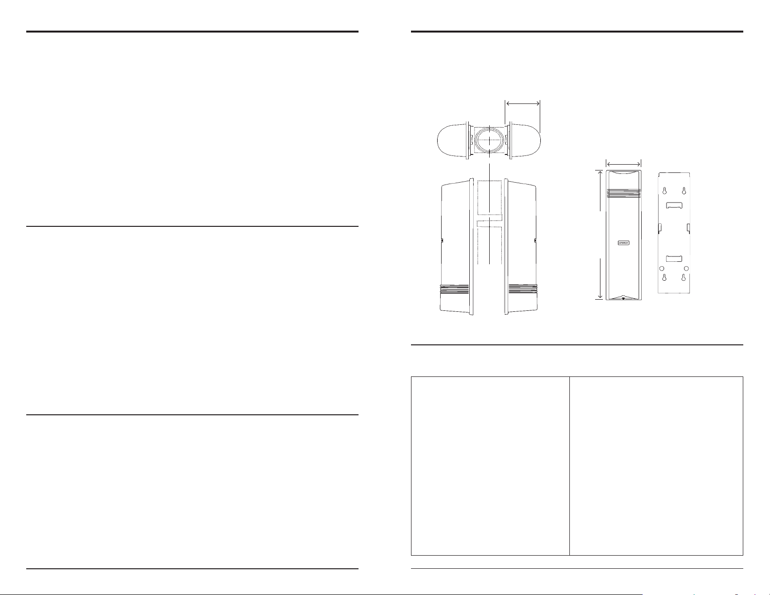
Fig. 15: Dimensions
411/32”
(110mm)
Upper
View
47/16”
43ST Pole Size
(113mm)
” (367mm)
4
/
1
15
Side View
Front View
Rear View
Troubleshooting:
Transmitter LED not lit
_________________________________________________________________________________________________________________________________
Receiver LED does not light when interrupted
_________________________________________________________________________________________________________________________________
Beams are interrupted and LED lights, but the
alarm does not trigger.
_________________________________________________________________________________________________________________________________
Signal LED continuously lit
_________________________________________________________________________________________________________________________________
Alarm trigger becomes erratic in bad weather
_________________________________________________________________________________________________________________________________
Frequent false alarm triggers
Make sure the input power to the transmitter is
12 to 24 VAC/VDC.
Check the input power to the receiver is 12 to 24
VAC/VDC.
Check the continuity of the wiring from the
receiver to the alarm.
Clear any obstacles between the transmitter and
receiver.
Clean the lenses of both units.
Check overall system installation.
Realign the lenses.
Adjust the response time.
Change location of transmitter and receiver.
2
SECO-LARM® U.S.A. SECO-LARM® U.S.A.
11
Page 3

ENFORCER Quad-Photobeam DetectorsENFORCER Quad-Photobeam Detectors
Adjusting the Delay Time
1. The delay time adjustment knob sets how long the beam can be
interrupted before triggering the alarm (see fig. 13):
a. A short delay time (high sensitivity) is suitable for catching fast moving
intruders, but more susceptible to false alarms.
b. A long delay time (low sensitivity) reduces false alarms, but fast
moving intruders may not trigger the sensor.
2. Adjust the knob to the site’s situation. You may need to make adjustments
later after the walk-through test.
Fig. 14:
Adjusting the
Delay Time
(300ms)
Testing the Unit
1. Power up the transmitter and receiver.
2. If the red alarm LED remains steady ON even when
the beam is not interrupted, re-adjust the alignment.
3. Walk between the transmitter and receiver to interrupt
the beams. Walk at various speeds, and adjust the
delay time adjustment knob as needed.
Table 4: Specifications
Model
Max. range (outdoor)
Max. range (indoor)
Current (Tx & Rx)
Current (Tx & Rx & heaters)
Input voltage
Delay time
Detection method
Selectable beam frequencies
Alarm output
Tamper output (Tx & Rx)
Environmental output
Beam-strength indicator
Signal LED (Rx)
Power LED (Tx & Rx)
Laser wavelength
Laser output power
Alignment angle
Operating temperature
Weight
Ingress protection
Case
Dimensions
* This is the minimum time interval between breaking of both beams which will trigger the output. Setting the interval longer will
reduce false alarms from birds or falling leaves, etc., while setting it shorter will detect faster moving objects.
E-964-Q165Q
165' (50m)
330’ (100m)
110mA
260mA
12~24 VAC/VDC (non-polarity)
50msec~700msec (variable)
All 4 beams simultaneously broken
Four (4) channels
Form "C" relay COM/N.O./N.C. 1A@125VAC/24VDC
NC switch, 1A @ 120VAC
Selectable N.O. or N.C. 1A@125VAC/24VDC
5 LEDs indicate signal strength from high to low
Red LED ON Green LED - illuminated when power is on
650nm
≤
5mW
Horizontal: ±90
-13~1310F (-250~ 550C)
5.7 lbs. (2.6kg)
IP55
PC Resin
1
15
/4" x 47/16" x 411/32" (387 x 113 x 110mm)
NOTE – The alarm will be triggered only if
both the upper and lower beams are
simultaneously interrupted.
IMPORTANT – Test the detector periodically
to ensure the alignment and delay time
settings are suitable for the site.
E-964-Q330Q
330’ (100m)
660’ (200m)
115mA
270mA
beam is broken or Tx and Rx out of alignment
0
Vertical: ±15
E-964-Q495Q
495’ (150m)
990’ (300m)
120mA
280mA
0
SECO-LARM
Fig. 1: Overview
Alignment laser
adjustment screw
700ms50ms
Green power LED
Power 12~24V AC/DC
E-964-Q660Q
660’ (200m)
1320’ (400m)
125mA
290mA
®
U.S.A. SECO-LARM® U.S.A.
indicator (5 LEDs)
Voltage output probes
adjustment screw
Alignment laser
On/Off switch for laser
IMPORTANT – Do not connect to power until the sensor is completely installed and the
Vertical
Alarm output
Beam strength
Tamper output
Vertical
(Receiver shown)
installation has been double-checked.
On/Off switch for laser
Viewfinder
Horizontal
adjustment grip
Red signal LED
NC/NO switch
On/Off
Environmental
output
}
Beam channel selection DIP
switches
Delay time (50ms~700ms)
Heater power
Environmental output
Horizontal
adjustment grip
Viewfinder for alignment
310
Page 4

ENFORCER Quad-Photobeam DetectorsENFORCER Quad-Photobeam Detectors
Fig. 2: Wiring Diagram
Receiver
Power AC/DC
12-24V
(non-polarized)
Alarm O/P
1A @
125VAC
/24VDC
T amper output
N.C. switch
1A @ 30VDC
(Max.)
N.C.
Com
N.O.
1
2
3
4
Heater
5
6
7
Environmental
output (NO/NC)
1A @ 125 V AC
/24VDC
Transmitter
Power AC/DC
12-24V
(non-polarized)
T amper output
N.C. switch
1A @ 30VDC
(Max.)
1
2
Heater
6
7
Choosing a Location
1. Find a suitable location for the receiver within wiring distance of a power supply and the alarm panel.
2. Establish a clear line-of-sight area between the receiver location and the transmitter location.
3. Make sure no trees or vegetation will cause false alarms during windy conditions.
4. Find locations away from standing water that could be splashed on to the receiver or the transmitter.
5. Do not mount the receiver where sunlight or bright lights shine directly into the unit.
6. Install at a distance of 32” to 39” (80 to 100 cm) above the ground for most situations. See fig. 3.
Running the Cable
Run a cable from the alarm control panel to the photobeam sensor. If burying the cable is required, make
sure to use electrical conduit. Shielded cable is strongly suggested. See Table 1 for maximum cable length.
Table 1: Cable Length
Model E-964-Q660Q
Wire Size
AWG22
AWG20
AWG18
AWG17
Note (1): Max. cable length when two or more sets are connected is the value shown in Table 1 divided by the no. of sets.
E-964-Q165Q E-964-Q330Q
12V 24V 12V 24V 12V 24V
320m
1,050ft.
550m
1,800ft.
800m
2,600ft.
980m
3,190ft.
2,800m
18,000ft.
4,800m
15,750ft.
7,200m
23,620ft.
8,800m
28,870ft.
280m
920ft.
450m
1,480ft.
700m
2,300ft.
850m
2,790ft.
2,400m
7,870ft.
4,200m
13,780ft.
6,200m
20,340ft.
7,600m
24,930ft.
E-964-Q495Q
200m
660ft.
350m
1,150ft.
500m
1,640ft.
590m
1,940ft.
1,600m
5,250ft.
3,000m
9,840ft.
4,200m
13,780ft.
5,200m
17,060ft.
12V 24V
110m
390ft.
170m
560ft.
250m
820ft.
310m
1,020ft.
2,950ft.
1,400m
4,590ft.
2,200m
7,220ft.
2,600m
8,530ft.
900m
Beam Alignment Procedure
1. Remove the sensor cover and turn On the top and
bottom lasers of both the transmitter and receiver.
There are a total of four lasers.
2. Adjust the transmitter's sensor unit vertically and
horizontally until the red dot is centered on the
receiver and the receiver’s signal LED turns Off.
3. Repeat step 2 for the receiver then turn Off the
lasers.
4. Look through the viewfinder on the transmitter’s
lower sensor and adjust it vertically and horizontally
until the receiver is clearly seen in the viewfinder.
5. Repeat step 4 for the receiver.
6. Turn On the beam alignment buzzer DIP switch
(fig. 9). If the beams are not aligned the buzzer will
sound.
7. Cover the top sensor on the receiver with the
included template (as shown in fig. 10). Adjust the
horizontal angle of the receiver’s lower sensor
vertically and horizontally until the buzzer stops
sounding. Repeat while covering the lower sensor
and adjusting the top sensor.
8. Turn the buzzer Off.
9. Turn On the beam strength Indicator DIP switch
(fig. 9). If the beams are not aligned, the indicator
will display little or no beam strength, see fig.12.
10.Cover the top sensor on the receiver. Adjust the
horizontal angle of the receiver’s lower sensor
vertically and horizontally until the beam strength
indicator displays a strong signal. Repeat while
covering the lower sensor and adjusting the top
sensor.
11.Turn the beam strength indicator Off.
Fine Tuning
The most accurate way to align the transmitter and
receiver is to measure the voltage using the voltage
output jack.
1. Set the range of a multimeter to 0~10VDC.
2. Insert the red probe into the (+) terminal and the
black probe into the (-) terminal.
3. Using Table 3, adjust the receiver’s sensors
vertically and horizontally until the best possible
voltage output is achieved.
Table. 3: Voltage Output
Voltage Output
Alignment Quality
<1.6 1.6~2.0V 2.0~2.4V 2.4~2.8V 2.8~3.2V >3.2V
No Signal Bad Poor OK Good Strongest
Fig. 11:
Horizontal and Vertical
Sensor Adjustment
Vertical
Adjustment
Screw
Horizontal
Adjustment
Finger Grips
View Finder
The transmitter and receiver sensor units
can be adjusted ±15° vertically and ±90°
horizontally once the unit is mounted and
power is connected.
Fig. 12:
Beam Strength Indicator
Strongest
Good
OK
Poor
Bad
No Signal
Fig. 13: Using a Multimeter
for Fine Tuning
SECO-LARM® U.S.A. SECO-LARM® U.S.A.
94
Page 5

ENFORCER Quad-Photobeam DetectorsENFORCER Quad-Photobeam Detectors
3
3
3
3
3
3
3
3
3
3
3
3
3
3
3
3
3
3
3
3
3
3
3
3
3
3
3
3
3
3
3
3
3
3
3
3
3
3
3
3
323
Selectable 4-channel beam frequency:
The sensor beam frequency can be set at different
levels on-site to avoid interference from other
photobeam sensors nearby. To select between four
different beam frequencies, adjust the beam
channel switch of the transmitter side and receiver
side. See pg. 3, fig. 1 for switch location and table 2
for switch position.
Fig. 9: Receiver Detail
Table 2: Channel
Beam Frequency Selection Chart
CH4
Freq. channel CH1
NO
Switch position
Important
12
– The transmitter and receiver
must be programmed to the same channel.
DIP Switch Channel Selector
Beam Alignment Buzzer Switch
Beam Alignment Strength Indicator Switch
CH2
12
CH3
NO
12 12
Multiple sensor sample applications
1. Long distance series application.
Tx
Channel #1
Rx
NO NO
Rx
Channel #2
Tx
2. Two layer (double stacked) applications.
Channel #1
Tx
Rx
Channel #4 Channel #3 Channel #2
Tx
Rx
Channel #2 Channel #3
Rx
Tx
Rx
3. Perimeter security application.
Rx
Rx
Tx
Channel #3
Channel #1
Tx
Channel #2
Channel #4
Tx
Rx
Rx
Tx
Channel #3 Channel #4
Tx
Rx
Tx
Tx
Tx
4. Single pair multiple layer application.
Tx Rx
Tx
Tx Rx
Tx
Rx
Rx
Channel #4
Rx
Channel #1
Rx
Channel #1
Channel #2
Channel #3
Channel #4
TxRx
Tx
Tx
Rx
Rx
Fig. 3: Typical Installations
2
2
2
2
2
2
2
2
2
2
2
2
2
2
2
2
2
2
2
2
2
2
2
2
2
2
2
Fig. 10: Included Beam Alignment Template:
Use the included SECO-LARM template to aid in aligning
the transmitter and receiver.
Side Views
32" to 39"
T op V iews
8 5
SECO-LARM® U.S.A. SECO-LARM® U.S.A.
2
2
2
2
2
2
2
2
2
2
2
2
2
2
Page 6

ENFORCER Quad-Photobeam DetectorsENFORCER Quad-Photobeam Detectors
Wiring the Transmitter – Wall Mount
1. Remove the cover. Remove the screw under the
lens unit in order to detach the mounting plate.
See fig. 4.
2. If the sensor wiring comes from inside the wall –
Break a hole in the mounting plate’s rubber
grommet, and pull the cable through the
grommet’s hole. Then run the cable through the
hole near the bottom of the sensor unit so it
comes out the front. Using two of the included
mounting screws, attach the mounting plate to the
wall. Then reattach the sensor unit to the
mounting plate, connect the wires, and snap on
the cover. See fig. 5.
3. If the sensor wiring is run along the surface of the
wall – There are four plastic knockouts on the
back of the sensor unit, two on top and two on
bottom. Break out the appropriate knockout, and
pull the wiring through the knockout. Then run the
wiring through the hole near the bottom of the
sensor unit so it comes out the front. Using two of
the included mounting screws, attach the
mounting plate to the wall. Then reattach the
sensor unit to the mounting plate, connect the
wires, and snap on the cover. See fig. 6.
Wiring the Transmitter
– Pole Mount
(NOTE – Pole mounting bracket included.)
1. Remove the cover. Remove the screw under
the lens unit in order to detach the mounting
plate. See fig. 4.
2. Break a hole in the mounting plate’s rubber
grommet, and pull the cable through the
grommet’s hole. Then run the cable through
the hole near the bottom of the sensor unit so
it comes out the front. Use the included
mounting bracket to mount to the pole. Then
reattach the sensor unit to the mounting plate,
connect the wires, and snap on the cover.
See fig. 7.
Wiring (fig. 8)
1. Screw the wires tightly to avoid slipping off the
terminals, but not so tight that they break.
2. Screws on terminals which are not used
should be tightened.
3. Grounding may be necessary, depending on
the location.
Fig. 4:
Remove the
Transmitter
cover
Fig. 5:
Wall Mount,
Wire from
Inside Wall
Fig. 6:
Wall Mount,
Wire Runs
Along Wall
Fig. 7:
Pole Mount
– or –
Fig. 8: Examples of Possible Ways To Connect One or More Sensors
Example connection 1 - Standard
}
Power
N.C. Alarm
}
signal
Control panel
(12~24VAC/VDC)
Tx Rx
Example connection 2 - In-line Single Channel
}
Power
N.C. Alarm
}
signal
Tx
Example connection 3 - Dual Sensors, Separate Channels
Tx
Example connection 4 - Two stacked
Rx
Tx
Ch1
Tx
Ch2RxCh2
Rx
Tx
Tx
Rx
Ch1
Rx
Rx
Control panel
(12~24VAC/VDC)
}
Power
N.C. Alarm
}
(ch. 1)
N.C. Alarm
}
(ch. 2)
Control panel
(12~24VAC/VDC)
}Power
}Alarm signal
Control panel
(12~24VAC/VDC)
6 7
SECO-LARM® U.S.A. SECO-LARM® U.S.A.
 Loading...