

Page 1
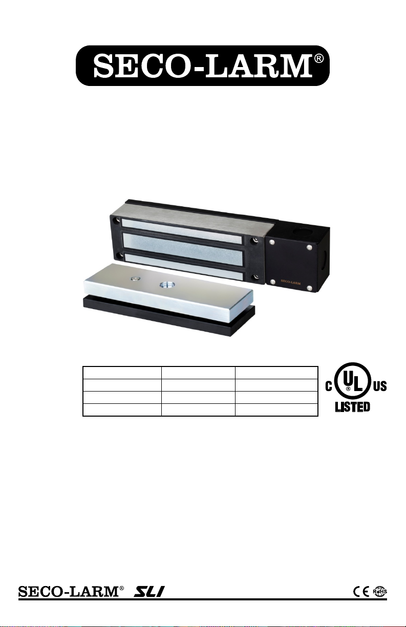
Electromagnetic Gate Lock
Manual
Model
Mounting type
Holding force
E-942FC-1K3SQ
Face
1,200-lb (544kg)
E-946FC-1K2SQ
Side
1,200-lb (544kg)
E-942FC-600SQ
Face
600-lb (272kg)
• For most types of outdoor sliding and
• Water- and vandal-resistant attractive
*Maglock Only
E-942FC-1K3SQ Shown
w/ Weldable Bracket
swinging electric gates
• Includes a magnetic lock with brackets for
armature and magnet
• Can be welded or bolted directly to gate
• Brackets are zinc-plated for corrosion
resistance
• Black finish to match most gates
stainless-steel finish
• Maintenance-free, factory-sealed design
• Fail-safe operation (releases if power is
removed)
• Mount vertically or horizontally
• Four knockouts on junction box
• Adapter and mounting hardware included
Page 2
SECO-LARM Electromagnetic Gate Lock with Weldable Bracket
1x Maglock brack et
1x
1x
1x
1x
2x Large steel washers
1x Rubber washer
1x Allen wrench for junction box
1x Security screw
1x
1x
2x
1x
Specifications:
E-942FC-1K3SQ, E-946FC-1K2SQ
Operating voltage
12/24 VDC
Holding force
1,200-lb (544kg)
Current
draw
12V
500mA
24V
250mA
Weight (approx.)
Bracket
4.6-lb (2.1kg)
cUL, UL, CE, RoHS
(magnetic lock only)
E-942FC-600SQ
Operating voltage
12/24 VDC
Holding force
600-lb (272kg)
Current
draw
12V
500mA
24V
250mA
Weight (approx.)
Bracket
3.95-lb (1.8kg)
cUL, UL, CE, RoHS
(magnetic lock only)
Parts List:
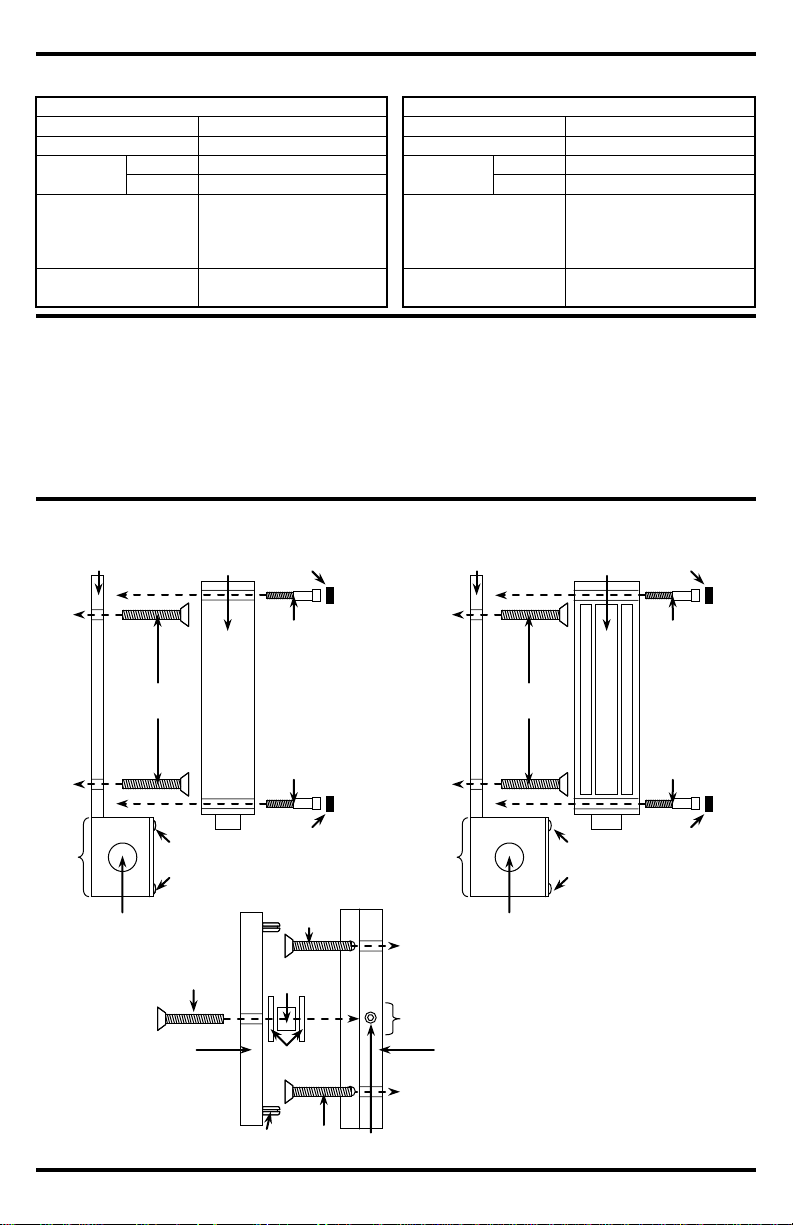
Mounting Diagram:
*E-942FC-600SQ requires o nly 1pc
Maglock brack et
Electromagnet
No weld
area
Anti-tamper
Junction box
Mounting bolts
Junction box
Mounting
Mounting
Anti-tamper
E-942FC-1K3SQ,
E-946FC-1K2SQ
No weld
area
Armature plat e
Armature bracket
Armature screw
Rubber
washer
Large steel
Mounting bolts
Mounting bolts
Guide pin
Security screw
Maglock brack et
Electromagnet
No weld
Anti-tamper
Junction box
Mounting bolts
Junction box
Mounting
Mounting
Anti-tamper
*2x Mounting screws/Anti-tamper caps (E-942FC-600SQ only)
Armature mounting
All models
Total
Maglock & armature
15.9-lb (7.75kg)
11-lb (5kg)
Total
Maglock & armature
10.4-lb (4.75kg)
6.4-lb (2.9kg)
Certifications
Certifications
Armature bracket
Electromagnet
Armature plate
Armature screw
4x Junction box screws
4x Mounting screw s*
4x Anti-tamper caps*
2x Guide pins
AC Pigtail connector
DC Pigtail connector (EVA-M5521-3)
Wire connectors
Power supply
caps x 2*
caps x 2
screws x 2*
screws x 2
(optional)
area
2 SECO-LARM U.S.A., Inc.
screws x 4
E-942FC-600SQ
(Face Mount)
screws x 2*
caps x 2*
(optional)
washers
(optional)
(optional)
screws x 4
(Side Mount)
screws x 2
caps x 2
Page 3

1. Mount the electromagnet. In most cases, the position of the electromagnet will determine the location of
2.
Weld the armature bracket with
between the armature and the bracket. This will allow the armature to pivot slightly around the
3.
4.
5.
6.
Installation:
IMPORTANT
connection will void warranty.
24VDC
24VDC
GND
Red
White
Black
Green
12VDC
12VDC
GND
Red
White
Black
Green
Wiring Diagram:
(Default setting)
SECO-LARM Electromagnetic Gate Lock with Weldable Bracket
Operation
Operation
Damage caused by i mproper
the armature plate. Make sure there is space to run the cable.
a. Tack weld bracket into place. (Tack weld only).
b. Dismount the electromagnetic lock from the bracket. Warning: Failure to remove
electromagnetic lock will result in severe damage to lock. Weld 3 or 4 beads about 1” apart.
Make sure not to weld the junction box. (See mounting diagram for “No Weld” areas).
c. Remount the electromagnetic lock.
Mount the armature:
a. Once the electromagnet is mounted, determine the armature bracket location and tack weld into
place (Tack weld only.)
b. Dismount the armature plate from the bracket. Warning: Failure to remove the armature plate
from the bracket will damage the armature and rubber washer.
3 or 4 beads about 1” apart. Make sure not to weld near the set screw hole. (See mounting
diagram for “No Weld” areas).
c. Remount the armature.
i. Put one rubber washer between two steel washers, and place them over the armature screw
armature screw in order to compensate for gate misalignment.
ii. Make sure the guide pins are inserted into guide holes to prevent the armature from spinning.
iii. Do not overly tighten the armature against the bracket. The armature must be able to pivot
around the armature screw.
Run the wires. The goal is to keep as little of the wires exposed as possible.
a. Run the wires into an out-of-sight location as close as possible to the electromagnet.
b. Use standard armored cable to prevent the wires from being cut between the electromagnet and
the out-of-sight location.
Connect the wires. Note: Unit is prewired for 12V operation. See Wiring Diagram (page 3) for more
information.
a. For 12V operation – connect the red and white wires to +12VDC, and the black and green wires to
ground.
b. For 24V operation – connect the red wire to +24VDC, the green wire to ground, and then tie the
white and black wires together and insulate.
IMPORTANT: Damage caused by improper connection will void warranty.
Test the unit.
Insert the tamper caps into the mounting screw access holes of the electromagnet. This should be the
last step, as once the tamper caps are in place, they are difficult to remove.
SECO-LARM U.S.A., Inc. 3
Page 4

SECO-LARM Electromagnetic Gate Lock with Weldable Bracket
NOTICE:
However, the
SECO
right to
change specifications without notice.
Copyright © 2014
This material may not be reproduced or copied, in whole or
in part, withou
WARRANTY:
This SECO-LARM product is warranted against defects in material and workmanship while used in normal
service for the lifetime of the product
replacement of any defective part if
the unit is returned, transportation prepaid, to SECO
This Warranty is void if damage is caused by or attributed to
acts of God, physical or electrical misuse or abuse, neglect, repair or alteration, improper or abnormal usage, or faulty
installation, or if for any other reason SECO-LARM determines that such equipment is not operating properly as a result of
causes other than defects in material and workmanship.
exclusive
remedy, shall be limited to the replacement or repair only, at SECO
LARM be liable
for any special, collateral, incidental, or consequential personal or property damage of any kind to the purchaser or anyone
else.
SECO-LARM
®
U.S.A., Inc.
16842 Millikan Avenue, Irvine, CA, 92606
Website: www.seco-larm.com
Phone: (949) 261-2999 | (800) 662-0800
Email: sales@seco-larm.com
Order Part # 764-024-3%
MiE-94xFC-xxxSQ_140515.docx
• Check that the wires are secure
Check that the unit is wired correctly
• Check that the electromagnet and armature plate are
• The electromagnet is fitted with a metal oxide varistor to
Troubleshooting:
Maintenance:
1. Clean the contact surfaces of the electromagnet or armature plate with a soft cloth and non-abrasive,
2.
3.
4.
UL CERTIFICATION: The E-946FC-1K2Q, E-942FC-1300, and E-942FC-600 electromagnetic locks conform to
UL/10B “Fire Tests of Door Assemblies” and UL/10C “Positive Pressure Fire Tests of Door Assemblies” for swinging door
assemblies. They are also classified in accordance with the Uniform Building Code standa
The gate does not lock
• Check that the power supply is connected and operational
•
properly aligned
The gate locks, but can be easily
forced open
• Check that the contact surfaces of the electromagnet and
armature plate are clean and free from rust
• Check the power leads with a meter, and make sure the
correct voltage is present
There is a delay in the gate releasing
prevent interference, so do not install a secondary diode
non-corrosive cleaner.
Apply a light coat of a silicon lubricant to both contact surfaces and wipe away the excess to prevent rust
buildup.
Check that the armature plate is securely attached to the bracket, yet can pivot slightly around the
armature screw.
Check that the electromagnet is securely attached to the bracket.
rd 7-2.
The information and specifications printed in this manual are current at the time of publication.
-LARM policy is one of continual development and improvement. For this reason, SECO-LARM reserves the
4 SECO-LARM U.S.A., Inc.
SECO-LARM U.S.A., Inc. All rights reserved.
t the written permission of SECO-LARM.
. SECO-LARM’s obligation is limited to the repair or
-LARM.
The sole obligation of SECO-LARM and the purcha ser’s
-LARM’s option. In no event shall SECO-
SECO-LARM is also not r esponsible for m isprints or typographical errors.
PITSW1
 Loading...