

Page 1

Note: Model numbers that end with “Q” or t hat have a round green “Q” sticker signify RoHS-compliant products.
Electromagnetic Gate Locks
• Now with face and surface mounting
• Attractive stainless-steel housing
Model
Holding Force
E-946FC-600Q
600-lbs (271kg)
E-946FC-1K2Q
1,200-lbs (544kg)
with Face or Surface Mounting
Manual
• For sliding or swinging gates
• Water resistant and vandal resistant
• Maintenance-free, factory-sealed design
• Dual-threaded conduit fitting
• Dual voltage: 12/24 VDC Operation
• No residual magnetism
• MOV Surge protection
• Complete mounting hardware included
Page 2
SECO-LARM Electromagnetic Gate Locks with Face or Surface Mounting
Specifications:
Parts List:
Model
E-946FC-600Q
E-946FC-1K2Q
Holding force
600-lb (271kg)
1,200-lb (544kg)
Operating voltage
12VDC or 24VDC
Current
draw
12VDC
500mA
24VDC
250mA
Operating temperature
14°~131° F (-10°~55° C)
8”x111/16”x19/16”
(203x43x40 mm)
811/16”x21/2”x19/16”
(220x63x40 mm)
Armature
plate
71/4”x15/8”x9/16”
(185x41x14 mm)
71/4”x23/8”x5/8”
(185x61x16 mm)
Weight (approx.)
6-lb (2.7kg)
11-lb (5kg)
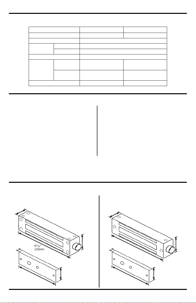
Dimensions:
*When using the optional Z-bracket, do not use the door spacer and the sexnut bolt. Also, replace the
armature screw with the short armature screw included with the bracket, or cover the exposed end of the long
screw with the nut.
E-946FC-1K2Q
E-946FC-600Q
E-946FC-1K2Q
E-946FC-600Q
811/16”
(220mm)
21/2”
(63
19/16”
(40
23/8”
(6
71/4”
(185mm)
5
/8”
(16mm)
15/8”
(4
71/4”
(185mm)
9
/16”
(14mm)
8”
(203mm)
111/16”
(43mm)
19/16”
(40mm)
1x
Electromagnet
1x
Armature plate
2x
Metal washers
1x
Rubber washer
1x
Sexnut bolt
1x
Armature screw
12x
Tamper caps
1x
Hex wrench
4x
Long hex screws
mounting)
4x
Short hex screws
(for face mounting)
1x
Blind nut tool
4x
Blind nuts
2x
Long guide pins
2x
Short guide pins
1x
Electromagnet
1x
Armature plate
2x
Metal washers
1x
Rubber washer
1x
Sexnut bolt
1x
Armature screw
6x
Tamper caps
1x
Hex wrench
2x
Hex screws
1x
Blind nut tool
2x
Blind nuts
2x
Guide pins
Magnet
Dimensions
(for surface
mm)
1mm)
2 SECO-LARM U.S.A., Inc.
mm)
1mm)
Page 3
SECO-LARM Electromagnetic Gate Locks with Face or Surface Mounting
Overview:
E-946FC-600Q
Installation Applications:
Single-swing gate
Sliding gate
E-946FC-1K2Q
Tamper cap
Electromagnet
Electromagnet
Tamper cap
Double-swing gate
For surface
mounting*
For surface
mounting
For surface
mounting
For surface
mounting
For face
mounting
For face
mounting
For face
mounting
For face
mounting
*NOTE: Each installation will use either face mounting OR surface mounting. No inst al l at i on wil l use both. For more information on which type of mounting
*NOTE: Each installation will use either face mounting OR surface mounting. No inst al l at i on wil l use both. For more information on which type of mounting
method to use, please see page 5, Installation.
Sexnut bolt
Sexnut bolt
Guide pin
Steel washer
Rubber washer
Armature screw
Steel washer
Guide pin
Steel washer
Rubber washer
Armature screw
Steel washer
*
*
*
*
method to use, please see page 5, Installation.
*
*
*
SECO-LARM U.S.A., Inc 3
Page 4

SECO-LARM Electromagnetic Gate Locks with Face or Surface Mounting
Wiring Diagram:
Wire Gauge @ 500mA
20
18
18
18
16
14
14
12
10
--
--
24VDC Minimum Wire Gauge:
12VDC Minimum Wire Gauge:
For a complete chart, please visit www.seco-larm.com.
Optional SECO-LARM Electromagnetic Lock Accessories:
Maximum Distance from Power Source to Electro magnetic Lock:
12VDC
IMPORTANT:
Damage
by improper
connection will
void warranty.
24VDC
Description
Z Brackets
L Brackets
E-946FC-600Q
E-942F-600/Z
Not available
E-946FC-1K2Q
E-942F-1300/ZQ
E-946F-1K2/LQ
Red
White
Black
Green
12 VDC
GND
24 VDC
GND
Red
White
Black
Green
caused
Wire Length 25ft 50ft 75ft 100ft 150ft 200ft 250ft 300ft 400ft 500ft 1000ft
Wire Length 25ft 50ft 75f. 100ft 150ft 200ft 250ft 300ft 400ft 500ft 1000ft
Wire Gauge @ 250mA 24 24 22 20 18 18 16 16 14 14 14
4 SECO-LARM U.S.A., Inc.
Page 5

SECO-LARM Electromagnetic Gate Locks with Face or Surface Mounting
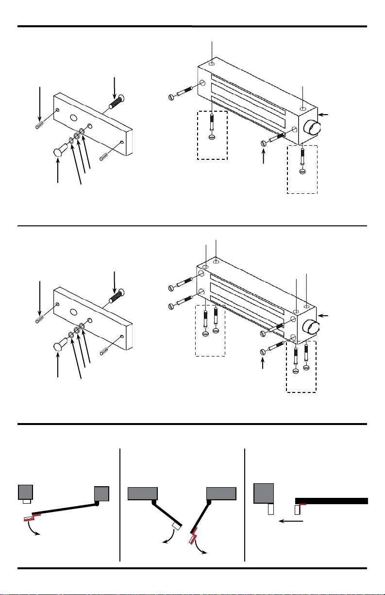
1. Determine type of gate:
when closed. In this case, a typical installation has the electromagnet face mounted to
Z bracket.
Installation:
b. Double-swing gate: Two gates swing in the same direction when activated. The
c. Sliding gate: The gate slides instead of swings away from a fixed gate post. In this
Z Bracket
Electromagnet
Armature plate
Armature plate
Electromagnet
Z Bracket
Armature plate
Install
electromagnet on
the side that will
close
Install Z
bracket on
the side that
will
Armature plate
Electromagnet
Z Bracket
Electromagnet
Armature plate
L Bracket
Electromagnet
Armature plate
L Bracket
Note: An L bracket may also be used as a spacer for the electromagnet if the electrom agnet and arm at ure pl at e are not aligned properly.
a. Single-swing gate: Gate swings on one end, and comes to rest on a fixed gate post
the gate post, and the armature plate connected to the free end of the gate with a
electromagnet is fixed to the free end of one gate, and the armature plate is fixed to
the free end of the other via a Z bracket. It is important to coordinate the swing of the
gates to prevent the armature plate from closing before the magnet.
open first
first
case, surface mount the electromagnet to the gate post and use an L bracket to
mount the armature plate perpendicular to it.
SECO-LARM U.S.A., Inc 5
Page 6

SECO-LARM Electromagnetic Gate Locks with Face or Surface Mounting
2. Mount the electromagnet. In most cases, the position of the electromagnet will determine the
Installation, continued:
Surface mounting
(E-946FC-600Q shown)
Face mounting.
(E-946FC-600Q shown)
Allen wrench
Hex screw (M6x30 thread)
Hex tool
Door header
Blind nut
Hold with wrench or vice
grip while turning hex screw
Washer
location of the armature plate. Make sure there is space to run the cable.
a. Tape the template to the
appropriate location.
b. Drill four (E-946FC-1K2Q) or two
(E-946FC-600Q) 9.5mm (
holes, one for each short hex
screw. IMPORTANT: The holes
must be 9.5mm (
larger.
c. Insert a blind nut in one of the
d. Put the washer on the M6x30
e. Use a wrench or vice-grip to tightly
f. Remove the screw.
g. Repeat steps c through f for the
h. Push hex screws into each of the
3
9.5mm (
screw. Then put the hex tool on the
screw. Then turn the screw by
hand into the blind nut.
hold the hex tool. Then use the
included Allen wrench to slowly
tighten the screw until it does not
turn any further. This compresses
the blind nut so that it remains
permanently fixed in the hole.
other blind nuts.
screw holes in the electromagnet.
Use the Allen wrench to tighten the
screws into the blind nuts.
3
/8”) holes.
3
/8”)
/8”). No smaller or
6 SECO-LARM U.S.A., Inc.
Page 7

SECO-LARM Electromagnetic Gate Locks with Face or Surface Mounting
3. Mount the armature plate. Once the
” on the inside. Use the appropriate
Installation, continued:
Armature plate
Z Bracket
Armature plate
L Bracket
electromagnet is mounted, determine the
correct position of the armature plate. Use the
appropriate L bracket or Z bracket to position
the armature plate so that it will lay against the
electromagnet when activated. However, leave
a slight gap between the two so that the
armature plate does not slam against the
electromagnet when the gate is closed.
a. Place the steel and rubber washers
4. Run the wires. Keep the wiring concealed.
5. Connect the wires and test the unit. See Wiring Diagram on pg. 4 for more information.
6. Insert the tamper caps into the mounting screw access holes of the electromagnet.
over the armature screw between the
armature and the bracket (see page 3,
Overview). This will allow the armature
to pivot slightly around the armature
screw to compensate for gate
misalignment.
b. Make sure the guide pins are inserted
loosely into guide holes to prevent the
armature from spinning.
c. Tighten the sexnut enough so the armature can withstand the force of someone
attempting to pry the gate open while the electromagnet is engaged.
d. Do not tighten the armature against the bracket. The armature must be able to pivot
slightly around the armature screw.
a. Run the wires into an out-of-sight location as close as possible to the electromagnet.
Run them inside hollow posts if possible.
b. Use standard armored cable to prevent the wires from being cut between the
electromagnet and the out-of-sight location.
c. The conduit fitting on the end is 3/4” outside and 1/
fitting if using conduit.
2
NOTE: This should be the last step, as once the tamper caps are in place, they are difficult to
remove.
SECO-LARM U.S.A., Inc 7
Page 8

SECO-LARM Electromagnetic Gate Locks with Face or Surface Mounting
LIMITED LIFETIME WARRANTY:
LARM product is warranted against defects in material and workmanship w hile used
in normal service for the lifetime of the product. SEC O
nt of any defective part
if the unit is returned, transportation prepaid, to SECO
costs or charges for removal, install ation, or reinstallation. This Warranty is void if damage i s caused by or attributed to acts of God,
physical or electr ical misuse or abuse, neglect, repair, or alteration, improper or abnormal usage, or faulty instal lation, o
other reason SECO
material and work m anship. The sole obl i gation of SECO
replacement or repair only at SECO
al, collateral, incidental, or
consequential personal or propert y damages of any kin d to the purchaser or anyone else. This lim ited lifetime warrant y is for
products sold and i nstalled in the United States and Canada. For all other countries the warranty i
NOTICE:
SECO
specifications wi thout notice. SE C O
Copyright © 2014 SECO-LARM U.S.A., Inc. All rights reser ved. This material may not be reproduced or copied, in whol e or in part,
without the writ
SECO
16842 Millikan A venue, Irvine, CA 92606
Tel: 800
PITGW1
MiE-946FC-xxxQ_140610.docx
Troubleshooting:
• Check that the electromagnet and armature plate are properly aligned.
electromagnet to VAC.
Maintenance:
1. Clean the contact surfaces of the electromagnet or armature plate with a soft cloth and
The gate does not lock.
The gate locks, but can be
easily forced open.
• Check that the wires are secure.
• Check that the power supply is connected and operating.
• Check that the unit is wired correctly.
• Check that the contact surfaces of the electromagnet and armature
plate are clean and free from rust.
• Check the power leads with a meter, and make sure the correct
voltage is present.
• Make sure that power supply is 12/24 VDC. Do not connect the
There is a delay in the
gate releasing.
• The electromagnet is fitted with a metal oxide varistor to prevent
interference, so do not install a secondary diode.
non-abrasive, non-corrosive cleaner.
2. Apply a light coat of a silicon lubricant to both contact surfaces and wipe away the excess to
prevent rust.
3. Check that the armature plate is securely attached to the door, yet can pivot slightly around the
armature screw.
4. Check that the electromagnet is securely attached to the gate or post.
-LARM policy is one of continual devel opment and improvement. For this reason, SECO-LARM res er ves the right to change
-LARM
-662-0800 / 949-261-2999 Fax: 949-261-73 26 E-mail: sales@seco-larm.com
8 SECO-LARM U.S.A., Inc.
-LARM determi nes that such equipment is not operati ng properly as a result of causes other than defects in
The information and specificati ons printed in this man ual are current at the t ime of publication. However, the
ten permission of SECO-LARM.
®
U.S.A., Inc.
This SECO-
-LARM’s option. In no event shall SEC O-LARM be liable for any speci
-LARM is also not responsible for mispri nt s or typographical errors.
Website: www.seco-larm.com
-LARM’s obligation i s l imited to the repair or r eplaceme
-LARM. Under no circumstances will SECO-LARM be responsible for a ny
-LARM, and the purchaser’s exclusi v e remedy, shall be limited to
s 1 (one) year.
r if for any
 Loading...