

Page 1

SEC
SEC America, LLC
Model 822 PS Pump Sentry
Model 1622 PS Pump Sentry
Owner's Manual
Sept. 4, 2014
1
Page 2

Index
Page
How Pump Sentry Works……………………………..…….. 3
Important Safety Instructions…………………………….... 4
Safety Warnings……………………………………………… 5
Battery Precautions………………………………………….. 6
Battery Box……………………………………………………. 8
Installation Location…………………………………………. 8
Making Connections…………………………………………. 9
Installation Test………………………………………………. 9
Changing the Battery………………………………………… 10
Charger Functions.…………………………………………… 11
Uninterruptible Power Indicator …………………………… 11
Fan Operation ………………………………………………… 11
How to Discern when Pump Sentry
is Operational in Back Up Mode …………………………… 13
How to Discern when Pump Sentry
is Operational in Standby Mode …………………………... 13
Fuses …………………………………………………………… 13
Audible Alarm …………………………………………………. 13
Warranty……………………………………………………….. 14
2
Page 3
Pump Sentry
Models 822 PS & 1622 PS
INSTALLATION INSTRUCTIONS
The Pump Sentry is an innovative power station designed to operate your
pump during a power outage. When properly installed, it will provide many
years of reliable service.
To ensure that the Pump Sentry is optimally used and properly connected,
we recommend its installation be made by a licensed electrician or fully
qualified professional. Read these instructions completely and follow
directions carefully.
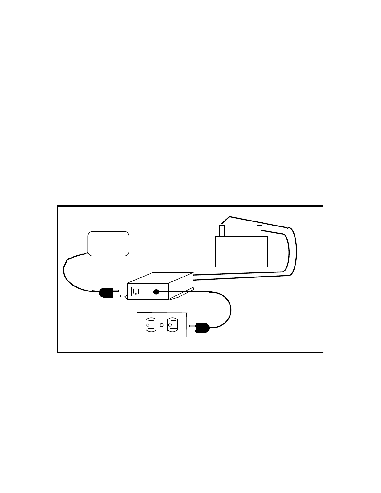
Appliance
1622PS/822 PS
AC Utility Power
How The Pump Sentry Works
When electricity is present, the Pump Sentry charges a 12-volt battery and
surveys the power line. At the instant that a power failure occurs, the Pump
Sentry converts the energy stored in the battery to AC power to operate your
pump. When AC utility power is restored, the Pump Sentry automatically
switches your pump back to AC utility power, recharges the battery, and
monitors the power line.
+ -
12 Volt
Battery
Figure 1
3
Page 4

While the Pump Sentry is a sophisticated electronic device, it should not be
expected to perform beyond its limitations, and extreme care should be taken
to insure safe operation within specifications.
IMPORTANT SAFETY INSTRUCTIONS
READ AND SAVE THESE INSTRUCTIONS – THIS MANUAL
CONTAINS IMPORTANT INSTRUCTIONS
FAILURE TO FOLLOW SAFETY INSTRUCTIONS AND
WARNINGS COULD RESULT IN INJURY OR DEATH
• Read all the instructions
before installing or
operating the Pump Sentry.
• ALWAYS disconnect
batteries and AC power
source from the Pump
Sentry before storing,
handling, or making any
adjustments to the unit.
• Use Pump Sentry only as
described in this manual.
Any other use not
recommended by the
manufacturer may cause
fire, electric shock, or
injury.
• Do Not sit or stand on the
Pump Sentry unit. Keep
children away!
• Do Not place objects on the
Pump Sentry unit or allow
vents to become blocked.
• Do Not smoke, use sparking
electrical devices, or allow
open flame near the unit
• Do Not install Pump Sentry
in locations classified as
harzardous per N.E.C.
ANSI/NFPA 70 – 1984.
WARNING:
ELECTRICAL SHOCK
HAZARD
• This unit has not been
evaluated for use outdoors.
Never operate Pump
Sentry outdoors.
• Never operate Pump Sentry
with battery enclosure open.
• Never operate Pump Sentry
in a wet location.
• Never operate Pump Sentry
in a location where liquid or
moisture will come in
contact with, splash, or drip
into unit.
while working with it.
4
Page 5

• Do Not insert or allow
foreign objects to enter any
ventilation or exhaust
opening as this may cause
electrical shock and/or fire
hazard.
WARNING:
RISK OF ELECTRICAL
SHOCK
In the event of a short circuit,
grounding reduces the risk of
electrical shock by providing a
safe path to ground. The Pump
Sentry must be properly grounded.
The Pump Sentry is equipped with
a cord having a ground wire with
an appropriate three pronged plug.
The plug must be used with an
outlet that has been installed and
grounded in accordance with all
local electrical codes and
ordinances. Where a two pronged
wall outlet is encountered, it must
be replaced with a three pronged
outlet by a qualified Electrician to
DO NOT attempt to defeat this
safety feature.
Use Pump Sentry only with
adequate wiring that is up to
electrical code specifications.
Connect to properly grounded
outlets only.
WARNING:
RISK OF ELECTRICAL
SHOCK
The Pump Sentry is capable of,
and intended to generate electrical
voltage when unplugged from a
wall outlet or when AC power is
shut off.
Because Pump Sentry uses batteries to
generate 120 volts of AC power, both
the batteries and the power cord must be
disconnected to neutralize the Pump
Sentry. Failure to disconnect both the
batteries and the power cord could result
in electrical shock sufficient to cause
injury or death
reduce the risk of shock, the third
prong must not be cut off the plug.
FAILURE TO COMPLY WITH THE ABOVE WARNINGS COULD
RESULT IN INJURY OR DEATH
5
Page 6

BATTERY PRECAUTIONS:
WARNING:
IMPORTANT SAFETY INSTRUCTIONS
SAVE THESE INSTRUCTIONS.
1. Servicing of batteries should
4. CAUTION – Do Not open
be performed or supervised
by a person knowledgeable
anout batteries and the
required precautions. Keep
unauthorized personnel
away from batteries.
2. When replacing batteries,
use only models conforming
to Battery Council
International (BCI) 27 DC
5. CAUTION – A battery can
present a risk of electrical
shock and high short circuit
current. The following
precautions should be observed
when working on batteries.
specifications for Group 27
Deep Cycle Marine
batteries. At the time of this
publication, the following
model batteries are
recommended. At the time
of purchase, verify that
these models, or any other
model, conform to BCI
27DC specifications for
Group 27 Deep Cycle
Marine Batteries.
5. CAUTION – The
Die Hard Model 27524
Exide Model NC-27
Interstate Model SRM-27
Metropolitan Model 27T-36
NAPA Model 8270
3. CAUTION – Do Not
dispose of batteries in a fire.
The batteries might explode.
or mutilate the batteries.
Released electrolyte is
harmful to skin and eyes
A. Remove Watches, Rings,
and other Jewelry and
metal objects.
B. Use tools with insulated
handles.
C. Do Not lay tools or metal
objects on top of
batteries.
D. Wear safety goggles and
a face shield.
electrolyte is a diluted
sulfuric acid mixture that is
Corrosive and harmful to
the skin and eyes. It is also
electrically conductive.
Observe the following rules
when working with the
electrolyte solution.
A. Wear full eye
protection and
clothing.
6
Page 7

B. If electrolyte comes in
contact with the skin,
wash if off
immediately.
C. If electrolyte comes in
contact with the eyes,
flush thoroughly with
water and seek
medical attention
immediately.
6. CAUTION – Lead acid
batteries can present a risk
of fire and explosion
because they generate
hydrogen gases. The
7. See Battery Manufacturers’ installation manual for additional
safety and maintenance instructions.
following precautions must
be followed.
A. Do Not smoke when
near batteries.
B. Do Not cause sparks
or allow open flame
in the battery area.
C. Discharge static
electricity from your
body and clothing
before touching
batteries by first
touching a grounded
surface.
7
Page 8

BATTERY BOX
Your selected battery should be
stored in a high quality plastic or
nylon battery box with a lid that is
designed for this purpose.
LOCATION
• In a typical installation, the
Pump Sentry should be
mounted on the wall, above
the sump pit or crock, and in
accordance with all
applicable local electrical
codes.
• It should be in close
proximity to a grounded AC
VENTILATION
UNDER NO
CIRCUMSTANCES
Should the Pump Sentry be
mounted in a confined area or in
outlet and the battery box
(not closer than 2 feet).
• Do Not block either the fan
or the exit air ports of the
Pump Sentry. Allow at least
2 inches of air clearance on
all sides. Any room in which
the Pump Sentry is mounted
should have adequate
ventilation.
a sump pump pit or crock.
WARNING! The Pump Sentry has several components with
electrical contacts that switch electrical currents. Opening or
closing any of these electrical contacts can produce a spark that
could ignite an explosive air mixture. To prevent fire or
explosion, do not install the Pump Sentry in a ny area which
might contain flammable liquids or gases. Do not install Pump
Sentry in the same confined area as the battery box.
• Pump Sentry is not only an
electrical appliance, but also
produces a potentially
dangerous and hazardous
electrical current even when
a power outage occurs. It is
safe when installed and used
properly. Keep children
away.
8
Page 9

MAKING CONNECTIONS
After mounting Pump Sentry to the
wall, follow these steps.
• Make sure the ON/OFF
switch is in the OFF
position.
• Connect the red battery
cable to the Red (Positive) +
terminal of the Pump
Sentry.
• Connect the black battery
cable to the Black
(Negative) – terminal of the
Pump Sentry.
WARNING! DO NOT
REVERSE THESE
CONNECTIONS. DAMAGE
TO THE PUMP SENTRY
WILL OCCUR AND YOU
WILL VOID THE
WARRANTEE.
WARNING! A spark may
occur when connecting the
second cable. This is normal.
An explosion hazard may
exist if flammable liquid or
gas is present. INSTALL
AND OPERATE PUMP
SENTRY IN A WELL
VENTILATED AREA
ONLY.
• Plug your pump into the
Pump Sentry’s AC
outlet.
• Plug the Pump Sentry
into a 120 volt AC
outlet.
• Turn ON/OFF switch to
the ON position.
INSTALLATION TEST
• After making the
connections as instructed
above, cycle the pump to
ensure its operation under
normal conditions.
• Remove power cord from
the AC wall outlet to
simulate a power failure.
The fan will not necessarily
be activated. It is thermostat
controlled and will turn only
when the temperature of the
wall of the stove sentry
exceeds 45C (113F).
• Cycle the pump to ensure
operation in “battery back
up” mode.
• Plug the Pump Sentry AC
power cord back into the
wall outlet. Cycle the pump.
Note that after 2 seconds at
least one of the Battery
Monitor LEDs has lit. This
is normal and is an
indication that the Pump
Sentry has recognized the
return of normal AC power.
The Pump Sentry is no
longer in “battery back up”
mode and has returned to its
normal state of charging the
9
Page 10

battery and providing line
power.
CHANGING THE BATTERY
If for any reason the battery needs
changing, it is important to follow
the steps below, in the order shown
to avoid damage to the Pump
Sentry unit.
1. Turn the ON/OFF switch
on the Pump Sentry to the
OFF position.
2. Unplug the input power cord
of the Pump Sentry from the
AC outlet.
3. Unplug the input power cord
of the pump from the AC
outlet on the Pump Sentry
4. Disconnect the batter cables
from the batter. CAUTION:
MAKE SURE THAT THE
PUMP SENTRY IS
DISCONNECTED FROM
AC POWER BEFORE
DISCONNECTING
BATTERY CABLES.
5. Replace the battery.
6. Reconnect the Pump Sentry
following the steps under
the heading MAKING
CONNECTIONS.
MAINTENANCE
Once properly connected, the
Pump Sentry requires no
maintenance. When AC power
fails, it will automatically convert
battery power to AC power for
operation of the pump. It will
automatically recharge the battery
when AC power returns. During
all of these times and power
transitions, the Pump Sentry
requires no manual adjustments.
SPECIFICATIONS ARE SUBJECT TO CHANGE WITHOUT NOTICE.
10
Page 11

Charger Function
The smart charging system in Pump Sentry 822PS/1622PS is microprocessor controlled to yield
optimum charging rates and long battery life.
When the electrical source is restored allowing the resumption of the charging process, there is a 2
second delay during which the charge state of the battery is assessed. After this delay, at least one of the
4 LED indicators comprising the battery monitor will illuminate. These LEDs inform the user regarding
the state of the battery:
LED State of Battery
High Charge - The battery has been substantially depleted and is in the primary stages of
recharging.
Trickle Charge - The battery is in the final stages of recharging, or has already been fully recharged
and is being topped off.
Fully Charged - The battery is fully charged. In this condition the charger disengages the battery
until its voltage drops to a level requiring replenishment.
Replace Battery - When batteries age to the point where they can maintain their fully charged state
only for short periods of time, it is an indication that their capacity has decreased.
They no longer have the ability to sustain their loads as they did when they were
new. The Pump Sentry detects this degradation causing the Replace Battery LED
to illuminate. When the battery reaches below 50% of its new battery state, this
condition is detected by the monitor. Other LED’s may be lit at the same time.
Figure #1 on page 12 shows the Battery Monitor LED array.
Uninterruptible Power Indicator
The “Power Output” indicator shown in Figure #1 informs the user that AC power is present at the
output receptacle providing power to the load. This LED is applicable to both the standby (AC line
power present) and Back Up (Battery Power) states.
This LED will be extinguished in the following situations:
a) The main fuse is blown (in the Standby or Back Up states). See Section on Fuses (Page 12)
b) The battery is exhausted (in the Standby state)
Figure #1 on page 11 shows the location of Receptacle Power Indicator.
Fan Operation
The air-intake fan, located adjacent to the red DC cable terminal, is thermostat controlled. It operates
only when the internal surface of the Pump Sentry exceeds 100F. This eliminates unnecessary fan
operation thereby minimizing battery loading.
11
Page 12
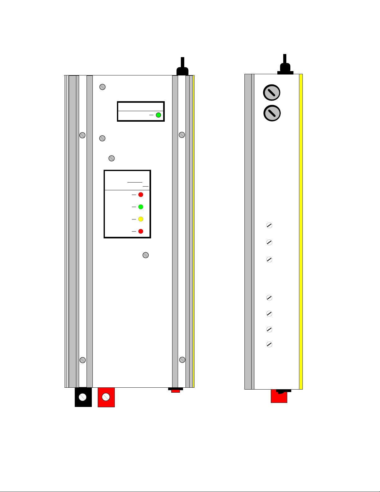
Figure #2
Figure #1
Charger Fuse
F1
POWER OUTPUT
Active When Lit
BATTERY MONITOR
When Utility AC is Down
ALL Battery Indicators Are OFF
Replace Battery
Fully Charged
F2
Main Fuse
Trickle Charge
High Charge
TOP VIEW
Inverter
ON/OFF
SIDE VIEW
12
Page 13

How to Discern When Pump Sentry is Operational in the Backup Mode
When all four LED’s of the battery monitor are OFF, and the pump sentry is plugged into an AC outlet,
the unit is in the back up mode. In this mode when there is sufficient energy in the battery to operate the
system, the uninterruptible power LED is illuminated. Once the battery is depleted the uninterruptible
power light will extinguish, indicating an absence of AC power at the Pump Sentry’s output.
How to Discern When Pump Sentry is Operational in the Standby (Line Power) Mode
When at least one of the four Battery Monitor LED’s in ON, and the pump sentry is plugged into an AC
outlet, the unit is in standby mode. In this mode, the uninterruptible power LED remains illuminated.
Fuses
Figure #2 on page 11 shows the location of two protective fuses F1 and F2.
F1, the charger fuse, provides protection against charger or battery catastrophic failure. When this fuse is
blown the pump sentry will operate on standby power only until the battery is depleted.
F2, the main fuse, provides secondary protection against severe overload. When this fuse is blown, 120
VAC to the output receptacle of the pump sentry is cut off. In this state, the Uninterruptible Power LED
will be OFF.
Audible Alarm
While operating on Battery Backup Power, when the battery is depleted to the point where it dips below
10.8V, a high pitched audible alarm is emanated from the Pump Sentry. This is a sign, to the user, that
he will imminently loose battery power. If the maintenance of battery power is crucial, the user may
substitute the spent battery for a fully charged one, by carefully following the directions in the section
“Changing the Battery” on page 10.
If the audible alarm is found to be irritable, it may be turned off by simple turning off the ON/OFF
switch of the pump sentry. IT IS IMPORTANT TO TURN THIS SWITCH BACK “ON” WHEN THE
UNIT’S OPERATION IS REINSTATED. This should take place when utility power comes back on or
after the battery has been replaced. FAILURE TO DO THIS WILL LEAVE THE USER WITHOUT
BACK UP PROTECTION.
13
Page 14

Pump Sentry 822 PS, 1622 PS
SEC America, LLC
S. Burlington, VT, 05403
Manufacturers Limited Warranty
Pump Sentry is warranted to be free from defects in material and workmanship and
to perform within applicable specifications for a period of two years after original
shipment. Obligation under this guarantee is limited to repairing or replacing any
part thereof, except fuses and pilot lights, which shall within one year returned to
us with transportation charges prepaid, and prove after our examination to be thus
defective.
The above limited warranties take the place of all other warranties, expressed of
implied and correction of such defects by replacement or repair shall constitute a
fulfillment of all obligations under the terms of the warranties. The warranties do
not cover any unit, which has been damaged either in transit or by misuse, accident
or negligence. No warranty or representation by anyone other than this Company
shall be binding on us.
Manufactured by
SEC America, LLC
78 Ethan Allen Drive,
S. Burlington, VT 05403
14
 Loading...