

Page 1
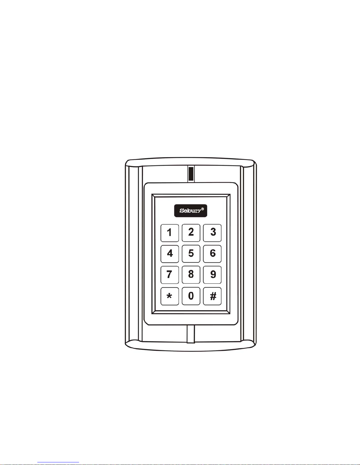
BC-2000
Digital Keypad
Page 2

2
CONTENTS Page
Introduction ……………………………………… 3
Product Specifications ………………….…….… 4
Intramural Interface Circuit ……………………… 5
Mounting & PCB Diagram ………………………. 6
Wiring Diagram …………………………………… 7
Engineer Programming Information and Notes… 9
Changing Master & User Codes…………… 9
Adding User Codes & Cards………. ……… 10
Delete User Card or Cards…………..……… 10
User Operation Mode………………………… 10
Setting Door Relay Strike…………………… 11
Setting Alarm Signal Output Time….. …… 11
Setting Door Open Detection……………… 11
Setting Security Arrangement ……………… 12
Resetting Non Volatile Memory…………………. 12
Changing User Password Code….. …………… 13
Using Password Code to release the door……… 13
Technical Specifications ….……………………… 14
Package Listing………. …………………………… 15
Page 3

3
Introduction
The BC-2000 uses the latest microprocessor
technology to operate door strikes and security
systems that require a momentary (timed) or latching
dry contact closure.
All programming is done through the keypad.
Codes and operating parameters are stored within the
microprocessor and can not be lost due to power
failure.
The BC-2000 can store 1000 prox cards and user
4 digit codes. Each 4 digit code has 10,000 possible
combinations. The unit has one relay with 5 Amp
contacts.
Page 4

4
Specifications
1. Programmable Functions
Relay latching or momentary
Relay activate independently or together
Change Codes 1 master, 1000 users & prox cards
Door open detection
2. Programmable Timers
Door relay time 00-99 seconds
Door open detection 00-99 seco nds
Alarm time 00-99 minutes
3. Wiring Connections
Electric lock
External bell
External Push Switch
Magnetic Contacts
Alarm
4. Keypad:
12 keys
5. Programming memory:
Non volatile Eeprom memory
Page 5
5
IMPORTANT INFORAMTION
There are no user serviceable parts contained within the
BC-2000 access control keypad.
If holes are to be drilled before mounting onto a wall,
check for hidden cables and/or pipes before drilling. Use
safety goggles when drilling or hammering in cable clips.
Every effort has been made to provide accurate
information, however slight variations can occur. We also
reserve the right to make changes for product
improvement at any time
NOTE
PLEASE READ THESE INSTRUCTIONS CAREFULLY
BEFORE ATTEMPTING TO INSTALL THE BC -2000
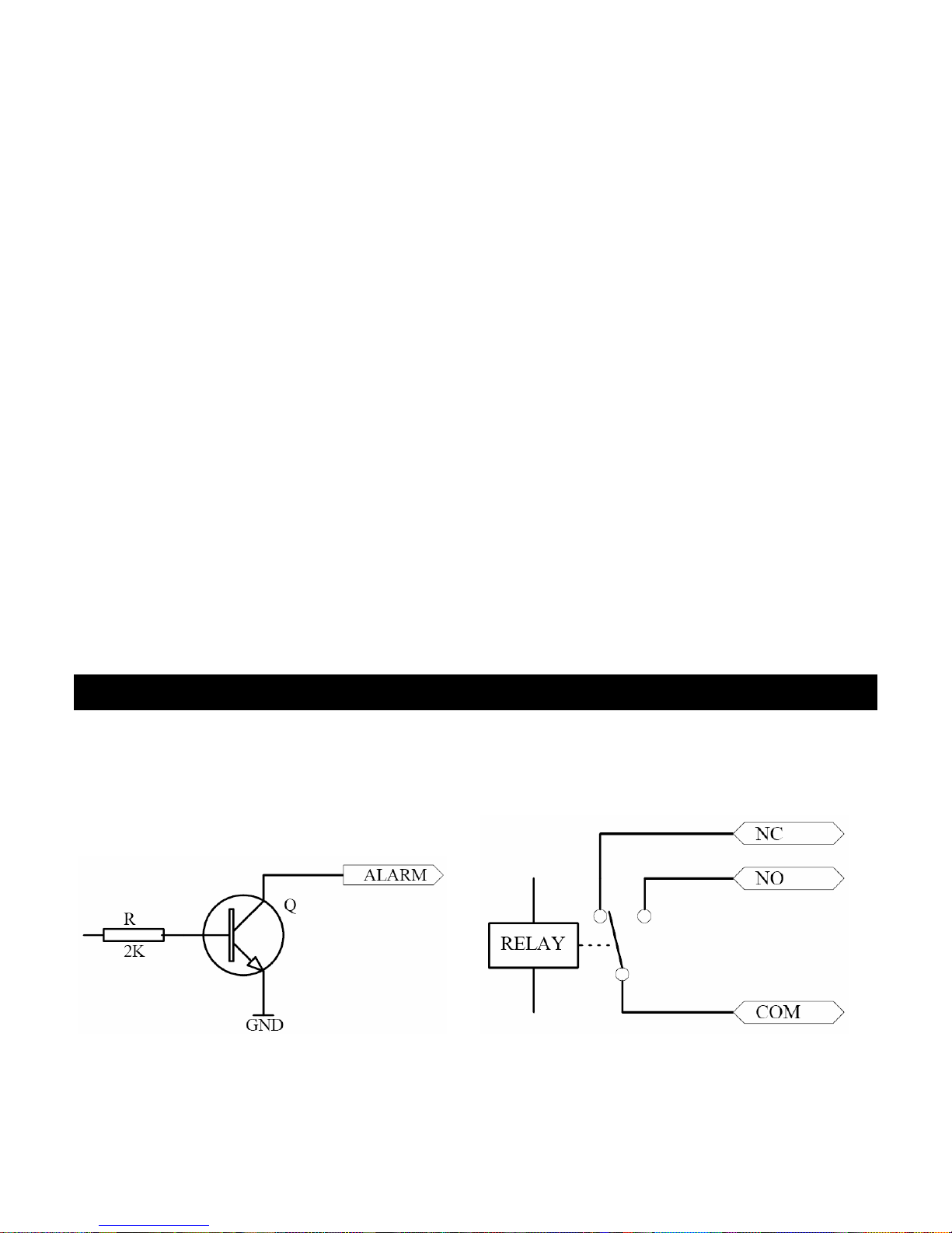
Intramural Interface Circuit
1. Alarm output interface (See Figure 1)
2. Electric lock interface (See Figure 2)
Figure 1 Figure 2
Page 6
6
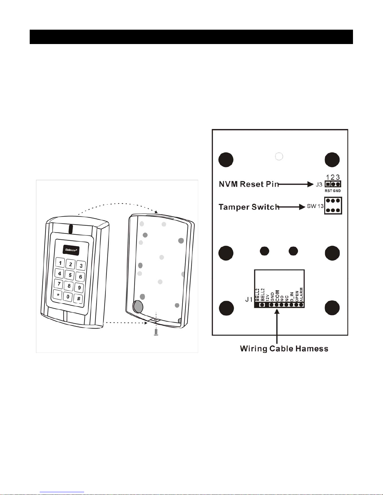
Mounting
1. Attach the rear plate to a single or double gang
electrical box or secure to the wall firmly with at least
three flat head screws.
2. When wiring has been completed, attach the front
cover to the rear plate.
Figure 3 Figure 4
The front cover can be permanently secured by using the
short screw supplied BC-2000 Printed Circuit Board
Page 7

7
Wiring
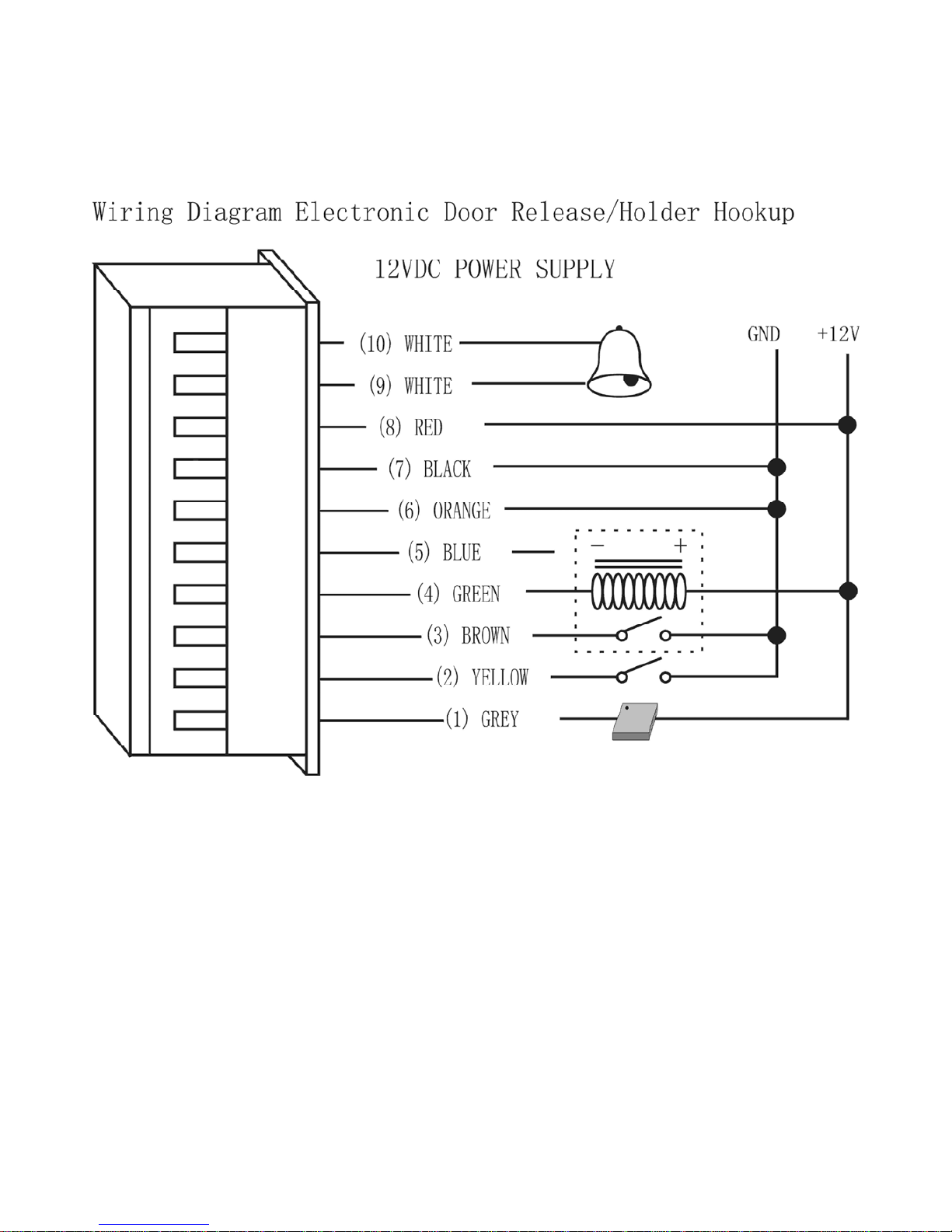
1. Unplug the cable harness and connect the necessary
cables, (See Figure 5).
2. Tape any wires that are unused.
3. Plug the cable harness , (See Figure 5)
4. Attach the front cover, (See Figure 3).
Terminal Wire Connector 1 Function
10 Bell1 White Bell Push Button
9 Bell2 White Bell Push Button
8 12V Red (+) 12Vdc Positive Regulated Power Input
7 GND Black (-) Negative Regulated Power Input
6 COM Orange Door Strike Relay Com
5 NO Blue Door Strike Relay N/O
4 NC Green Door Str ik e Relay N/C
3 D_IN Brown To Door Contact Then To Door In
2 OPEN Yellow To Door Remote Control Button Then Negative
1 ALARM Grey Alarm
DO NOT PLUG ADAPTOR OUR TRANSFORMER INTO MAINS
UNTIL ALL WIRING HAS BEEN COMPLETED AND THE
FRONT COVER SECURED.
Page 8
8
Figure 5
Page 9

9
Power Up
1. After all wiring is complete and the unit face plate is
attached to the back plate, apply 12Vdc power to the
unit. Accept LED(the yellow LED) flashing.
Engineer Programming Mode
To enter programming mode
Press: * 9999 # within 5 seconds, Ready(the green
LED) and Accept LED illuminated, Open L E D flashing.
Note:
Press: # to save changes and exit engineer
programming, when all programming has been completed
otherwise changes will not be saved.
Changing Master & User Codes
In engineer programming mode:
To change Master code
Press: 0 new master code # re-enter new m aster code #
Upon acceptance Open LED illuminates and stops
flashing. Press * after changing the master code,
otherwise unit will disregard the new code and revert back
to the factory default c o de.
Note: the master code must be 4-8 digit number.
Page 10
10
Adding User Codes & Cards
To Add User cards & codes
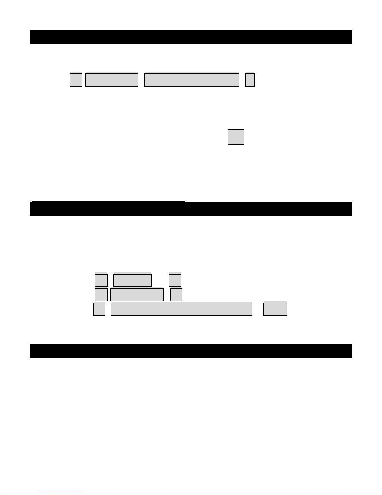
Press: 1 read card user identification #
Note: the user identification must be 3 digit number, if
adding more than 1 card, read the next card after inputting
the 3 digit code for the previous card, when you have
finished adding all cards press the # key. 1st card must
be 000 up to 999.
Then the BC-2000 control station added a user card it
was auto added a user code with 1234.
Delete User Card or Cards
There are 3 options to delete a user card or cards, in
engineering mode.
a.) Press: 2 0 0 0 0 # to delete all user cards
b.) Press: 2 Read card # to delete individual user card
c.) Press: 2 user identification number # to delete
individual user card
User Operation Mode
There are 3 differe nt o pti ons for user operation mo de,
card only, card and password, valid code. The optioned
used is common to all users.
Page 11
11
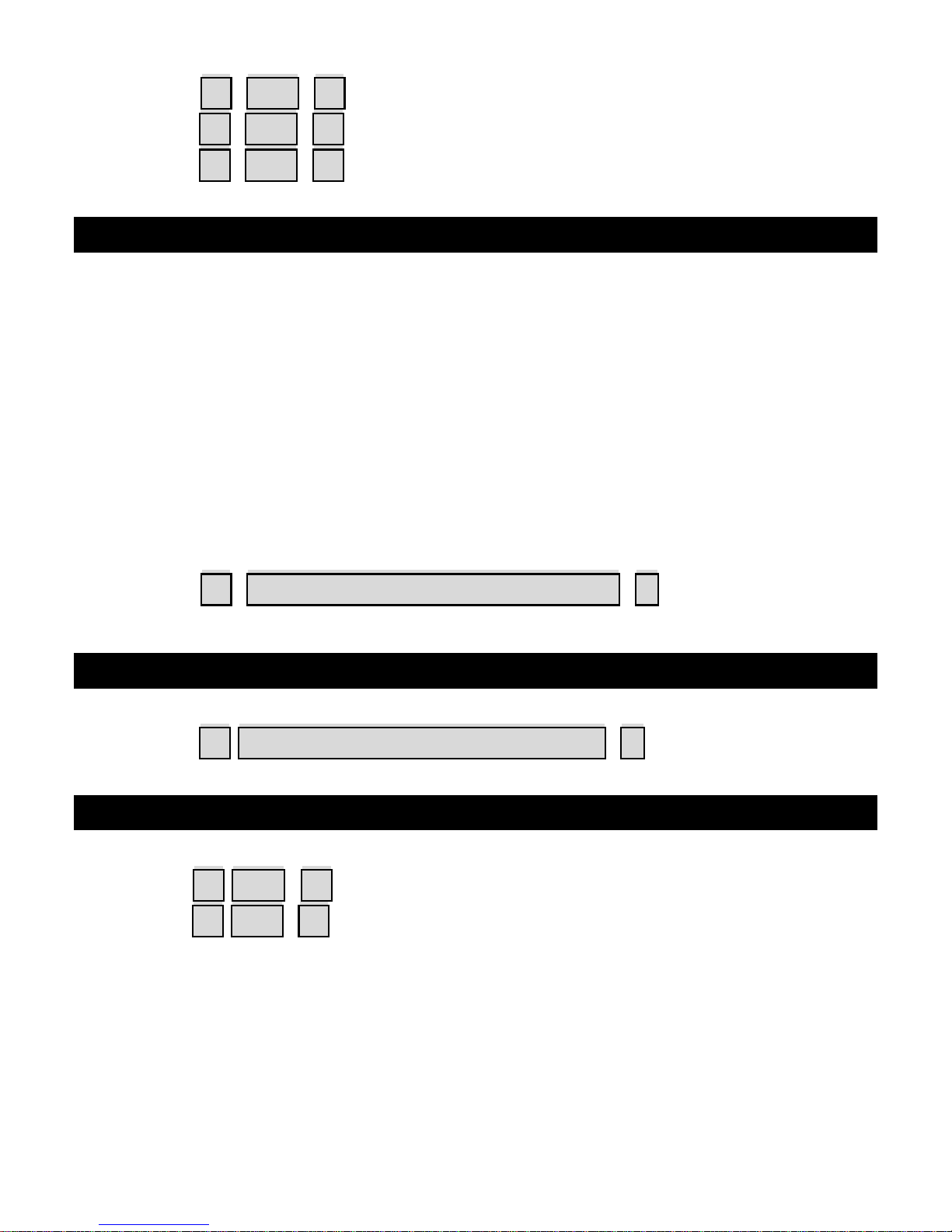
Press: 3 0 0 # valid card only
Press: 3 0 1 # valid card and password
Press: 3 0 2 # valid card or password
Setting Door Relay Strike Time
The door relay output can be operated as either normally
opened or normally closed, a maximum current of 10
ampere can pass through the relay if used as normally
opened or 5 ampere if normally closed. The door relay
time can be set from 0 seconds to a maximum of 99
seconds. The factory default setting is 6 seconds and can
be changed through the keypad.
Press: 4 new time from 00-99 seconds #
Setting Alarm Signal Output Time
Press: 5 new time from 00-99 minutes #
Setting Door Open Detection
Press: 6 0 0 # to disable this function (factory setting)
Press: 6 0 1 # to enable this function.
In order for this feature to work, door contacts must be
connected. There are 2 programming functions that work
together in this mode.
Page 12
12
a.) If door not closed after opening, keypad buzzer
sounds.
b.) If door forced open, keypad buzzer sounds and
sends alarm signal.
Setting Security Arrangement
There are two levels of keypad security available for the BC-
2000.
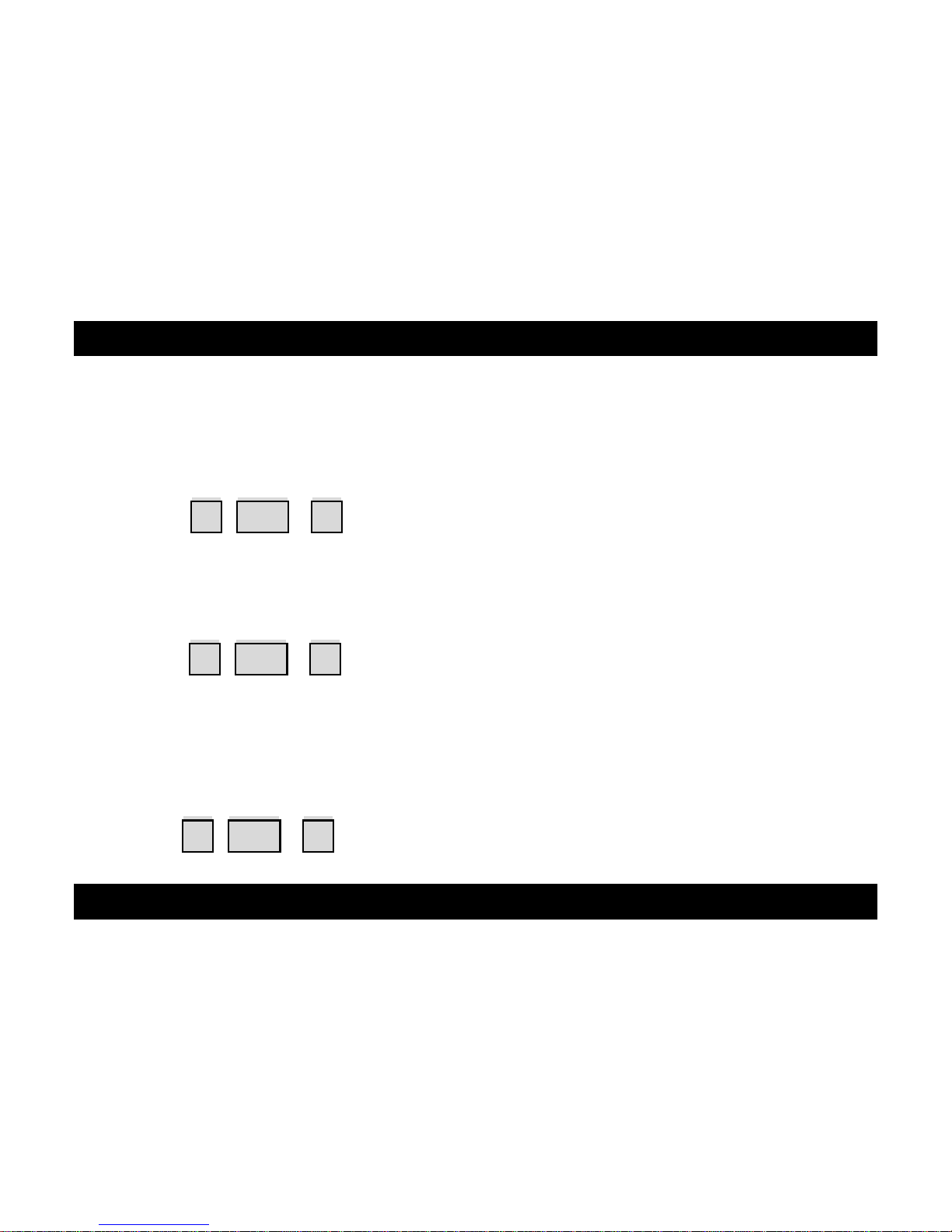
Press: 7 0 1 # to read 10 invalid cards or valid cards,
then enter 4 wrong passwords in succession, the keypad is
locked for 10 minutes.
Press: 7 0 2 # to read 10 invalid cards or valid cards,
then enter 4 wrong passwords in succession, the keypad
activates and alarm signal.
To disable this feature:
Press: 7 0 0 # factory default setting.
Resetting To Factory Default Setting
To revert all settings to the factory default values then the
Non Volatile Memory (Eeprom) must be reset.
Page 13

13
Reset Non Volatile Memory by switching of the power and
placing the jumper connector onto the pins 1 & 2 as per
figure 2. After switching power on remove jumper, the BC2000 will give a beep and is now reset to factory default
values.
Changing User Password Code
The factory default setting for each user password code
1234, this can be modified so that each user has a unique
individual 4 digit code.
Press: * read user card user passoword # new passwor d
# re-enter new password #
Using Password Code to release the door
Press: user passoword #
Page 14

14
Technical Specification
DC Supply Voltage: Low voltage input
12 ±10% Vdc unregulated
Current Consumption: 100mA @ quiescent maximum
Door Relay: 5Amp 12Vdc
Alarm output load: 150mA pull current
Tamper Protection: Negative loop, normally closed
Codes : 1 Master, 1000 cards
and 1000 codes .
Keypad: 12 keys, 3 LED status indicators
Card Types: EM or EM compatible
Induction Distance: 5-8cm
Wiring Connections: Electric lock
Remote door control
Door open detection
External door bell
External Alarm
Memory: Non volatile eeprom memory
Operating Temperature: 0°C to 60°C (32°F to 140°F)
Keypad Housing: Metal
Dimensions: 128mm x 82mm x 28mm
Weight: 500g
Page 15

15
Package Listing
Name Model no. Quantity Remark
Digital Keypad BC-2000 1
User Manual BC-2000 1
Flat Head
Screws
Φ3mm×6mm
1
Used for front
case and back
case
Pastern Stopper
Φ6mm×27 mm
4 Used for fixing
Self Tapping
Screws
Φ3.5mm×27 mm
4 Used for fixi ng
 Loading...