

Sears, Roebuck and Co. pro-form 10.8x User Manual
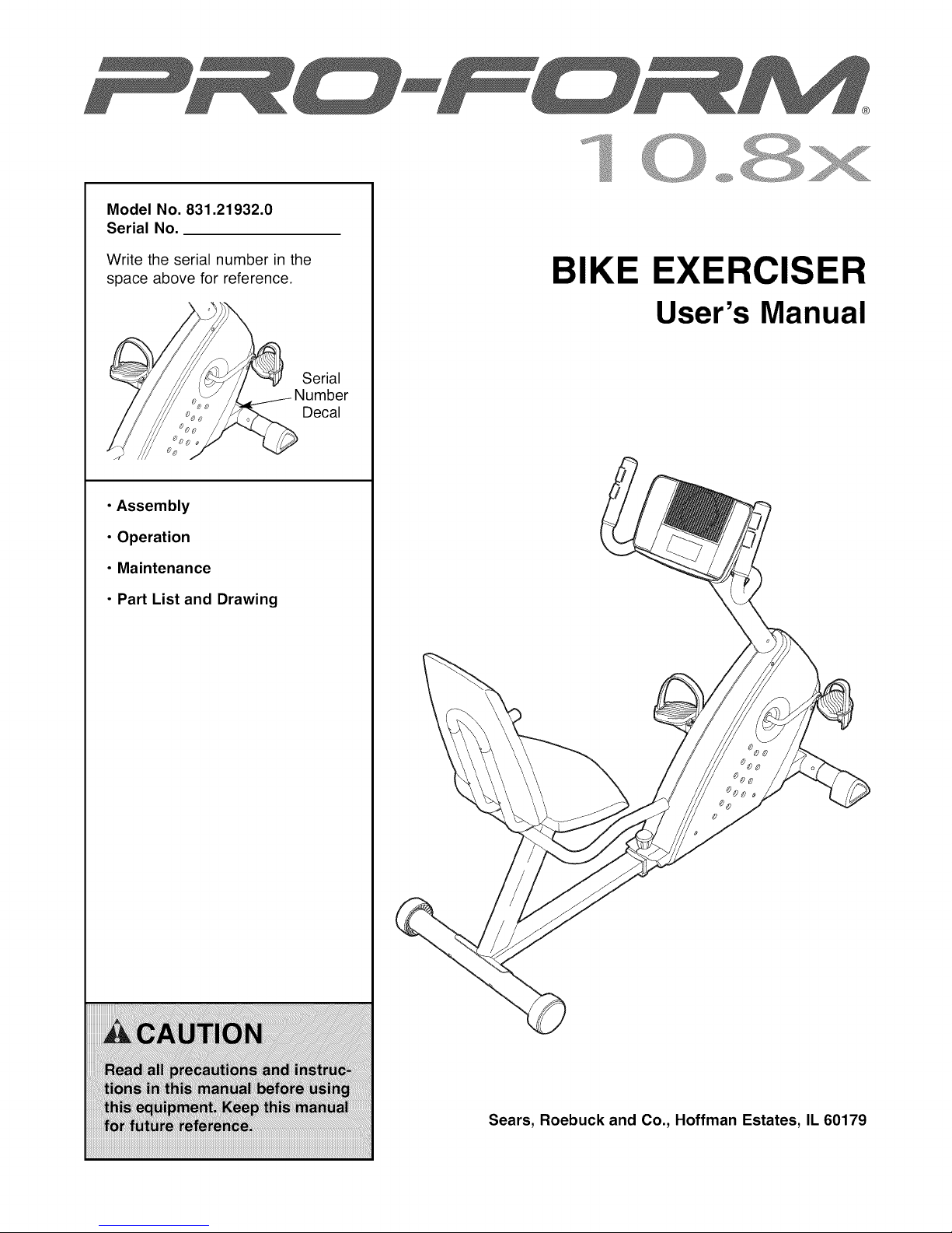
Model No. 831.21932.0
Serial No.
Write the serial number in the
space above for reference.
• Assembly
• Operation
• Maintenance
• Part List and Drawing
BIKE EXERCISER
User's Manual
Serial
Decal
Sears, Roebuck and Co., Hoffman Estates, IL 60179
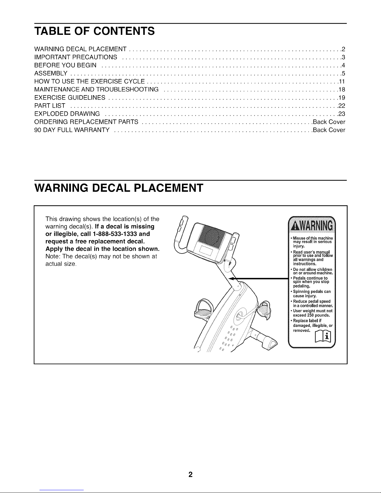
TABLE OF CONTENTS
WARNING DECAL PLACEMENT .............................................................. 2
IMPORTANT PRECAUTIONS ................................................................ 3
BEFORE YOU BEGIN ...................................................................... 4
ASSEMBLY ............................................................................... 5
HOW TO USE THE EXERCISE CYCLE ........................................................ 11
MAINTENANCE AND TROUBLESHOOTING ................................................... 18
EXERCISE GUIDELINES ................................................................... 19
PART LIST .............................................................................. 22
EXPLODED DRAWING .................................................................... 23
ORDERING REPLACEMENT PARTS .................................................. Back Cover
90 DAY FULL WARRANTY .......................................................... Back Cover
WARNING DECAL PLACEMENT
This drawing shows the location(s) of the
warning decal(s). If a decal is missing
or illegible, call 1-888-533-1333 and
request a free replacement decal.
Apply the decal in the location shown.
Note: The decal(s) may not be shown at
actual size.
•Misuse ofthis machine
may result inserious
injury.
• Read user's manual
prior to use and follow
all warnings and
instructions.
• Do not allow children
on or around machine.
• Pedals continue to
spin when you stop
pedaling,
•Spinning pedals can
cause injury.
• Reduce pedal speed
ina controfledmanner.
• User weight must not
exceed 250 pounds.
• Replace label if
damaged, illegible, or
removed. [_
2
IMPORTANT PRECAUTIONS
AWARNING: To reduce the risk of serious injury, read all important precautions and
instructions in this manual and all warnings on your exercise cycle before using your exercise
cycle. Sears assumes no responsibility for personal injury or property damage sustained by or
through the use of this product.
1. Before beginning any exercise program, 8.
consult your physician. This is especially
important for persons over the age of 35 or
persons with pre-existing health problems.
.
It is the responsibility of the owner to ensure
that all users of the exercise cycle are ade-
quately informed of all precautions.
.
Your exercise cycle is intended for home use
only. Do not use your exercise cycle in a
commercial, rental, or institutional setting.
.
Keep your exercise cycle indoors, away from
moisture and dust. Place your exercise cycle
on a level surface, with a mat beneath it to
protect the floor or carpet. Make sure that
there is at least 2 ft. (0.6 m) of clearance
around your exercise cycle.
.
Inspect and properly tighten all parts regu-
larly. Replace any worn parts immediately.
.
Keep children under age 12 and pets away
from your exercise cycle at all times.
The pulse sensor is not a medical device.
Various factors, including the user's move-
ment, may affect the accuracy of heart rate
readings. The pulse sensor is intended only
as an exercise aid in determining heart rate
trends in general.
g.
Wear appropriate exercise clothes while
exercising; do not wear loose clothes that
could become caught on your exercise
cycle. Always wear athletic shoes for foot
protection while exercising.
10. Keep your back straight while using your
exercise cycle; do not arch your back.
11. When you stop exercising, allow the pedals
to slowly come to a stop.
12. If you feel pain or dizziness while exercising,
stop immediately and cool down.
13. Use your exercise cycle only as described in
this manual.
7. Your exercise cycle should not be used by
persons weighing more than 250 Ibs. (113
kg).
3
BEFORE YOU BEGIN
Thank you for selecting the new PROFORM ®10.8X
exercise cycle. Cycling is one of the most effective
exercises for increasing cardiovascular fitness, build-
ing endurance, and toning the body. The 10.8X exer-
cise cycle offers a selection of features designed to let
you enjoy this healthful exercise in the convenience
and privacy of your home.
For your benefit, read this manual carefully before
you use the exercise cycle. If you have questions
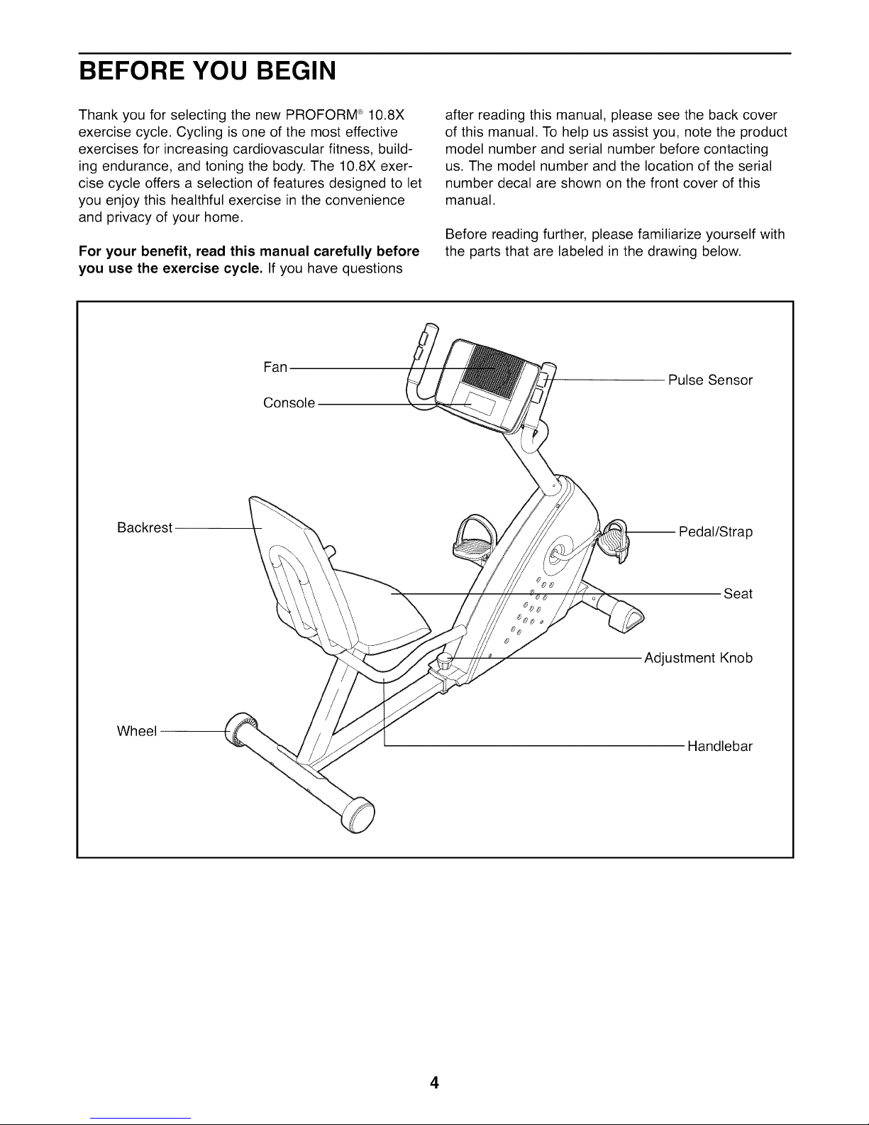
Fan !
Console
Backrest
\
after reading this manual, please see the back cover
of this manual. To help us assist you, note the product
model number and serial number before contacting
us. The model number and the location of the serial
number decal are shown on the front cover of this
manual.
Before reading further, please familiarize yourself with
the parts that are labeled in the drawing below.
Pulse Sensor
-- Pedal/Strap
Wheel
Seat
Adjustment Knob
Handlebar
4
ASSEMBLY
Assembly requires two persons. Place all parts of the exercise cycle in a cleared area and remove the pack-
ing materials. Do not dispose of the packing materials until assembly is completed.
In addition to the included tool(s), assembly requires a Phillips screwdriver _A_====_ and an
adjustable wrench _.
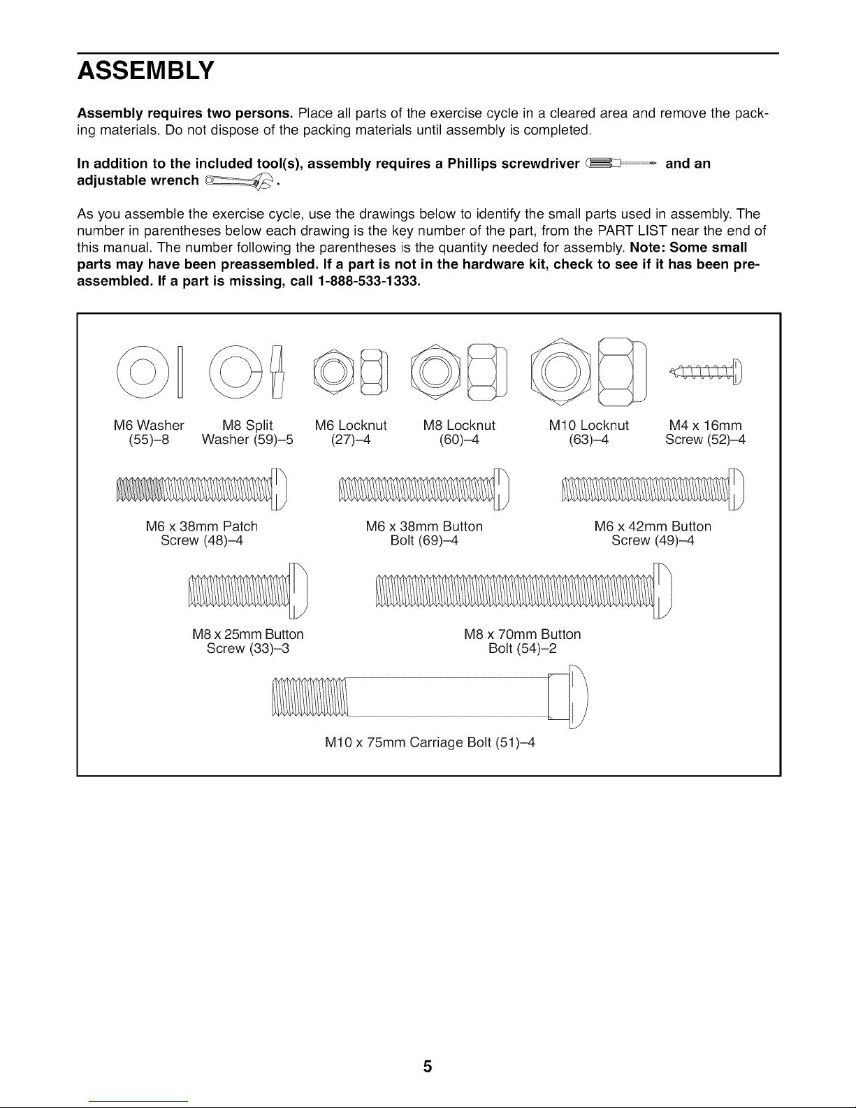
As you assemble the exercise cycle, use the drawings below to identify the small parts used in assembly. The
number in parentheses below each drawing is the key number of the part, from the PART LIST near the end of
this manual. The number following the parentheses is the quantity needed for assembly. Note: Some small
parts may have been preassembled. If a part is not in the hardware kit, check to see if it has been pre-
assembled. If a part is missing, call 1-888-533-1333.
M6 Washer
(55)-8
M6 x 38mm Patch
Screw (48)-4
M8 Split
Washer (59)-5
M8 x 25mm Button
Screw (33)-3
M6 Locknut
(27)-4
M6 x 38mm Button
M10 x 75mm Carriage Bolt (51)-4
M8 Locknut
(60)-4
Bolt (69)-4
M8 x 70mm Button
Bolt (54)-2
M10 Locknut
(63)-4
M6 x 42mm Button
Screw (49)-4
M4 x 16mm
Screw (52)-4
5
.
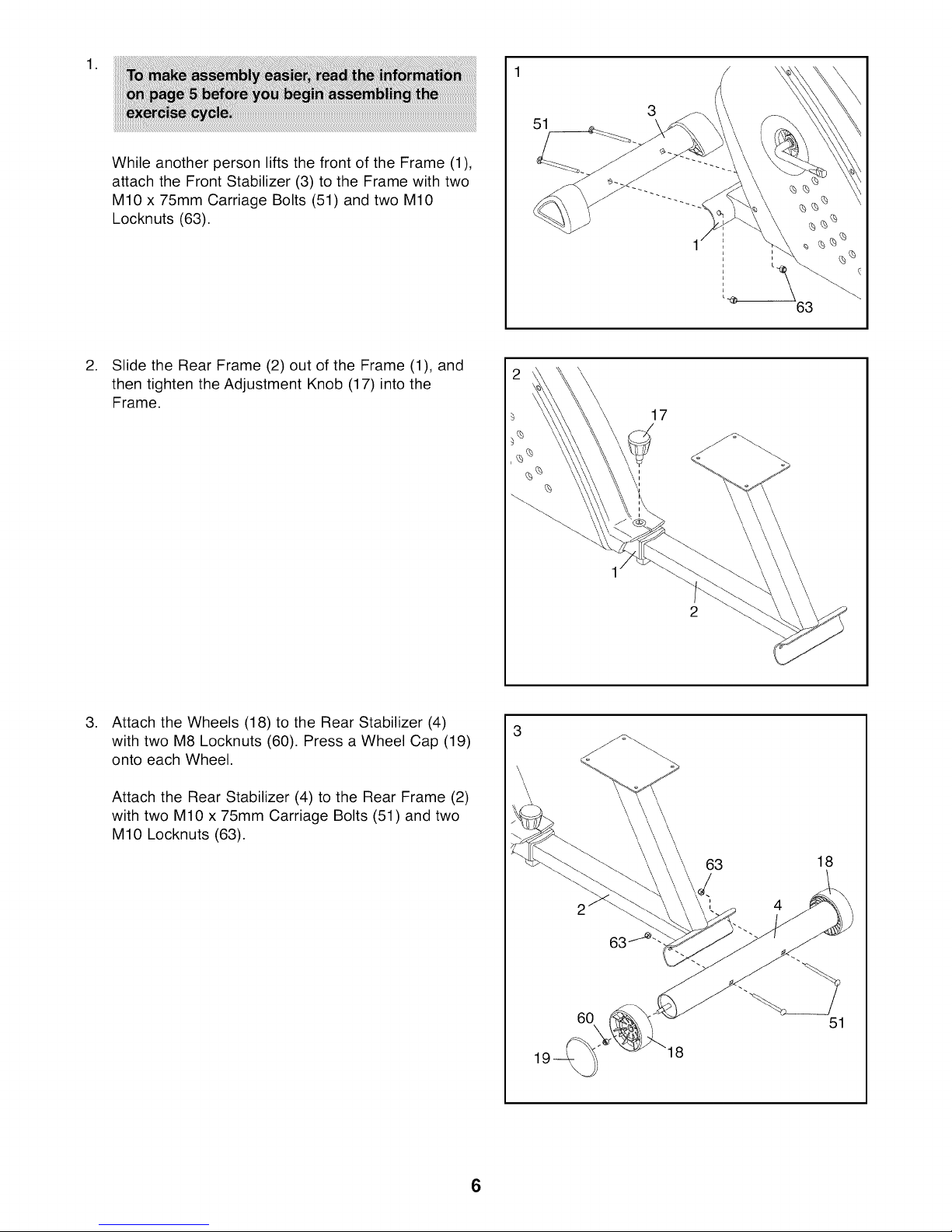
While another person lifts the front of the Frame (1),
attach the Front Stabilizer (3) to the Frame with two
M10 x 75mm Carriage Bolts (51) and two M10
Locknuts (63).
.
Slide the Rear Frame (2) out of the Frame (1), and
then tighten the Adjustment Knob (17) into the
Frame.
51
3
63
17
.
Attach the Wheels (18) to the Rear Stabilizer (4)
with two M8 Locknuts (60). Press a Wheel Cap (19)
onto each Wheel.
Attach the Rear Stabilizer (4) to the Rear Frame (2)
with two M10 x 75mm Carriage Bolts (51) and two
M10 Locknuts (63).
3
18
19
60
18
51
6
,
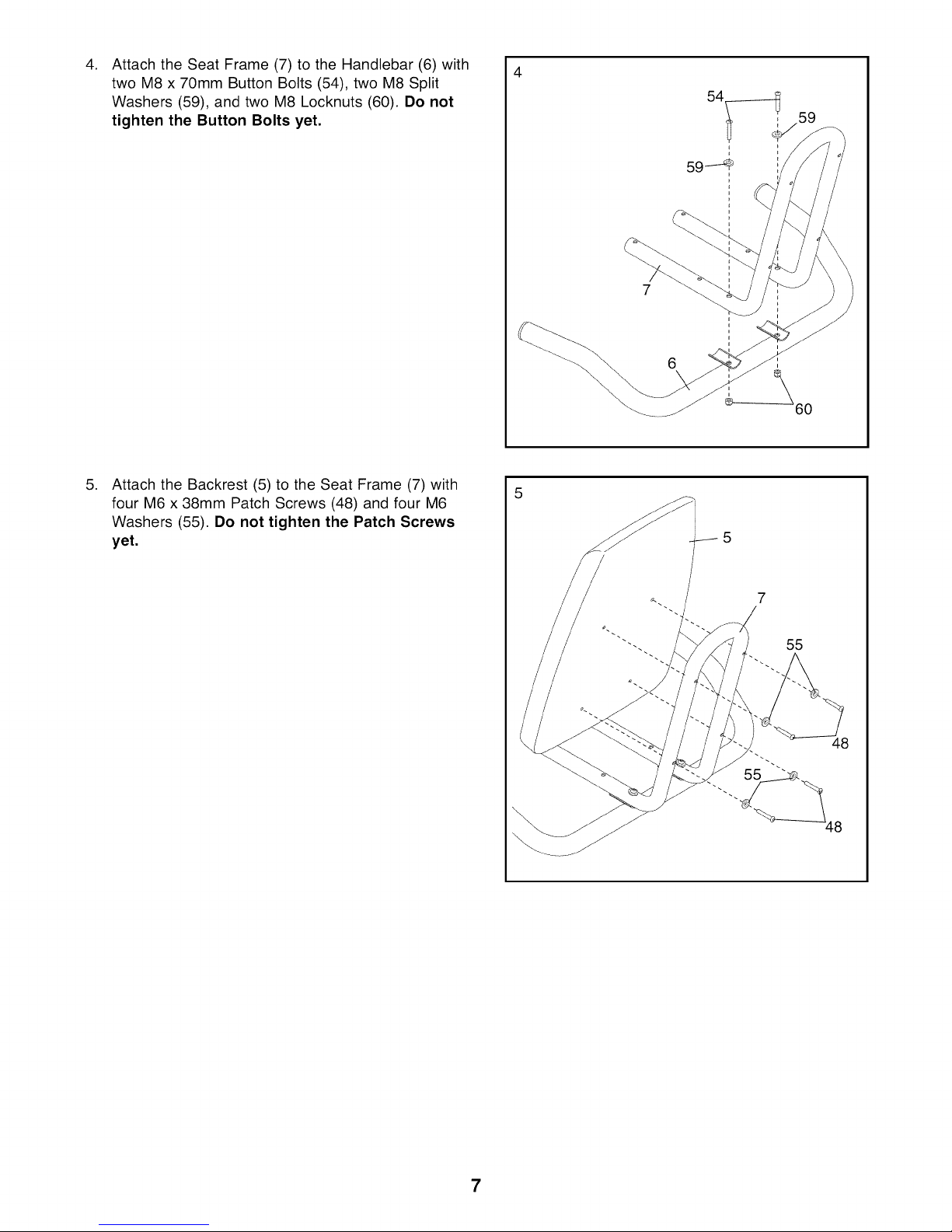
Attach the Seat Frame (7) to the Handlebar (6) with
two M8 x 70mm Button Bolts (54), two M8 Split
Washers (59), and two M8 Locknuts (60). Do not
tighten the Button Bolts yet.
,
Attach the Backrest (5) to the Seat Frame (7) with
four M6 x 38mm Patch Screws (48) and four M6
Washers (55). Do not tighten the Patch Screws
yet.
6
7
55
7
.
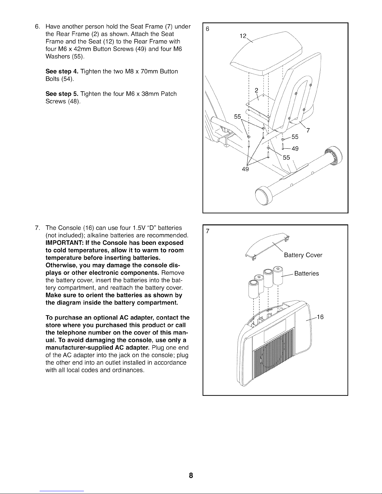
Have another person hold the Seat Frame (7) under
the Rear Frame (2) as shown. Attach the Seat
Frame and the Seat (12) to the Rear Frame with
four M6 x 42mm Button Screws (49) and four M6
Washers (55).
See step 4. Tighten the two M8 x 70mm Button
Bolts (54).
See step 5. Tighten the four M6 x 38mm Patch
Screws (48).
6
12 /Jf_
49
.
The Console (16) can use four 1.5V "D" batteries
(not included); alkaline batteries are recommended.
IMPORTANT: If the Console has been exposed
to cold temperatures, allow it to warm to room
temperature before inserting batteries.
Otherwise, you may damage the console dis-
plays or other electronic components. Remove
the battery cover, insert the batteries into the bat-
tery compartment, and reattach the battery cover.
Make sure to orient the batteries as shown by
the diagram inside the battery compartment.
To purchase an optional AC adapter, contact the
store where you purchased this product or call
the telephone number on the cover of this man-
ual. To avoid damaging the console, use only a
manufacturer-supplied AC adapter. Plug one end
of the AC adapter into the jack on the console; plug
the other end into an outlet installed in accordance
with all local codes and ordinances.
8
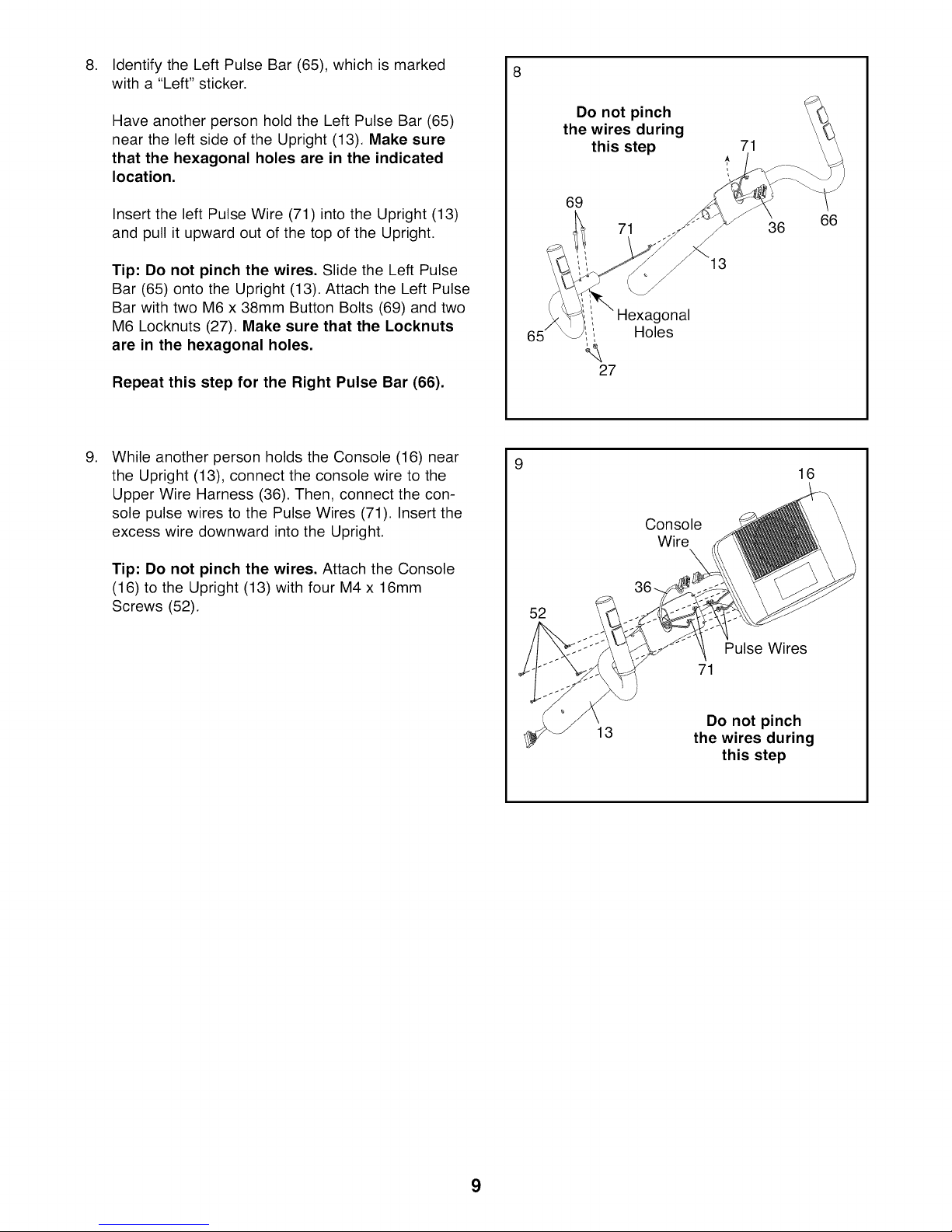
Identify the Left Pulse Bar (65), which is marked
8. 8
with a "Left" sticker.
Have another person hold the Left Pulse Bar (65)
near the left side of the Upright (13). Make sure
that the hexagonal holes are in the indicated
location.
Insert the left Pulse Wire (71) into the Upright (13)
and pull it upward out of the top of the Upright.
Tip: Do not pinch the wires. Slide the Left Pulse
Bar (65) onto the Upright (13). Attach the Left Pulse
Bar with two M6 x 38mm Button Bolts (69) and two
M6 Locknuts (27). Make sure that the Locknuts
are in the hexagonal holes.
Repeat this step for the Right Pulse Bar (66).
.
While another person holds the Console (16) near
the Upright (13), connect the console wire to the
Upper Wire Harness (36). Then, connect the con-
sole pulse wires to the Pulse Wires (71). Insert the
excess wire downward into the Upright.
Do not pinch
the wires during
this step
69
71
onal
i Holes
27
Console
Wire
13
71
36
66
16
Tip: Do not pinch the wires. Attach the Console
(16) to the Upright (13) with four M4 x 16mm
Screws (52).
52
13
Pulse Wires
71
Do not pinch
the wires during
this step
9
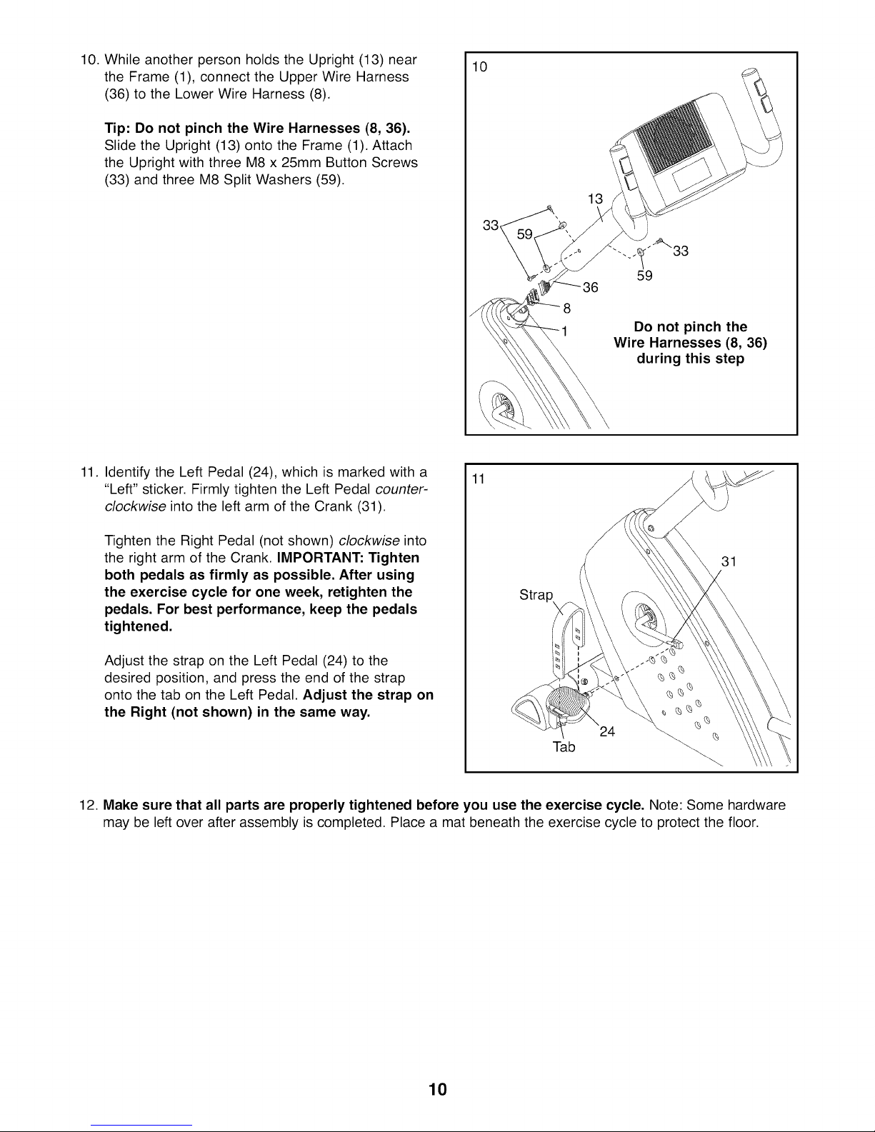
10. While another person holds the Upright (13) near
the Frame (1), connect the Upper Wire Harness
(36) to the Lower Wire Harness (8).
Tip: Do not pinch the Wire Harnesses (8, 36).
Slide the Upright (13) onto the Frame (1). Attach
the Upright with three M8 x 25mm Button Screws
(33) and three M8 Split Washers (59).
10
13
Do not pinch the
Wire Harnesses (8, 36)
during this step
11. Identify the Left Pedal (24), which is marked with a
"Left" sticker. Firmly tighten the Left Pedal counter-
clockwise into the left arm of the Crank (31).
Tighten the Right Pedal (not shown) clockwise into
the right arm of the Crank. IMPORTANT: Tighten
both pedals as firmly as possible. After using
the exercise cycle for one week, retighten the
pedals. For best performance, keep the pedals
tightened.
Adjust the strap on the Left Pedal (24) to the
desired position, and press the end of the strap
onto the tab on the Left Pedal. Adjust the strap on
the Right (not shown) in the same way.
12. Make sure that all parts are properly tightened before you use the exercise cycle. Note: Some hardware
may be left over after assembly is completed. Place a mat beneath the exercise cycle to protect the floor.
11
31
Stra
24
Tab
10
HOW TO USE THE EXERCISE CYCLE
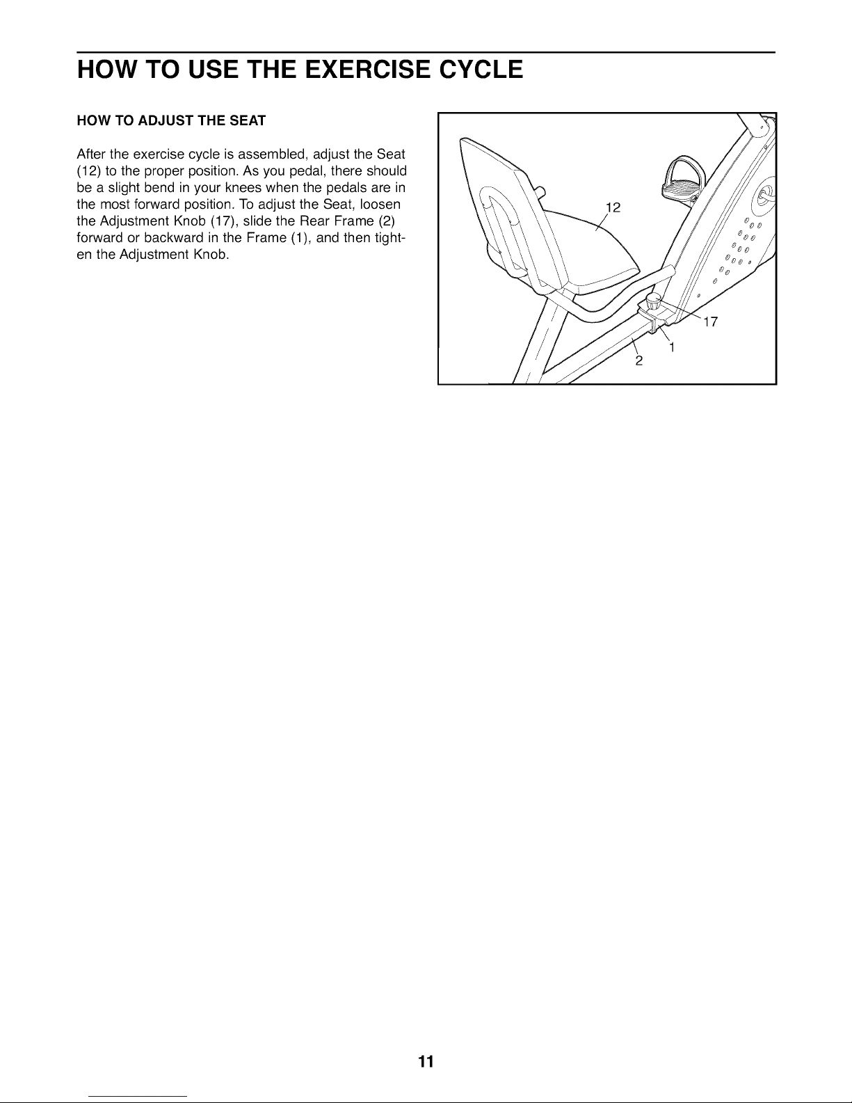
HOW TO ADJUST THE SEAT
After the exercise cycle is assembled, adjust the Seat
(12) to the proper position. As you pedal, there should
be a slight bend in your knees when the pedals are in
the most forward position. To adjust the Seat, loosen
the Adjustment Knob (17), slide the Rear Frame (2)
forward or backward in the Frame (1), and then tight-
en the Adjustment Knob.
12
1
2
11
CONSOLE DIAGRAM
WORKOUTS
mmm[]mm
m []
m []
[] []
[]
[]__
WORKOUTS
RESISTANCE
[]
Resislance
S
I
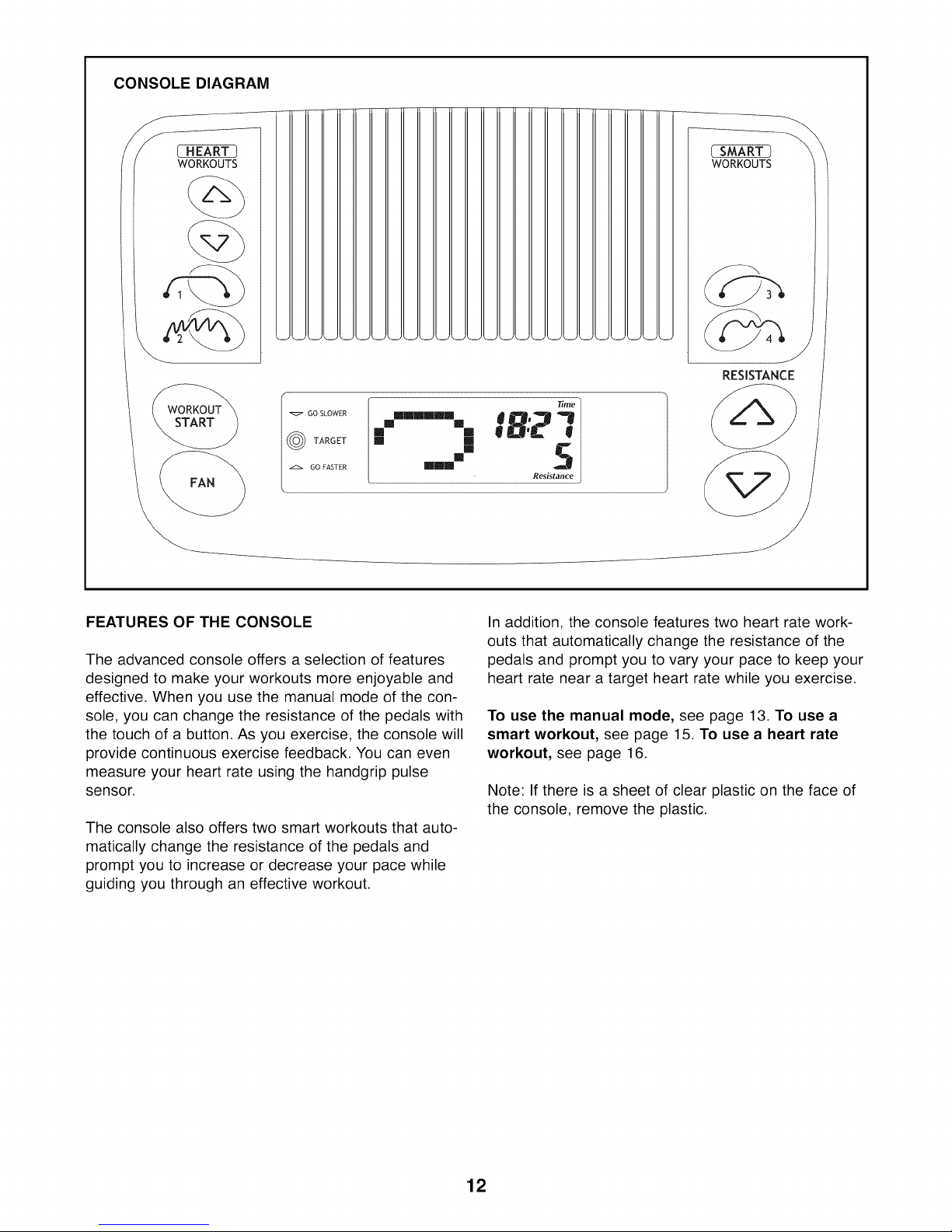
FEATURES OF THE CONSOLE
The advanced console offers a selection of features
designed to make your workouts more enjoyable and
effective. When you use the manual mode of the con-
sole, you can change the resistance of the pedals with
the touch of a button. As you exercise, the console will
provide continuous exercise feedback. You can even
measure your heart rate using the handgrip pulse
sensor.
The console also offers two smart workouts that auto-
matically change the resistance of the pedals and
prompt you to increase or decrease your pace while
guiding you through an effective workout.
In addition, the console features two heart rate work-
outs that automatically change the resistance of the
pedals and prompt you to vary your pace to keep your
heart rate near a target heart rate while you exercise.
To use the manual mode, see page 13. To use a
smart workout, see page 15. To use a heart rate
workout, see page 16.
Note: If there is a sheet of clear plastic on the face of
the console, remove the plastic.
12
HOW TO USE THE MANUAL MODE
1. Press any button on the console or begin
pedaling to turn on the console.
A few seconds after the console is turned on, the
displays will light. A tone will then sound and the
console will be ready for use.
2. Select the manual mode.
If you have
selected a work-
out, reselect the
manual mode
by pressing a
Smart Workouts
button once or
twice until a track appears in the left display and
the time is reset to zero.
3. Begin pedaling and change the resistance of
the pedals as desired.
As you pedal, change
the resistance of the
pedals by pressing the
Resistance increase or
decrease buttons.
Note: After you press
the Resistance, it will
take a moment for the pedals to reach the select-
ed resistance level.
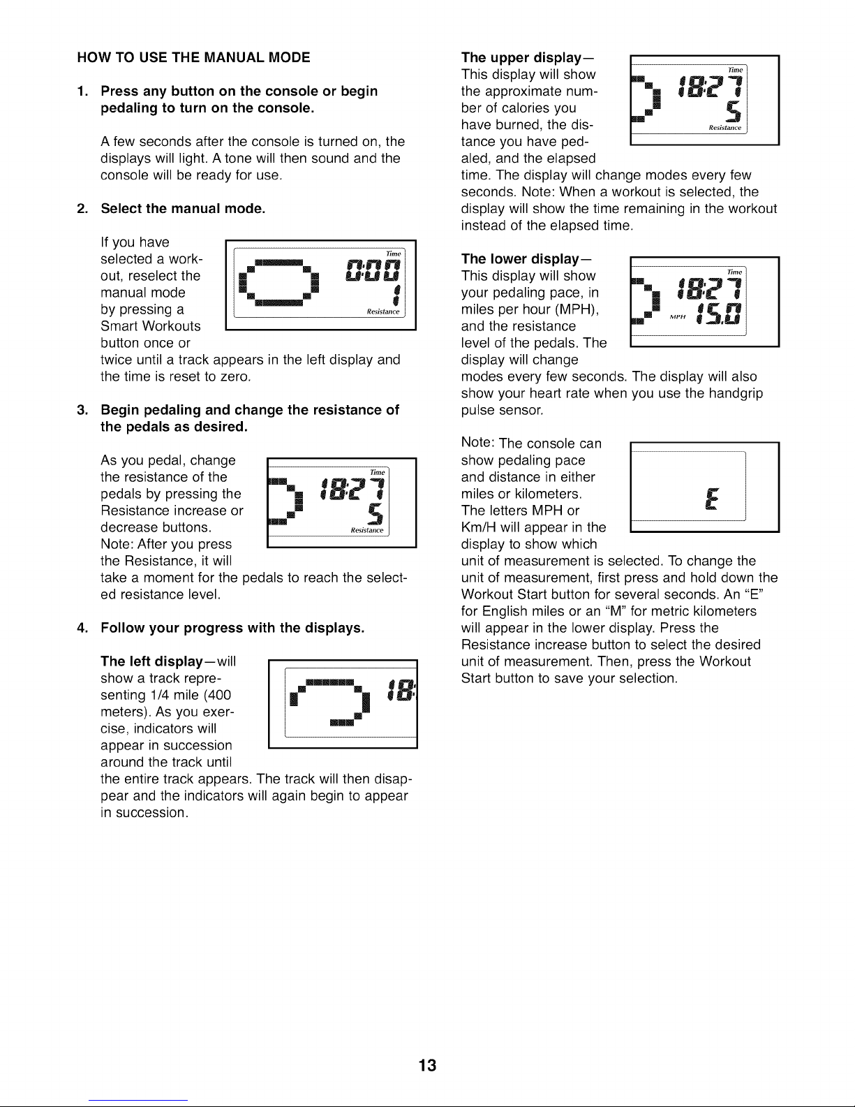
4. Follow your progress with the displays.
The left display--will
show a track repre-
senting 1/4 mile (400
meters). As you exer-
cise, indicators will
appear in succession
around the track until
the entire track appears. The track will then disap-
pear and the indicators will again begin to appear
in succession.
•.--- n.n"°'nl
m []
[] [] U'UU)
[] []
Resistan
[] []
m |
" fS:I
___
[]
This display will show [] _"°
the approximate hum- _,,, _ B"_ "'_
ber of calories you
The upper display-- t/__|
have burned, the dis- Ro,_t"_.....
tance you have ped-
aled, and the elapsed
time. The display will change modes every few
seconds. Note: When a workout is selected, the
display will show the time remaining in the workout
instead of the elapsed time.
The lower display--
This display will show
your pedaling pace, in
miles per hour (MPH),
and the resistance
level of the pedals. The
display will change
modes every few seconds. The display will also
show your heart rate when you use the handgrip
pulse sensor.
Note: The console can
show pedaling pace
and distance in either
miles or kilometers.
The letters MPH or
Km/H will appear in the
display to show which
unit of measurement is selected. To change the
unit of measurement, first press and hold down the
Workout Start button for several seconds. An "E"
for English miles or an "M" for metric kilometers
will appear in the lower display. Press the
Resistance increase button to select the desired
unit of measurement. Then, press the Workout
Start button to save your selection.
I=
13

5. Measure your heart rate if desired.
If there are sheets of
clear plastic on the
metal contacts on
the handgrip pulse
sensor, remove the
plastic. To measure
your heart rate, hold
the handgrip pulse
sensor, with your
palms resting against
the metal contacts. Avoid moving your hands or
gripping the contacts tightly.
increase or decrease your pedaling speed. Press
the Fan button repeatedly to select a fan speed or
to turn off the fan. Note: If the pedals do not move
for about thirty seconds, the fan will turn off auto-
matically.
Slide the thumb tab on
the right side of the fan
to pivot the fan to the
desired angle.
When your pulse is detected, your heart rate will
be shown in the lower display. For the most accu-
rate heart rate reading, hold the contacts for at
least 15 seconds. Note: If you continue to hold the
handgrip pulse sensor, the lower display will show
your heart rate for up to 30 seconds. The display
will then show your heart rate along with the other
modes.
If your heart rate is not shown, make sure that
your hands are positioned as described. Be care-
ful not to move your hands excessively or to
squeeze the metal contacts tightly.
6. Turn on the fan if desired.
The fan has high, low, and auto speed settings;
while the auto mode is selected, the speed of the
fan will automatically increase or decrease as you
.
When you are finished exercising, the console
will turn off automatically.
If the pedals do not move for several seconds, a
tone will sound, the console will pause, and the
time will begin to flash in the upper display.
If the pedals do not move for a few minutes, the
console will turn off and the displays will be reset.
14
HOW TO USE A SMART WORKOUT
1. Press any button on the console or begin
pedaling to turn on the console.
A few seconds after the console is turned on, the
displays will light. A tone will then sound and the
console will be ready for use.
2. Select a smart workout.
To select a smart workout, press one of the Smart
Workouts buttons on the right of the console.
When you
select a smart
Profile
workout, a pro-
file of the resis-
tance settings of
the workout will
scroll across the
Ilmmmmll
mmmlmllmlmm
_U'U U
[] S
Resistance Resistance
left display. In
addition, the
maximum resistance setting of the workout will
flash in the lower display for a moment and the
workout time will appear in the upper display.
3. Press the Workout Start button or begin
pedaling to start the workout.
Each workout is divided into 20 one-minute seg-
ments. One resistance setting and one pace set-
ting are programmed for each segment. Note: The
same resistance setting and/or pace setting may
be programmed for two or more consecutive seg-
ments.
During the workout, the workout profile will show
your progress (see the drawing above). The flash-
ing segment of the profile represents the current
segment of the workout. The height of the flashing
segment indicates the resistance level for the cur-
rent segment. At the end of each segment of the
workout, a series of tones will sound and the next
segment of the profile will begin to flash. If a differ-
ent resistance level is programmed for the next
segment, the resistance level will appear in the
display for a few seconds to alert you. The resis-
tance of the pedals will then change.
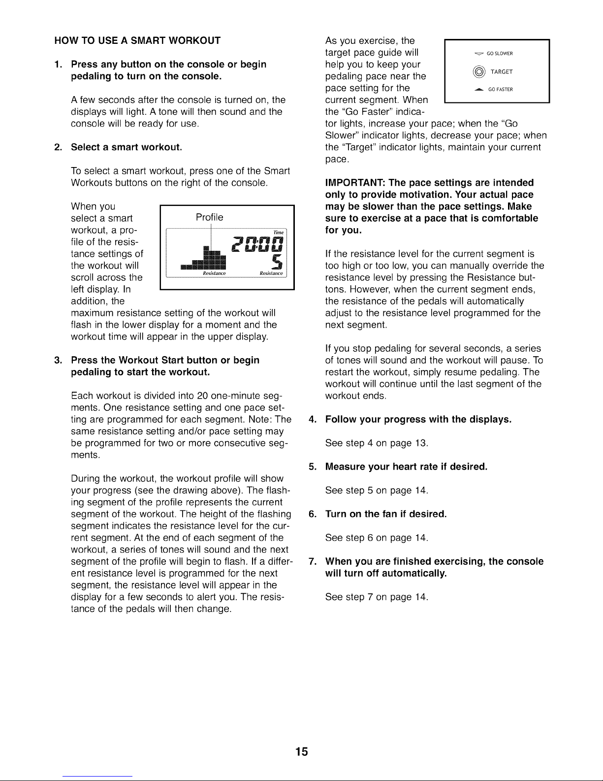
As you exercise, the
target pace guide will ._ GOSLOWER
help you to keep your
pedaling pace near the (_) TARGET
pace setting for the A GOFAS+E_
current segment. When
the "Go Faster" indica-
tor lights, increase your pace; when the "Go
Slower" indicator lights, decrease your pace; when
the "Target" indicator lights, maintain your current
pace.
IMPORTANT: The pace settings are intended
only to provide motivation. Your actual pace
may be slower than the pace settings. Make
sure to exercise at a pace that is comfortable
for you.
If the resistance level for the current segment is
too high or too low, you can manually override the
resistance level by pressing the Resistance but-
tons. However, when the current segment ends,
the resistance of the pedals will automatically
adjust to the resistance level programmed for the
next segment.
If you stop pedaling for several seconds, a series
of tones will sound and the workout will pause. To
restart the workout, simply resume pedaling. The
workout will continue until the last segment of the
workout ends.
4. Follow your progress with the displays.
See step 4 on page 13.
5. Measure your heart rate if desired.
See step 5 on page 14.
6. Turn on the fan if desired.
See step 6 on page 14.
.
When you are finished exercising, the console
will turn off automatically.
See step 7 on page 14.
15
 Loading...