

Sears, Roebuck and Co. 103.22160 Operating Instructions And Parts List Manual
r
-_/
"\
OPERATING INSTRUCTIONS
AND PARTS- LIST FOR
..
BENCH
8 INCH
SAW
r
I
i
I
Model Number 103.22160
The model number of your Bench Sawwillbe found on
a plate on the rear of the Base. Alwaysmention this
model number when communicating with us regarding
your Bench Sawor when ordering parts.
-=tnstf'uctions
rqr
OrderIng Parts
All parts listed herein must be ordered through a Sears
retail store or mail order house. Parts are shipped
prepaid. When ordering repair parts, always give the
followinginformation:
1. The Part Number.
2. The Part Name and Price.
3. The ModelNumber 103.22160.
This list is valuable. It will assure your being able to
obtain proper parts service. Wesuggest you keep it with
other valuable papers.
SEARS, ROEBUCK and CO.
LITHOGRAPHED IN U. S. A.
SOURCE FORM 37979
..
OPERATING
INSTRUCTIO~S
AND PARTS LIST FOR
8 INCH BENCH SAW
Model 103.22160
FIGURE 2
Insert with clips
Install in opening provided in table top. See Fig. 4.
INSTALLATION OF SAW:
There are four 5/16 diameter holes provided in
the base of the saw through which the tool should
be fastened securely with screws or bolts to a well
built work bench. A large hole in the bench below
the blade will allow sawdust to escape.
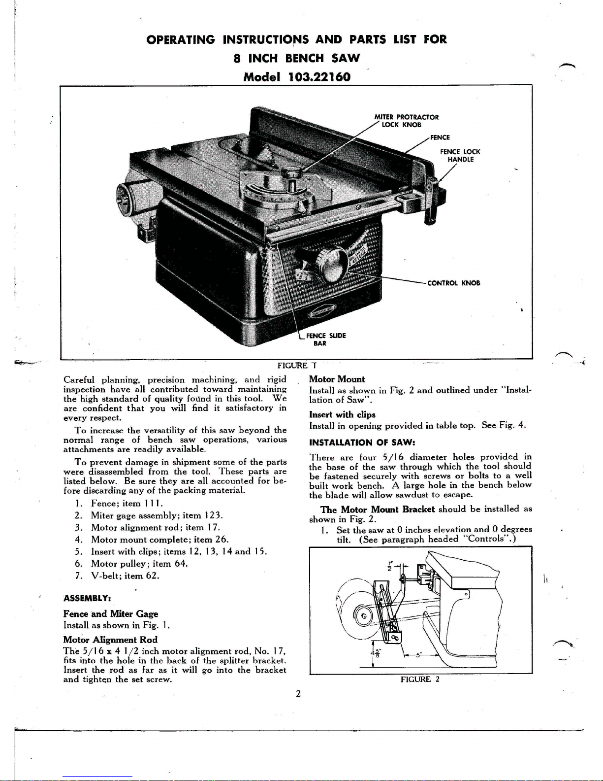
The Motor Mount Bracket should be installed as
shown in Fig. 2.
I. Set the saw at 0 inches elevation and 0 degrees
tilt. (See paragraph headed "Controls".)
FIGURE
-r
Careful planning, preCISIOn machining, and rigid Motor Mount
inspection have all contributed toward maintaining Install as shown in Fig. 2 and outlined under "Instal-
the high standard of quality found in this tool. We lation of Saw".
are confident that you will find it satisfactory in
every respect.
To increase the versatility of this saw beyond the
normal range of bench saw operations, various
attachments "are readily available.
To prevent damage in shipment some of the parts
were disassembled from the tool. These parts are
listed below. Be sure they are all accounted for be-
fore discarding any of the packing material.
I. Fence; item II I.
2. Miter gage assembly; item I23.
3. Motor alignment rod; item 17.
4. Motor mount complete; item 26.
5. Insert with clips; items 12, 13, 14 and 15.
6. Motor pulley; item 64.
7. V-belt; item 62.
ASSEMBLY:
Fence and Miter Gage
Install as shown in Fig. I.
Motor Alignment Rod
The 5/1 6 x 4 1/2 inch motor alignment rod, No. I7,
fits into the hole in the back of the splitter bracket.
Insert the rod as far as it will go into the bracket
and tighte:n the set screw.
2
r
 Loading...